
Statutory Rules 1995 No. 74
______________
Radiocommunications (Multipoint Distribution Station Licences - Regional Licences) Guidelines No. 1 of 1995
I, Christine Mary Goode, Spectrum Manager, make on behalf of the SMA the following Guidelines under section 112 of the Radiocommunications Act 1992.
Dated 3 April 1995
Christine M Goode
Spectrum Manager
PART 1 - PRELIMINARY
Citation
1. These Guidelines may be cited as the Radiocommunications (Multipoint Distribution Station Licences - Regional Licences) Guidelines No. 1 of 1995.
Commencement
2. These Guidelines come into force on 6 April 1995.
Interpretation
3. (1) In these Guidelines, unless the contrary intention appears:
“Act” means the Radiocommunications Act 1992;
“AHD” means Australian Height Datum;
“assessment area” in relation to an MDS transmitter in an area means the assessment area calculated in relation to that transmitter in accordance with Assessment A.3 or C of these Guidelines;
“area” has the same meaning as in the Determination;
“Coordination Handbook” means the Multipoint Distribution Station Coordination Handbook compiled by the SMA as in force on the date of commencement of these Guidelines;
“Coordination Regulations” means the Radiocommunications (Coordination) Regulations;
“Determination” means the Radiocommunications (Allocation of Multipoint Distribution Station Licences - Regional Licences) Determination No. 1 of 1995;
(i) determined by the SMA, under subsection 106 (1) of the Act on 4 April 1995; and
(ii) as in force on the date of commencement of these Guidelines;
‘EIRP’ means equivalent isotropically radiated power;
“fixed link” means a communications link between stations in the fixed (point-to-point) service;
“group” has the same meaning as in the Coordination Regulations;
“MDS channel” means a channel in a group;
“MDS licence” means an Multipoint Distribution Station Licence within the meaning of the Radiocommunications (Definitions) Determination No. 2 of 1993 as in force on 6 April 1995.
“MDS receiver” means a multipoint distribution receiver within the meaning of the Radiocommunications Regulations;
“MDS transmitter” means:
(i) a Multipoint Distribution Station within the meaning of the Radiocommunications Regulations; and
(ii) a Multipoint Distribution Station repeater within the meaning of the Radiocommunications Regulations; and
(iii) a station the operation of which is authorised by an MDS licence; and
(iv) a station which is the subject of a Transmitter proposal that is in effect under the Coordination Regulations;
“nominated applicant” has the same meaning as in the Coordination Regulations;
“primary fixed link” means a fixed link operating with primary status in a frequency band adjacent to an MDS band, including a fixed link with channel centre frequency that is adjacent to an MDS band but with emission overlapping that MDS band;
“RALI FX3” means the Radiocommunications Assignment and Licensing Instruction of that name compiled by the SMA as in force on the date of commencement of these Guidelines;
“Schedule” means a Schedule to these Guidelines;
“secondary fixed link” means a fixed link with secondary status operating in, or adjacent to an MDS channel;
“Spectrum Plan” means the Radiocommunications - Australian Spectrum Plan;
“transmitter proposal” has the same meaning as in the Coordination Regulations.
(2) For the purposes of these Guidelines:
(a) MDS channels are taken to be adjacent if their centre frequencies are separated by 7 MHz; and
(b) MDS transmitters are ‘co-sited’ with each other if they can be encompassed within a circle having a radius of 500 metres
(3) A reference in these Guidelines to an assessment is a reference to an assessment of that letter set out in Schedule 1.
[NOTE. In the assessments at Schedule 1 of these Guidelines, the calculation of certain values may be required. What is being calculated in each case is as follows:
(a) received power - the received power from an MDS transmitter at the output of an earth station receiver’s antenna into the receiver’s low noise amplifier; and
(b) received noise power - received noise power in the band 2290 - 2300 MHz from an MDS transmitter at the output of an earth station receiver’s antenna into that receiver’s low noise amplifier; and
(c) unwanted field strength - the field strength from any unwanted transmitter at a point on an MDS licence area or assessment area boundary; and
(d) unwanted power - the power from an MDS transmitter at the output of a fixed link receiver’s antenna; and
(e) wanted power - the power from a fixed link transmitter at the antenna output of a fixed link receiver in the same system.]
PART 2 - GUIDELINES
MDS Emissions
4. Subject to the Act and these Guidelines, where exercising its power:
(a) under section 107 of the Act to impose a condition on an MDS licence; or
(b) under section 111 of the Act to impose a further condition on, or to vary a condition of, an MDS licence;
the SMA must exercise the power for the purpose of ensuring that radiated power from an MDS transmit antenna to be operated under an MDS licence at angles of elevation of 5 degrees or more above the horizontal plane does not exceed the following EIRP limits:
(c) 100 Watts at 5 degrees, decreasing linearly to 31.6 Watts at 10 degrees; and
(d) 31.6 Watts between 10 degrees and 15 degrees; and
(e) 31.6 Watts at 15 degrees, decreasing linearly to 10 Watts at 20 degrees; and
(f) 10 Watts between 20 degrees and 90 degrees.
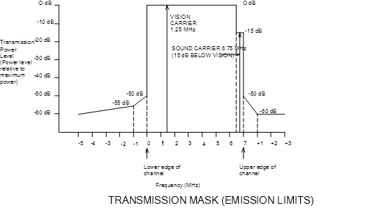
5. Subject to the Act, where exercising its power:
(a) under section 107 of the Act to impose a condition on an MDS licence; or
(b) under section 111 of the Act to impose a further condition on, or to vary a condition of, an MDS licence;
the SMA must exercise the power for the purpose of ensuring that the relative transmission power of an MDS transmitter to be operated under an MDS licence at any frequency does not exceed that shown in the following diagram.
ASSESSMENT A - MDS TRANSMITTER TO MDS RECEIVER
PURPOSE OF ASSESSMENT OF INTERFERENCE FROM MDS TRANSMITTER TO MDS RECEIVER
The assessments A.1, A.2 and A.3 below specify how to assess the potential for interference from an MDS transmitter to co-channel or adjacent channel MDS receivers for the purposes of Guidelines 14(a), (b) and (c).
A.1 MDS TRANSMITTER TO CO-CHANNEL MDS RECEIVERS IN OTHER LICENCE AREAS
A.1.1. This assessment (A.1) is intended to lead, where necessary, to the imposition of a licence condition aimed at ensuring that the field strength from an MDS transmitter does not exceed 32 dBuV/m in any other co‑channel licensee's MDS licence area.
Step 1: Identifying if an Interference Assessment is Necessary
A.1.2. The following information is needed to decide if an interference assessment must be carried out:
Information provided by MDS Licensee
- MDS transmitter location
- MDS transmitter channel
Information provided by the SMA
- MDS licence area boundaries
[NOTE. Details of the MDS licence area boundaries are contained in Schedule 1 to the Radiocommunications (Allocation of Multipoint Distribution Station Licences - Regional Licences) Determination No. 1 of 1995.]
A.1.3. An assessment of the potential for interference from an MDS transmitter to another MDS licence area is necessary if the MDS transmitter is to be located within a distance 'D' of another MDS licence area. The distance 'D' is determined from the height of the transmitting antenna of the MDS transmitter above average ground level and is indicated in the following table.
Height of Transmitting Antenna above Average Ground Level, Ht* (m) | D (km) |
Ht 37.5 | 65 |
37.5 Ht 75 | 75 |
75 Ht 150 | 90 |
150 Ht 300 | 110 |
300 Ht 600 | 135 |
600 Ht 1200 | 175 |
* Ht: the height of the MDS transmitting antenna above the average level of the ground between distances of 3 and 15 km from the transmitter in the direction of the nearest point on the boundary of another MDS licence area (see CCIR Rec 370-5).
[NOTE. Distances for MDS transmitters with heights of transmitting antennas greater than 1200 m above average ground level will be provided by the Customer Services Group of the SMA, if required.]
[NOTE. CCIR Recommendations are available from the Standards Australia International Sales Group, Strathfield NSW.]
A.1.4. If an interference assessment is necessary, the assessment will comprise the following Steps 2, 3 and 4.
Step 2: Calculating Terrain Loss
A.1.5. The following information is needed to complete this calculation:
Information provided by MDS licensee
- MDS transmitter location, site height and antenna height
- terrain profiles between the MDS transmitter and the point on the boundary of each other licence area identified at Step 1, that is nearest to the MDS transmitter
Information provided by the SMA
- MDS licence area boundaries
- nominal MDS receiver antenna height = 10m
[NOTE. Details of the MDS licence area boundaries are contained in Schedule 1 to the Radiocommunications (Allocation of Multipoint Distribution Station Licences - Regional Licences) Determination No. 1 of 1995.]
A.1.6. Using the method detailed at Schedule 2, calculate the terrain loss between the MDS transmitter and the point on the boundary of each other licence area identified at Step 1, that is nearest to the MDS transmitter.
[NOTE. If the protection criteria of Assessment A.1.10 are satisfied when a terrain loss value of Lt = 0 dB is used in the equation at Assessment A.1.8. then calculation of an actual value for Lt is not required.]
Step 3: Calculating Received Signal Levels
A.1.7. The following information is needed for this calculation:
Information provided by MDS licensee
- MDS transmitter power and antenna gain in the direction of the point on the boundary of each other licence area, identified at Step 1, that is nearest to the MDS transmitter
- terrain loss (as calculated at Step 2)
Information provided by the SMA
- none
A.1.8. The unwanted field strength is then calculated at the point on the boundary of each other MDS licence area identified at Step 1, that is nearest to the MDS transmitter. The following equation is used for this calculation:
Eu = 44.77 - 20log(d) + Pt + Gt – Lt
where:
Eu = unwanted field strength at the point (dBuV/m)
d = distance between the MDS transmitter and the point on the boundary of each other licence area identified at Step 1, that is nearest to the MDS transmitter (km)
Pt = MDS transmitter power (dBm)
Gt = gain of the MDS transmitter antenna in the direction of the point on the boundary of each other licence area identified at Step 1, that is nearest to the MDS transmitter (dBi)
Lt = terrain loss as calculated at Step 2 (dB)
Step 4: Assessing Received Signal Levels Against Protection Requirements
A.1.9. The following information is needed for this assessment:
Information provided by MDS licensee
- unwanted field strength (as calculated at Step 3)
Information provided by the SMA
- maximum permissible unwanted field strength in a co‑channel MDS licence area (see below).
A.1.10. An MDS transmitter will meet the protection requirements for co-channel MDS licence areas if:
Eu Em
where:
Eu = unwanted field strength at the point on the boundary of each other licence area identified at Step 1, that is nearest the MDS transmitter (as calculated at Step 3) (dBuV/m)
Em = 32 dBuV/m, the maximum permissible unwanted field strength in a co-channel MDS licence area
[NOTE. The results of Assessment A.1 may lead to the imposition or variation of licence conditions (see Guideline 14(a)).]
A.2 MDS TRANSMITTER TO ADJACENT CHANNEL MDS RECEIVERS IN OTHER LICENCE AREAS
A.2.1. This assessment (A.2) is intended to lead, where necessary, to the imposition of a licence condition aimed at ensuring that the field strength from an MDS transmitter does not exceed 76 dBuV/m in any other MDS licence area where transmitters are licensed to operate on adjacent MDS channels.
Step 1: Identifying if an Interference Assessment is Necessary
A.2.2. The following information is needed to decide if an interference assessment must be carried out:
Information provided by MDS Licensee
- MDS transmitter location
- MDS transmitter channel
Information provided by the SMA
- MDS licence area boundaries
[NOTE. Details of the MDS licence area boundaries are contained in Schedule 1 to the Radiocommunications (Allocation of Multipoint Distribution Station Licences - Regional Licences) Determination No. 1 of 1995.]
A.2.3. An assessment of the potential for interference from an MDS transmitter to another MDS licence area is necessary if the MDS transmitter is to be located within a distance 'D' of another licence area in which an MDS service is on an adjacent channel. The distance 'D' is determined from the EIRP of the MDS transmitter and is indicated in the following table:
EIRP* (dBm) | D (km) |
50 | 10 |
53 | 15 |
60 | 30 |
63 | 40 |
70 | 90 |
*EIRP: the EIRP of the MDS transmitter
Step 2: Calculating Terrain Loss
A.2.4. The following information is needed to complete this calculation:
Information provided by MDS licensee
- MDS transmitter location, site height and antenna height
- terrain profiles between the MDS transmitter and the point on the boundary of each other licence area identified at Step 1, that is nearest to the MDS transmitter
Information provided by the SMA
- MDS licence area boundaries
- nominal MDS receiver antenna height = 10m
[NOTE. Details of the MDS licence area boundaries are contained in Schedule 1 to the Radiocommunications (Allocation of Multipoint Distribution Station Licences - Regional Licences) Determination No. 1 of 1995.]
A.2.5. Using the method detailed at Schedule 2, calculate the terrain loss between the MDS transmitter and the point on the boundary of each other licence area identified at Step 1, that is nearest the MDS transmitter.
Step 3: Calculating Received Signal Levels
A.2.6. The following information is needed for this calculation:
Information provided by MDS licensee
- MDS transmitter power and antenna gain in the direction of the point on the boundary of each other licence area identified at Step 1, that is nearest to the MDS transmitter.
- terrain loss (as calculated at Step 2)
Information provided by the SMA
- none
A.2.7. The unwanted field strength is then calculated at the point on the boundary of each other MDS licence area identified at Step 1, that is nearest to the MDS transmitter. The following equation is used for this calculation:
Eu = 44.77 - 20log(d) + Pt + Gt – Lt
where:
Eu = unwanted field strength at the point(dBuV/m)
d = distance between the MDS transmitter and the point on the boundary of each other licence area identified at Step 1, that is nearest the MDS transmitter (km)
Pt = MDS transmitter power (dBm)
Gt = gain of the MDS transmitter antenna in the direction of the point on the boundary of each other licence area identified at Step 1, that is nearest to the MDS transmitter (dBi)
Lt = terrain loss (as calculated at Step 2) (dB)
Step 4: Assessing Received Signal Levels Against Protection Requirements
A.2.8. The following information is needed for this assessment:
Information provided by MDS licensee
- unwanted field strength (as calculated at Step 3)
Information provided by the SMA
- maximum permissible unwanted field strength in each other licence area in which licensees are on adjacent channels identified at Step 1 (see below)
A.2.9. An MDS transmitter will meet the protection requirements for adjacent channels in another licence area if:
Eu Em
where:
Eu = unwanted field strength at the point on the boundary of each other licence area identified at Step 1, that is nearest to the MDS transmitter (as calculated at Step 3) (dBuV/m)
Em = 76 dBuV/m, the maximum permissible unwanted field strength in other licence areas in which services are on adjacent channels
[NOTE. The results of Assessment A.2 may lead to the imposition or variation of licence conditions (see Guideline 14(b)).]
A.3 MDS TRANSMITTER TO ADJACENT CHANNEL MDS RECEIVERS IN THE SAME LICENCE AREA
A.3.1. This assessment (A.3) specifies how to assess the potential for interference from an MDS transmitter to a notional adjacent channel MDS receiver lying within a defined area (called an assessment area) around an adjacent channel MDS transmitter operating in the same licence area.
A.3.2 The assessment is intended to lead to the imposition, where necessary, of a licence condition aimed at ensuring that the field strength from an MDS transmitter will not exceed 76 dBuV/m in the assessment area around any adjacent channel transmitter operating in the same licence area.
Step 1: Identifying if an Interference Assessment is Necessary
A.3.3. The following information is needed to identify if an interference assessment must be carried out:
Information provided by MDS Licensee
- MDS transmitter location
- MDS transmitter channel
[NOTE. The location and channel of the MDS transmitter are required because the notional MDS receiver for which this assessment (A.3.) may be required is deemed to be lying within the assessment area around that MDS transmitter. The assessment area is bounded by a circle of radius R kilometres from the MDS transmitter. The radius R is derived from the transmitter height and EIRP, and is calculated in accordance with Schedule 3. See also A.3.9. below.]
Information provided by the SMA
- location of existing adjacent channel MDS transmitters within the same licence area
[NOTE. Information on the location of licensed MDS transmitters is held by the Spectrum Management Agency.]
A.3.4. It is not necessary to carry out the adjacent channel interference assessment in this section in relation to a transmitter and another MDS transmitter in the same licence area, if the MDS transmitters are ‘co-sited’.
[NOTE. Transmitters are taken to be co-sited with each other if they can be encompassed within a circle having a radius of 500 metres (see Guideline 3(2).]
A.3.5. An assessment of the potential for interference must be carried out if:
(a) the MDS transmitters are not co-sited (see Guideline 3(2)); and
(b) an MDS transmitter is to be located within a distance 'D' of an adjacent channel MDS transmitter operating in the same MDS licence area.
A.3.6. The distance 'D' referred to in A.3.5.(b) above is determined from the EIRP of the MDS transmitter and is indicated in the table below.
EIRP* (dBm) | D (km) |
50 | 155 |
53 | 160 |
60 | 175 |
63 | 185 |
70 | 235 |
* EIRP: the EIRP of the MDS transmitter
Step 2: Calculating Terrain Loss
A.3.7.The following information is needed to complete this calculation:
Information provided by MDS licensee
- MDS transmitter location, site height and antenna height
- terrain profiles between the MDS transmitter and the point nearest the MDS transmitter, in each assessment area around adjacent channel MDS transmitters identified at Step 1.
[NOTE. For the purpose of this assessment, the point described above represents the location of the antenna of a notional MDS receiver, with nominal antenna height as specified below.]
Information provided by the SMA
- MDS licence area boundaries
- nominal MDS receiver antenna height = 10m
- location of existing adjacent channel MDS transmitters within the same licence area
[NOTE. Details of the MDS licence area boundaries are contained in Schedule 1 to the Radiocommunications (Allocation of Multipoint Distribution Station Licences - Regional Licences) Determination No. 1 of 1995. Details of the location of existing adjacent channel MDS transmitters are held by the SMA.]
A.3.8. The assessment area for an MDS transmitter is the area bounded by a circle of radius R kilometres from each of the adjacent channel MDS transmitters identified at Step 1. R is calculated using Schedule 3.
A.3.9. Using the method detailed at Schedule 2, calculate the terrain loss between the MDS transmitter and the nearest point on the boundary of the assessment area for each adjacent channel transmitter identified at Step 1.
[NOTE. If the protection criteria of Assessment A.3.13. are satisfied when a terrain loss value of Lt = 0 dB is used in the equation at Assessment A.3.11 then calculation of an actual value for Lt is not required.]
Step 3: Calculating Received Signal Levels
A.3.10. The following information is needed for this calculation:
Information provided by MDS licensee
- MDS transmitter power and antenna gain in the direction of the nearest point on the boundary of the assessment area for each adjacent channel transmitter.
- terrain loss (as calculated at Step 2)
Information provided by the SMA
- none
A.3.11. The unwanted field strength is then calculated at the nearest point on the boundary of the assessment area for each adjacent channel transmitter. The following equation is used for this calculation:
Eu = 44.77 - 20log(d) + Pt + Gt – Lt
where:
Eu = unwanted field strength at a point in the assessment area around an adjacent channel transmitter (dBuV/m)
d = distance between the MDS transmitter and the nearest point on the boundary of the assessment area around an adjacent channel transmitter (km)
Pt = MDS transmitter power (dBm)
Gt = gain of the MDS transmitter antenna in the direction of the nearest point on the boundary of the assessment area for an adjacent channel transmitter (dBi)
Lt = terrain loss (as calculated at Step 2) (dB)
Step 4: Assessing Received Signal Levels Against Protection Requirements
A.3.12. The following information is needed for this assessment:
Information provided by MDS licensee
- unwanted field strength (as calculated at Step 3)
Information provided by the SMA
- maximum permissible unwanted field strength in the assessment area for each adjacent channel transmitter in the same licence area (see below)
A.3.13. An MDS transmitter will meet the protection requirements for adjacent channels in the same MDS licence area if:
Eu Em in the assessment area around each adjacent channel transmitter in the same licence area (identified at Step 2)
where:
Eu = unwanted field strength at the nearest point on the boundary of the assessment area for each adjacent channel transmitter (as calculated at Step 3) (dBuV/m)
Em = 76 dBuV/m, the maximum permissible unwanted field strength in the assessment area around an adjacent channel transmitter in the same licence area
[NOTE. The results of Assessment A.3 may lead to the imposition or variation of licence conditions (see Guideline 14(c)).]
ASSESSMENT B MDS TRANSMITTER TO FIXED LINK RECEIVER
PURPOSE OF ASSESSMENT OF INTERFERENCE FROM MDS TRANSMITTER TO FIXED LINK RECEIVER
This Assessment B specifies how to assess the potential for interference from a proposed MDS transmitter to a primary or secondary fixed link receiver for the purposes of Guideline 14(d).
[NOTE. The references in steps 1 to 4 below to 'fixed link' receivers are to both primary and secondary fixed link receivers.]
The assessment is intended to lead, where necessary, to the imposition of a licence condition aimed at ensuring that the unwanted power from an MDS transmitter does not exceed a particular value at any primary fixed link receiver operating in a particular frequency band.
Step 1: Identifying if an Interference Assessment is Necessary
B.1. The following information is needed to decide if an interference assessment must be carried out:
Information provided by MDS Licensee
- MDS transmitter location
- MDS transmitter frequency
Information provided by the SMA
- location and frequency of fixed links
[NOTE. Details of the location of existing fixed links are held by the SMA.]
B.2. An assessment of the potential for interference from a proposed MDS transmitter to a fixed link receiver is necessary if the proposed MDS transmitter is located within 200 km of the fixed link receiver and the receiver is licensed to operate in the frequency range:
2030 - 2157 MHz for Group A MDS channels; or
2256 - 2420 MHz for Group B MDS channels.
B.3. If an assessment is necessary, the assessment will comprise the following steps 2 to 4.
Step 2: Calculating Propagation Loss
B.4. The following information is needed to complete this calculation:
Information provided by MDS licensee
- proposed MDS transmitter location, site height and antenna height
- fixed link transmitter and receiver site heights (found by knowing fixed link location)
- terrain profile between the proposed MDS transmitter and fixed link receiver of the fixed link under assessment
- terrain profile between the fixed link transmitter and fixed link receiver of the fixed link under assessment
Information provided by the SMA
- fixed link transmitter location and antenna height
- fixed link receiver location and antenna height
B.5. Using the method detailed at Schedule 2, propagation loss between antennas is to be calculated for:
(a) the fixed link receiver under assessment and the associated fixed link transmitter; and
(b) the proposed MDS transmitter and the fixed link receiver under assessment.
Step 3: Calculating Received Signal Levels
B.6.1. Calculating Wanted Power (at the fixed link receiver)
B.6.1.1. The following information is needed for this calculation:
Information provided by MDS licensee
- propagation loss between antennas calculated for the fixed link receiver under assessment and the associated fixed link transmitter (see Step 2, para. B.5.(a))
Information provided by the SMA
- fixed link transmitter power and antenna gain
- fixed link receiver antenna gain
B.6.1.2. The wanted power (at the fixed link receiver) is then calculated using the following equation:
Pw = Pt + Gt – Lb + Gr
where:
Pw = wanted power (dBm)
Pt = fixed link transmitter power (dBm)
Gt = gain of the fixed link transmitter antenna in the direction of the fixed link receiver (dBi)
Lb = propagation loss (as calculated at Step 2) (dB)
Gr = gain of the fixed link receiver antenna in the direction of the fixed link transmitter (dBi)
[NOTE. If either the transmitter power or the antenna gain of the link under consideration is not held by the Spectrum Management Agency, the value of the EIRP held by the Spectrum Management Agency in respect of the link may be used in lieu of the combined value of Pt + Gt. If no value of the EIRP in respect of the link is held by the Spectrum Management Agency, then the values of Pt and Gt must be sought from the fixed link licensee.]
B.6.2 Calculating Unwanted Power (at the fixed link receiver)
B.6.2.1. The following information is needed for this calculation:
Information provided by MDS licensee
- propagation loss between antennas for the proposed MDS transmitter and the fixed link receiver under assessment (see Step 2. para B.5.(b))
- proposed MDS transmitter power and antenna radiation pattern
Information provided by the SMA
- fixed link receiver antenna radiation pattern
B.6.2.2. The unwanted power (at the fixed link receiver) is then calculated using the following equation:
Pu = Pt + Gtf – Lb + Grm
where:
Pu = unwanted power(dBm)
Pt = proposed MDS transmitter power (dBm)
Gtf = gain of the proposed MDS transmitter antenna in the direction of the fixed link receiver (dBi)
Lb = propogation loss between antennas for the proposed MDS transmitter and the fixed link receiver under assessment (see Step 2, para. B.5.(b))(dB)
Grm = gain of the fixed link receiver antenna in the direction of the proposed MDS transmitter (dBi)
[NOTE. Details of the boresight gain are generally held by the SMA. This gain value should then be de-rated in accordance with the 2.1 GHz Fixed Link Notional Antenna Radiation Pattern at Schedule 4, to find the off-axis gain (Grm) in the relevant direction. If the boresight gain for the fixed link receive antenna is not held by the Spectrum Management Agency, the value must be sought from the fixed link licensee.]
Step 4: Assessing Receive Levels Against Protection Requirements
B.7. The following information is needed for this assessment:
Information provided by MDS licensee
- wanted and unwanted power (as calculated at Step 3)
- MDS transmitter channel centre frequency
Information provided by the SMA
- fixed link receiver protection requirements (see Schedule 5)
- fixed link receiver centre frequency (fr)
[NOTE. The details of the centre frequency of fixed link receivers are held by the Spectrum Management Agency.]
B.8. A proposed MDS transmitter will meet the protection requirements for fixed link receivers if:
Pw - Pu ≥ PR
where:
Pw = wanted power, calculated at step 3 (dBm)
Pu = unwanted power, calculated at step 3 (dBm)
PR = is the protection ratio required by a fixed link receiver from an MDS transmitter at frequency offset of fo MHz (dB) (see Schedule 5)
fo = frequency difference between MDS transmitter frequency and fixed link receiver frequency (MHz)
fo is calculated from the equation:
fo = the absolute value of (fMDS - fr)
where:
fMDS = MDS transmitter channel centre frequency (MHz)
fr = fixed link receiver centre frequency (MHz)
[NOTE. The results of Assessment D may lead to the imposition of licence conditions, see Guideline 14(e)).]
[NOTE. Secondary fixed link receivers cannot claim protection from interference from an MDS transmitter. The SMA will advise the licensee of the secondary fixed link of the potential for interference. Secondary fixed link licences should already be subject to the condition that the service cannot claim protection from, or cause interference to, services of a primary status. If not, a licence condition may be imposed on the licence authorising operation of the secondary fixed link (see Guideline 15).]
ASSESSMENT C - FIXED LINK TRANSMITTER TO MDS RECEIVER
PURPOSE OF ASSESSMENT OF INTERFERENCE FROM FIXED LINK TRANSMITTER TO MDS RECEIVER
This Assessment C specifies how to assess the potential for interference from a primary or secondary fixed link transmitter to a notional MDS receiver lying within a defined area (called an assessment area).
This assessment is intended to lead, where necessary, to the imposition of a licence condition on a secondary fixed link transmitter, where the unwanted field strength from that secondary fixed link transmitter received by a notional MDS receiver in an assessment area is calculated to exceed protection requirements (see C.9. below).
[NOTE. The references in steps 1 - 4 below to 'fixed link' transmitters are to both primary and secondary fixed link transmitters.]
Step 1: Identifying if an Interference Assessment is Necessary
C.1. The following information is needed to decide if an interference assessment must be carried out:
Information provided by MDS Licensee
- MDS transmitter location
- MDS transmitter frequency
[NOTE. The location and channel of the MDS transmitter are required because the notional MDS receiver for which this assessment (C) may be required is deemed to be lying within the assessment area around that MDS transmitter. The assessment area is bounded by a circle of radius R kilometres from the MDS transmitter. The radius R is related to the transmitter height and EIRP, and is calculated in accordance with Schedule 3. See also C.4. below.]
Information provided by the SMA
- location and frequency of fixed links
[NOTE. The details of the location and frequency of fixed link receivers are held by the Spectrum Management Agency.]
C.2. An assessment of the potential for interference to an MDS receiver from a fixed link transmitter is necessary if the MDS transmitter is located within a distance D from a fixed link transmitter as indicated in the following table, and the fixed link transmitter is operating in the frequency range:
2040 - 2147 MHz for Group A MDS channels; or
2266 - 2420 MHz for Group B MDS channels.
Ht* (metres) | | EIRP** | (Watts) | | |
| 100 | 200 | 1000 | 2000 | 10000 |
37.5 | 216 | 222 | 227 | 229 | 234 |
75 | 216 | 223 | 237 | 239 | 244 |
150 | 216 | 223 | 250 | 252 | 257 |
300 | 216 | 223 | 250 | 271 | 277 |
600 | 216 | 223 | 250 | 271 | 304 |
1200 | 216 | 223 | 250 | 271 | 344 |
Values for D (km)
* Ht: MDS transmitting antenna height above the average level of the ground between distances of 3 and 15 km from the transmitter in the direction of the receiver (see CCIR Rec 370-5)
**EIRP: the EIRP of the proposed MDS transmitter
[NOTE. CCIR Recommendations are available from the Standards Australia International Sales Group, Strathfield NSW.]
Step 2: Calculating Terrain Loss
C.3. The following information is needed to complete this calculation:
Information provided by MDS Licensee
- location and site height of the point in the assessment area around the proposed MDS transmitter nearest to the fixed link transmitter
[NOTE. For the purpose of this assessment, the point described above represents the location of the antenna of a notional MDS receiver, with nominal antenna height as specified below.]
- fixed link transmitter site height (determined by knowing the fixed link transmitter location)
- terrain profile between the fixed link transmitter and the point in the assessment area around the MDS transmitter nearest to the fixed link transmitter
Information provided by the SMA
- fixed link transmitter location and antenna height
- nominal MDS receiver antenna height = 10m
[NOTE. The details of the locations and of some antenna heights of fixed link transmitters are held by the Spectrum Management Agency. If the antenna height of the link under consideration is not held by the Spectrum Management Agency a height of 70 m may be used, or specific height information sought from the fixed link licensee.]
C.4. The assessment area is bounded by a circle of radius R kilometres from an MDS transmitter. The radius R is proportional to the transmitter height and EIRP, and is calculated in accordance with Schedule 3.
C.5. Using the method detailed at Schedule 2, calculate the terrain loss between the fixed link transmitter and the point in the assessment area around the MDS transmitter that is nearest to the fixed link transmitter.
[NOTE. If the protection criteria of Assessment C.9. are satisfied when a terrain loss value of Lt = 0 dB is used in the equation at assessment C.7. then calculation of an actual value for Lt is not required.]
Step 3: Calculating Received Signal Levels
C.6. The following information is needed for this calculation:
Information provided by MDS Licensee
- terrain loss (calculated in the same manner as under Step 2, para C.5)
Information provided by the SMA
- fixed link transmitter power and antenna gain in the direction of the point in the assessment area around the MDS transmitter that is nearest to the fixed link transmitter
C.7. The unwanted field strength (at an MDS receiver) is then calculated at the point in the assessment area around the MDS transmitter that is nearest to the fixed link transmitter using the following equation:
Eu = 44.77 - 20log(d) + Pt + Gtm – Lt
where:
Eu = unwanted field strength (dBuV/m)
d = distance between fixed link transmitter and the point in the assessment area around the MDS transmitter that is nearest to the fixed link transmitter (km)
Pt = fixed link transmitter power (dBm)
Gtm = gain of the fixed link transmitter antenna in the direction of the point in the assessment area around the MDS transmitter that is nearest to the fixed link transmitter (dBi)
Lt = terrain loss (as calculated at Step 2)(dB)
[NOTE. The Spectrum Management Agency holds details of both the power, and the antenna gain, of fixed link transmitters. If either the transmitter power or the antenna gain of the link under consideration is not held by the Spectrum Management Agency, the value in the EIRP data field may be used in lieu of the combined value of Pt + Gt. If the EIRP is also not held by the Spectrum Management Agency, then the values of Pt and Gt must be sought from the fixed link licensee. The boresight gain value (or EIRP, as applicable) should then be de-rated in accordance with the 2.1 GHz Fixed Link Notional Antenna Radiation Pattern at Schedule 4, to find the off-axis gain (Gtm) (or EIRP) in the relevant direction. Note that off-axis antenna gain (or EIRP) should be considered in both the horizontal and vertical planes.]
Step 4: Assessing Received Signal Levels Against Protection Requirements
C.8. The following information is needed for this assessment:
Information provided by MDS Licensee
- unwanted field strength (as calculated at Step 3)
- MDS transmitter channel centre frequency
Information provided by the SMA
- MDS receiver protection requirements (see Schedule 6)
- fixed link transmitter centre frequency (ft)
C.9. A fixed link transmitter will meet the protection requirements for MDS receivers if:
Eu Em
where:
Eu = unwanted field strength calculated at Step 3 (dBuV/m)
Em = the maximum permissible unwanted field strength in the assessment area around the MDS transmitter at frequency offset of fo MHz (dBuV/m) (see Schedule 6)
fo = frequency difference between MDS transmitter channel centre frequency and fixed link transmitter frequency (MHz)
fo is calculated from the equation:
fo = the absolute value of (fMDS - ft)
where:
fMDS = MDS transmitter channel centre frequency (MHz)
ft = fixed link transmitter centre frequency (MHz)
[NOTE. Details of the centre frequencies of fixed link transmitters are held by the SMA.]
[NOTE. The results of Assessment C may lead to the imposition of licence conditions, see Guideline 16.]
ASSESSMENT D - MDS TRANSMITTER TO EARTH STATION RECEIVER
This Assessment D specifies how to assess the potential for interference from an MDS Group B transmitter to an earth station receiver in the space research service.
A detailed discussion of the interference mechanisms between MDS and earth stations can be found in Section 2 Part B of the Coordination Handbook.
The SMA considers that earth station receivers in the space research service are not likely to receive interference from Group A MDS transmitters. Accordingly, no assessment of the interference potential to earth station receivers from Group A MDS transmitters need be carried out.
Step 1: Identifying if an Interference Assessment is Necessary
D.1. The following information is needed to decide if an interference assessment must be carried out:
Information provided by MDS Licensee
- MDS transmitter location
- MDS transmitter EIRP (in dBm)
Information provided by the SMA
- Location of Parkes earth station
- Location of Tidbinbilla earth station
[NOTE. For information on the locations of the Parkes and Tidbinbilla earth stations see Schedule 7.]
Parkes
D.2. An assessment of the potential for interference to the Parkes earth station is necessary if an MDS transmitter is to be located within a circle around the Parkes facility of radius:
250 km | for an MDS transmitter EIRP 60 dBm |
250 + 12(EIRP - 60) km | for an MDS transmitter EIRP 60 dBm |
Tidbinbilla
D.3. An assessment of the potential for interference to the Tidbinbilla earth station is necessary if an MDS transmitter is to be located within a circle around the Tidbinbilla facility of radius:
180 km | for an MDS transmitter EIRP 60 dBm |
180 + 12(EIRP - 60) km | for an MDS transmitter EIRP 60 dBm |
D.4 If an interference assessment is necessary, the assessment will comprise the following steps 2 - 4.
Step 2: Calculating Propagation Loss
D.5. The following information is needed to complete this calculation:
Information provided by MDS Licensee
- MDS transmitter location, site height, antenna height and antenna gain in the direction of the earth station receiver
- terrain profile between MDS transmitter and earth station receiver
Information provided by the SMA
- Earth station receiver location, site height, antenna height and antenna gain in the direction of the MDS transmitter (see Schedule 7)
- required time percentage for which the calculated basic transmission loss is not exceeded (see Schedule 8)
- meteorological data for path profile under assessment (see Schedule 8)
D.6. The propagation loss between the MDS transmitter and the earth station receiver under assessment is to be calculated using ITU Rec 452-5 (see Schedule 8).
[NOTE. ITU Recommendations are available from the Standards Australia International Sales Group, Strathfield NSW.]
Step 3: Calculating Received Signal Levels
D.7. Calculating Received Power (at the earth station receiver)
D.7.1. The following information is needed for this calculation:
Information provided by MDS Licensee
- MDS transmitter power
- MDS antenna gain in the direction of the earth station receiver
- propagation loss (as calculated at Step 2)
Information provided by the SMA
- earth station receiver antenna gain
- allowance factor for multiple MDS transmitters
D.7.2. The received power (at the earth station receiver) is then calculated using the following equation:
Pr = Pt + Gte – Lb + Grm + Fa
where:
Pr = power received (dBm)
Pt = proposed MDS transmitter power (dBm)
Gte = proposed MDS antenna gain in the direction of the earth station receiver (dBi)
Lb = propagation loss (as calculated at Step 2) (dB)
Grm = gain of the earth station antenna in the direction of the MDS transmitter (dBi) (see Schedule 7)
Fa = factor to account for the additive contributions from multiple MDS transmissions (dB) (see Schedule 7)
D.8. Calculating Received Noise Power (at the earth station receiver)
D.8.1. The following information is needed for this calculation:
Information provided by MDS licensee
- MDS transmitter power
- MDS antenna gain in the direction of the earth station receiver
- propagation loss (as calculated at Step 2)
Information provided by the SMA
- earth station receiver antenna gain
- MDS emission limits in the band 2290 - 2300 MHz
- allowance factor for multiple MDS transmitters
D.8.2. The received noise power (at the earth station receiver) is then calculated using the following equation:
Prn = Ptn – Lb + Grm + Fa
where:
Prn = received noise power (dBm in a 1 Hz bandwidth)
Ptn = deemed transmitted MDS noise power in the band 2290 ‑ 2300 MHz* (dBm in a 1 Hz bandwidth)
Lb = propagation loss (as calculated at Step 2) (dB)
Grm = gain of the earth station antenna in the direction of the MDS transmitter (dBi) (see Schedule 7)
Fa = factor to account for the additive contributions from multiple MDS transmissions (dB) (see Schedule 7)
* For the purposes of this calculation, the transmitted MDS noise power (Ptn) is deemed to be:
for channel 6 transmitters | (EIRP - 56.25) dBm in a 1 Hz bandwidth |
for channel 7 - 19 transmitters | (EIRP - 90) dBm in a 1 Hz bandwidth |
where:
EIRP is the equivalent isotropically radiated power (in dBm) of the proposed MDS transmitter in the direction of the earth station receiver
[NOTE. If a licensee can demonstrate to the SMA that the noise power of the proposed MDS transmitter is less than the relevant limit specified above, then the actual noise power of the proposed transmitter may be used instead of the deemed noise power.]
[NOTE. The rationale for this approach is given in the Coordination Handbook.]
Step 4: Assessing Receive Levels Against Protection Requirements
D.9. An MDS transmitter will meet the earth station receiver protection requirements if the levels calculated at Step 3 do not exceed those listed below:
Parkes
receiver overload Prmax = -30 dBm in the band 2240 - 2340 MHz
noise floor degradation Prnmax = -192 dBm in a 1 Hz bandwidth in the
band 2290 - 2300 MHz
Tidbinbilla
receiver overload Prmax = -84 + 3.5(n-6) dBm
(n is the MDS channel number in the range 6 to 19)
noise floor degradation Prnmax = -192 dBm in a 1 Hz bandwidth in the
band 2290 - 2300 MHz
[NOTE. The results of Assessment D may lead to the imposition of licence conditions, see Guideline 14.]
Propagation Loss Components
In calculating the propagation loss between MDS services, and between MDS services and fixed links, the basic propagation loss (Lb) between two antennas may be represented by the following components:
• a free space basic transmission loss (Lbf); and
an additional component due to the presence of terrain (Lt)
ie Lb = Lbf + Lt
Initial assessments may be made using the free space transmission loss component only (ie Lt = 0). If, as a result of this assessment, the specified protection requirements are met then the more complex assessment that includes terrain loss is not required.
For the purpose of paragraph B.5 (a) of Step 2 in Assessment B, the propagation loss between fixed link transmitters and fixed link receivers should be calculated using only the free space basic transmission loss (Lbf).
Free Space Loss
The free space loss component (Lbf) is calculated by the following formula:
Lbf = 32.44 + 20log(f) + 20 log(d)
where:
f = frequency (MHz)
d = distance (km)
Terrain Loss
The terrain loss (Lt) may be calculated by using Method A or Method B below. Alternatively, where there is more than one obstacle, ITU Recommendation 526‑2 'Propagation by Diffraction' may be used for calculation of terrain loss.
[NOTE. ITU Recommendations are available from the Standards Australia International Sales Group, Strathfield NSW.]
Method A: Diffraction over a spherical Earth
Terrain loss due to diffraction over a spherical Earth is calculated using the formulas below. These formulas are valid for systems operating above 1 GHz and apply to both horizontal and vertical polarisation.
Lt = -(F(X) + G(Y1) + G(Y2)) (dB)
where:
Lt = terrain loss due to diffraction over a smooth sphere (dB)
X = the normalised length of the path between the antennas at normalised heights Y1 and Y2
X = 2.2f1/3ae-2/3d
Yn = 0.0096f2/3ae-1/3Hn
ae = kr [ie, the equivalent Earth's radius (km); see ITU-Rec. 310-8]
r = 6370 km (earth radius)
k = equivalent earth radius factor (nominally 4/3)
Hn = antenna height above the spherical Earth (m)
d = path length (km)
f = frequency (MHz)
[NOTE. ITU Recommendations are available from the Standards Australia International Sales Group, Strathfield NSW.]
The distance term is given by :
F(X) = 11 + 10log(X) - 17.6X
The height gain term is given by :
G(Yn) = 17.6(Yn - 1.1)1/2 - 5log(Yn - 1.1) - 8 for Yn > 2
G(Yn) = 20log(Yn + 0.1Yn3) for Yn < 2
If the equation for Lt gives a value less than zero, the method is invalid, and Lt is to be taken as zero.
Method B: Single knife edge diffraction loss calculation
Terrain loss due to diffraction over a single knife edge obstacle is calculated using the formulas below.
Lt = 6.9 + 20log {[(v -0.1)2 + 1]_ + v - 0.1} for v > -0.7
where:
Lt = terrain loss due to knife edge diffraction (dB)
v = Ho(fd/150d1d2)_
Ho = height (m) of the top of the obstacle above the straight line joining the two ends of the path
d1, d2 = distances (km) of the two ends of the path from the top of the obstruction
d = path length (km),
f = frequency (GHz)
[NOTE: For situations where v -0.7 see CCIR Recommendation 526-2. CCIR Recommendations are available from the Standards Australia International Sales Group, Strathfield NSW.]
For EIRP 63 dBm
R = 
For EIRP 63 dBm and Ht 300 m
R = 71 + (EIRP-63)/1.2271
For EIRP 63 dBm and Ht 300 m
R =  for EIRP 26.03 - 20log(x)
or,
R = x + (EIRP-Pi)/1.2271 for EIRP Pi
Pi = 26.03 - 20log(x)
where:
EIRP : EIRP of the adjacent channel transmitter (dBm)
Ht : height of the transmitting antenna over the average level of the ground between distances of 3 and 15 km from the transmitter in the direction of the receiver (m)
x : distance to the horizon (km)
where:
x = x' + 8.1493log(x'/71)
x' = G/1.2271 + 71
G = 17.6y0.5 - 5log(y) - 78.446
y = 24.589Ht/300 - 1.1
The table below provides values for R based on specific values of Ht and EIRP. It can be used to verify values of R calculated in accordance with the above method.
Ht* (metres) | | | EIRP** (Watts) | | |
| 100 | 200 | 1000 | 2000 | 10000 |
37.5 | 16 | 22 | 27 | 29 | 34 |
75 | 16 | 23 | 37 | 39 | 44 |
150 | 16 | 23 | 50 | 52 | 57 |
300 | 16 | 23 | 50 | 71 | 77 |
600 | 16 | 23 | 50 | 71 | 104 |
1200 | 16 | 23 | 50 | 71 | 144 |
Values for R (km)
* Ht: MDS transmitting antenna height above the average level of the ground between distances of 3 and 15 km from the transmitter in the direction of the receiver (see CCIR Rec 370-5)
**EIRP: the EIRP of the proposed MDS transmitter
[NOTE. CCIR Recommendations are available from the Standards Australia International Sales Group, Strathfield NSW.]
Frequency | PROTECTION RATIO (dB) | |
Offset, fo
(MHz) | Digital
Emission
8 MHz | Digital
Emission
15 MHz | Digital
Emission
28 MHz | FM Video
Emission
28 MHz |
0 fo 12.5 | 60 | 60 | 60 | 60 |
12.5 fo 13.0 | 6 | 49 | 52 | 52 |
13.0 fo 19.5 | 4 | 43 | 51 | 51 |
19.5 fo 20.0 | -28 | 29 | 25 | 25 |
20.0 fo 25.5 | N/A | 29 | 25 | 25 |
25.5 fo 26.5 | N/A | 26 | 25 | 25 |
26.5 fo 27.0 | N/A | 25 | 25 | 25 |
27.0 fo 27.5 | N/A | 23 | 25 | 25 |
27.5 fo 32.5 | N/A | 23 | 25 | 25 |
32.5 fo 33.5 | N/A | -27 | 21 | 21 |
33.5 fo 34.0 | N/A | N/A | 20 | 20 |
34.0 fo 34.5 | N/A | N/A | 18 | 18 |
34.5 fo 39.5 | N/A | N/A | 18 | 18 |
39.5 fo 40.0 | N/A | N/A | 13 | 13 |
40.0 fo 40.5 | N/A | N/A | 9 | 9 |
40.5 fo 41.0 | N/A | N/A | 9 | 9 |
41.0 fo 41.5 | N/A | N/A | 9 | 9 |
41.5 fo 42.0 | N/A | N/A | 9 | 9 |
42.0 fo 46.5 | N/A | N/A | 6 | 6 |
46.5 fo 47.0 | N/A | N/A | 2 | 2 |
47.0 fo 48.0 | N/A | N/A | 2 | 2 |
48.0 fo 48.5 | N/A | N/A | -1 | -1 |
48.5 fo 49.0 | N/A | N/A | -1 | -1 |
fo 49.0 | N/A | N/A | N/A | N/A |
| | | | | |
The above protection ratios are based on the concepts contained in RALI FX 3. The digital protection ratios are for a 60 km path length and PL = 20. For other path lengths and PL values the appropriate path length correction factor must be added (refer to the graph and seasonal contour maps below (see pages 45 and 46 respectively). The contour map which yields the highest value of PL must be used. Note that the entry N/A means that fixed links at the indicated frequency offsets do not need to be considered.
[NOTE. PL - percentage of time that the average refractivity gradient in the lowest 100 m of the atmosphere is less than -100 N units/km.]
[NOTE. The seasonal contour maps may be obtained from RALI FX3.]
Frequency | Maximum Permissible Unwanted Field Strength (dBuV/m) |
Offset, fo
(MHz) | Digital
Emission
8 MHz | Digital
Emission
15 MHz | Digital
Emission
28 MHz | FM Video
Emission
28 MHz |
0 fo 12.5 | 32 | 32 | 32 | 32 |
12.5 fo 13.0 | 72 | 65 | 41 | 59 |
13.0 fo 19.5 | 75 | 69 | 43 | 62 |
19.5 fo 20.0 | 120 | 93 | 73 | 86 |
20.0 fo 25.5 | 122 | 100 | 75 | 88 |
25.5 fo 26.5 | N/A | 113 | 86 | 101 |
26.5 fo 27.0 | N/A | 116 | 87 | 102 |
27.0 fo 27.5 | N/A | 118 | 88 | 103 |
27.5 fo 32.5 | N/A | 120 | 89 | 105 |
32.5 fo 33.5 | N/A | N/A | 99 | 147 |
33.5 fo 34.0 | N/A | N/A | 103 | N/A |
34.0 fo 34.5 | N/A | N/A | 105 | N/A |
34.5 fo 39.5 | N/A | N/A | 107 | N/A |
39.5 fo 40.0 | N/A | N/A | 148 | N/A |
fo 40.0 | N/A | N/A | N/A | N/A |
[NOTE. The entry N/A means that fixed links at the indicated frequency offsets do not need to be considered.]
Gnangara Earth Station
Australian Map Grid coordinates for the Gnangara facility are:
Zone 50
Easting 394330
Northing 6480766
Site height 40 m AHD
Antenna height 50 m
Antenna gain in the direction of MDS receiver (Gtm) 20 dBi
Earth station transmitter power 2 kW
Parkes Earth Station
Australian Map Grid coordinates for the Parkes facility are:
Zone 55
Easting 618000
Northing 6348000
Site height 360 m AHD
Antenna height 50 m
Antenna gain in direction of MDS transmitter (Grm) 0 dBi
Allowance for multiple MDS transmitters (Fa)
received power 8 dB
noise power 0 dB (channel 6)
11 dB (channels 7 - 19)
Tidbinbilla Earth Station
Australian Map Grid coordinates for the Tidbinbilla facility are:
Zone 55
Easting 679700
Northing 6080400
Site height 640 m AHD
Antenna height 50 m
Antenna gain in direction of MDS transmitter (Grm) 53 dBi
Antenna gain in direction of MDS receiver (Gtm) 53 dBi
Earth station transmitter power 20 kW
Allowance for multiple MDS transmitters (Fa)
received power 3 dB
noise power 0 dB (channel 6)
11 dB (channels 7 - 19)
Basic Transmission Loss Calculation
International Telecommunication Union (ITU) Recommendation 452-5: "Prediction Procedure for the Evaluation of Microwave Interference Between Stations on the Surface of the Earth at Frequencies Above About 0.7 GHz" (1992) is specifically intended for interference prediction purposes, and is to be used for the calculation of basic transmission loss (ie propagation loss) between MDS services and earth stations in the space research service. The information below lists sections of the Recommendation relevant to the assessment and specifies parameter values to be used when applying the Recommendation to the calculation of propagation loss.
[NOTE. A spreadsheet for Rec 452-5 calculations is held by the SMA.]
Relevant Sections of ITU Recommendation 452-5
The following parts of Rec 452-5 need to be applied in the propagation loss calculation:
Section | Title |
3. | Clear-air interference prediction |
3.2.1 | Outline of the procedure |
3.2.3 | Assembling the input data (excluding Table 2) |
3.2.4 | Radio-meteorological data for the path |
3.2.5 | Calculating predictions for appropriate individual mechanisms |
3.2.6 | Analysis of the path profile |
3.2.7 | Calculation of individual propagation predictions |
3.2.8 | Determine overall prediction |
[NOTE. ITU Recommendations are available from the Standards Australia International Sales Group, Strathfield NSW.]
The above Sections refer to supporting information in subsequent sections of Recommendation 452-5, of which the following are relevant:
Section | Title |
4.0 | Clear-air propagation models (excluding Figure 5) |
Appendix 1 | Radio-meteorological data required for the clear-air prediction procedure (excluding Figures 7 and 9, and sections 4 and 5) |
Appendix 2 | Path profile analysis |
Parameter Values To Be Used When Applying ITU Recommendation 452-5
In applying the Recommendation 452-5 method when assessing the interference potential of an MDS transmitter to an earth station receiver, the following parameter values are to be used:
1. Parkes Earth Station
Parameter | Description | Value |
p | Required time percentage for which the calculated basic transmission loss is not exceeded. | 0.001% |
N | Average radio-refractive index lapse-rate through the first 1 km of the atmosphere (average annual values). | 44 |
0 | Time percentage for which super-refractive lapse rates with gradients of modulus exceeding 100 N‑units/km can be expected in the lower atmosphere (average annual values). | 9% |
hrg | Antenna centre height above ground level. | 50 m |
Gr | Antenna gain in the direction of the horizon along the great-circle interference path. | 0 dBi |
[NOTE. ITU Recommendations are available from the Standards Australia International Sales Group, Strathfield NSW.]
2. Tidbinbilla Earth Station
Parameter | Description | Value |
p | Required time percentage for which the calculated basic transmission loss is not exceeded. | 0.001% |
N | Average radio-refractive index lapse-rate through the first 1 km of the atmosphere (average annual values). | 43 |
0 | Time percentage for which super-refractive lapse rates with gradients of modulus exceeding 100 N-units/km can be expected in the lower atmosphere (average annual values). | 8% |
hrg | Antenna centre height above ground level. | 50 m |
Gr | Antenna gain in the direction of the horizon along the great-circle interference path. | 53 dBi |
[NOTE: The propagation loss predicted by this method is typically much less than that which might be measured over a short observation period, or which may be calculated for the design of a communications link. The use of this value, however, ensures that deep space receivers are adequately protected against both short and long term interference arising due to clear-air propagation mechanisms, including free space, diffraction, troposcatter and ducting/layer reflection.]
In applying the Recommendation 452-5 method when assessing the interference potential of an earth station transmitter to an MDS receiver, the following parameter values are to be used:
1. Gnangara Earth Station
Parameter | Description | Value |
p | Required time percentage for which the calculated basic transmission loss is not exceeded. | 10%* |
N | Average radio-refractive index lapse-rate through the first 1 km of the atmosphere (average annual values). | 45 |
0 | Time percentage for which super-refractive lapse rates with gradients of modulus exceeding 100 N-units/km can be expected in the lower atmosphere (average annual values). | 5% |
htg | Antenna centre height above ground level. | 50 m |
Gt | Antenna gain in the direction of the horizon along the great-circle interference path. | 20 dBi |
2. Tidbinbilla Earth Station
Parameter | Description | Value |
p | Required time percentage for which the calculated basic transmission loss is not exceeded. | 10%* |
N | Average radio-refractive index lapse-rate through the first 1 km of the atmosphere (average annual values). | 43 |
0 | Time percentage for which super-refractive lapse rates with gradients of modulus exceeding 100 N-units/km can be expected in the lower atmosphere (average annual values). | 8% |
htg | Antenna centre height above ground level. | 50 m |
Gt | Antenna gain in the direction of the horizon along the great-circle interference path. | 53 dBi |
| | |
* p = 10% is a value that is consistent with accepted broadcast planning procedures