INSTRUMENT NUMBER: CASA 390/04
CIVIL AVIATION ACT 1988
CIVIL AVIATION SAFETY REGULATIONS 1998
MANUAL OF STANDARDS (MOS) PART 139 — AERODROMES
AMENDMENT
I, WILLIAM BRUCE BYRON, Director of Aviation Safety, on behalf of CASA, publish the following amendment of the Manual of Standards (MOS) Part 139 — Aerodromes:
(a) under and in accordance with paragraph 9 (1) (c) of the Civil Aviation Act 1988 (the Act); and
(b) for the purposes of Part 139 of the Civil Aviation Safety Regulations 1998 (CASR 1998).
Bruce Byron
Director of Aviation Safety and
Chief Executive Officer
7 September 2004
1 Name of Instrument
1.1 This instrument is the Manual of Standards (MOS) Part 139 — Aerodromes (Amendment) (MOS Part 139 Amendment).
2 Commencement
2.1 This MOS Part 139 Amendment starts having effect on 1 September 2004.
3 Amendment of Manual of Standards (MOS) Part 139 — Aerodromes
3.1 Schedule 1 amends Manual of Standards (MOS) Part 139 — Aerodromes.
SCHEDULE 1
AMENDMENT OF MANUAL OF STANDARDS (MOS) PART 139 — AERODROMES
1 Subsection 1.1.1, the heading
omit
Background
insert
Commencement and Background
2 Paragraph 1.1.1.2
before
Note
insert
1.1.1.2A The Standards for aerodromes used in air transport operations, as set out in this MOS (except Chapter 13), come into effect when CASR Part 121A comes into effect. However, to avoid doubt, until CASR Part 121A comes into effect, the Standards set out in this MOS (except Chapter 13) continue to be the Standards in effect for aerodromes with respect to regular public transport operations by aeroplanes with a maximum take-off weight in excess of 5700kg. The operators of aerodromes for charter aeroplanes with a maximum take-off weight in excess of 5700kg are expected to plan for, and be ready to implement, the Standards in this MOS (except Chapter 13) when CASR Part 121A comes into effect.
1.1.1.2B The Standards for aerodromes used in air transport operations, as set out in Chapter 13 of this MOS, come into effect when CASR Part 121B comes into effect. However, to avoid doubt, until CASR Part 121B comes into effect, the Standards set out in section 82.3 of the Civil Aviation Orders continue to be the minimum Standards in effect for aerodromes with respect to regular public transport operations by aeroplanes with a maximum take-off weight not exceeding 5700kg. Aerodrome operators to whom CASR Part 121B will apply are expected to plan for, and be ready to implement, the Standards in Chapter 13 when CASR Part 121B comes into effect.
3 After paragraph 1.1.1.10
insert
1.1.1.11 Where there is flexibility in compliance with a specification, words like “should” or “may” are used. This does not mean that the specification can be ignored, but it means that there is no need to seek CASA approval if an aerodrome operator chooses to adopt alternate means to achieve similar outcomes.
1.1.1.12 Where it is necessary to provide factual or background information, explanation or references, or to provide a means of achieving compliance, the information is provided in the form of a “Note”. A Note does not constitute part of the standard.
4 Paragraphs 1.1.2.1 and 1.1.2.2
substitute
1.1.2.1 The document hierarchy consists of:
(a) the Civil Aviation Act 1988 (the Act);
(b) relevant Civil Aviation Safety Regulations 1998 (CASRs);
(c) the Manual of Standards (MOS);
(d) Advisory Circulars (ACs).
1.1.2.2 The Act establishes the Civil Aviation Safety Authority (CASA) with functions relating to civil aviation, in particular the safety of civil aviation and for related purposes.
5 Subsection 1.1.5
substitute
1.1.5 MOS Documentation Change Management
1.1.5.1 Responsibility for the technical content in the MOS resides with the relevant technical area within the Aviation Safety Standards Division of CASA.
1.1.5.2 This MOS is issued and amended under the authority of the Director of Aviation Safety and Chief Executive Officer.
1.1.5.3 Suggested changes to this MOS must be directed to the Head, Standards Administration and Support Branch, Aviation Safety Standards Division.
1.1.5.4 Requests for any change to the content of the MOS may be initiated from:
(a) technical areas within CASA;
(b) aviation industry service providers or operators;
(c) individuals and authorisation holders.
1.1.5.5 The need to change standards in the MOS may be generated by a number of causes. These may be to:
(a) ensure safety;
(b) ensure standardisation;
(c) respond to changed CASA standards;
(d) respond to ICAO prescription;
(e) accommodate new initiatives or technologies.
6 Paragraph 2.1.2.3
substitute
2.1.2.3 At a certified aerodrome, an existing aerodrome facility that does not comply with this MOS must be identified and recorded in the Aerodrome Manual. Information must include the date or period when that facility was first introduced or last upgraded and an indication from the aerodrome operator of a plan or timescale to bring the facility into compliance with the MOS. As part of the CASA audit, evidence to demonstrate efforts to implement the plan or timescale may be required.
7 Sub-subparagraph 5.1.3.8 (c) (iii), Low tyre pressure category, the table
substitute
Maximum allowable tyre pressure category | Code |
Low: pressure limited to 1.00MPa Low: pressure limited to 0.80MPa | Y1 Y2 |
8 Paragraph 5.1.3.9
substitute
5.1.3.9 The Aircraft Classification Number (ACN) values for various aircraft types operating on flexible and rigid pavements are provided in Table 5.1-1. The aircraft weight limits are defined by maximum take-off weight (MTOW) (kg) and operating weight empty (OWE) (kg). The operating tyre pressure is defined by TP (kPa). The main wheel under-carriage configurations are: single (S), dual (D), dual tandem (DT) and triple-tandem (TT).
Note: Specific ACN values for a particular aircraft should be obtained from the aircraft operator or the aircraft manufacturer.
Table 5.1-1: ACN values for various aircraft types operating on flexible
and rigid pavements
|
| ACN | |||||||
Aircraft Type /Main wheel configuration | MTOW | Flexible Pavement | Rigid Pavement | ||||||
|
| A | B | C | D | A | B | C | D |
A300-B4 | 165900 | 47 | 52 | 63 | 82 | 42 | 50 | 60 | 69 |
A320-200 | 72000 | 36 | 37 | 41 | 46 | 40 | 42 | 44 | 46 |
A310-200 | 132900 | 36 | 39 | 48 | 63 | 31 | 38 | 46 | 53 |
A330-300 | 212000 | 55 | 60 | 69 | 94 | 47 | 54 | 64 | 75 |
A340-300 | 271000 | 59 | 64 | 74 | 100 | 50 | 58 | 69 | 80 |
Argosy | 42276 | 17 | 20 | 23 | 28 | 19 | 21 | 23 | 25 |
ATR 42 | 15770 | 7.1 | 8 | 9.3 | 10 | 8.6 | 9.1 | 9.6 | 10 |
BAC 1-11 | 47400 | 27 | 29 | 31 | 33 | 30 | 32 | 33 | 34 |
BAe 146 | 40030 | 19.5 | 20.5 | 23 | 27 | 21 | 23 | 24 | 25 |
Jetstream
| 6950 | 3.4 | 4.4 | 5.3 | 5.7 | 4.3 | 4.5 | 4.7 | 4.8 |
B707-320C | 152407 67495 1240 | 44 16 | 50 17 | 60 19 | 76 25 | 41 25 | 49 16 | 58 19 | 66 22 |
| ACN | ||||||||
Aircraft Type /Main wheel configuration | MTOW | Flexible Pavement | Rigid Pavement | ||||||
|
| A | B | C | D | A | B | C | D |
B717 D | 54885 32110 1048 | 31 16 | 33 17 | 37 19 | 40 22 | 35 18 | 37 19 | 38 20 | 40 21 |
B727-200 | 95300 | 52 | 55 | 62 | 67 | 56 | 59 | 63 | 65 |
B737-200 | 53410 | 27 | 28 | 32 | 36 | 30 | 32 | 34 | 35 |
B737-300 | 61460 | 32 | 33 | 37 | 42 | 35 | 38 | 40 | 41 |
B737-400 | 68260 | 37 | 39 | 44 | 48 | 43 | 45 | 47 | 49 |
B737-700 D | 60330 38147 1300 | 31 19 | 32 19 | 36 21 | 41 24 | 35 21 | 37 22 | 39 23 | 41 24 |
B737-800 D | 70535 41145 1413 | 38 20 | 40 21 | 44 23 | 49 26 | 44 23 | 46 24 | 48 26 | 50 27 |
B747-SP | 302727 | 38 | 42 | 51 | 69 | 32 | 38 | 46 | 53 |
B747-200B | 364200 | 51 | 57 | 69 | 91 | 47 | 56 | 66 | 76 |
B747-300 | 379100 | 53 | 60 | 74 | 95 | 48 | 57 | 68 | 79 |
B747-400 | 386800 | 56 | 62 | 77 | 99 | 51 | 61 | 73 | 83 |
B747-SP | 302727 | 38 | 42 | 51 | 69 | 32 | 38 | 46 | 53 |
B747-200B
| 364200 | 51 | 57 | 69 | 91 | 47 | 56 | 66 | 76 |
B747-300 | 379100 | 53 | 60 | 74 | 95 | 48 | 57 | 68 | 79 |
|
| ACN | |||||||
Aircraft Type /Main wheel configuration | MTOW | Flexible Pavement | Rigid Pavement | ||||||
|
| A | B | C | D | A | B | C | D |
B747-400 | 386800 | 56 | 62 | 77 | 99 | 51 | 61 | 73 | 83 |
B757-200 | 100200 | 27 | 30 | 36 | 49 | 25 | 30 | 36 | 41 |
B767-200 | 141520 | 37 | 40 | 48 | 66 | 32 | 38 | 45 | 53 |
B767-200ER | 157400 | 42 | 46 | 55 | 75 | 37 | 44 | 53 | 61 |
B767-300ER | 172820 | 48 | 53 | 65 | 86 | 41 | 50 | 60 | 70 |
B777-200 | 286897 142430 1255 | 62 24 | 71 27 | 90 31 | 121 43 | 47 22 | 61 22 | 80 27 | 99 34 |
Canadair | 19590 | 10.6 | 11.4 | 12.5 | 13 | 12.8 | 13.3 | 13.7 | 14.1 |
Cessna | 6940 | 5.3 | 5.8 | 5.8 | 6.1 | 5.5 | 5.6 | 5.6 | 5.7 |
Cessna | 9525 | 5.5 | 5.9 | 6.3 | 6.6 | 6.5 | 6.7 | 6.9 | 7 |
Dash 7 | 19867 | 10 | 11 | 12 | 14 | 11 | 12 | 13 | 13 |
Dash 8-100 | 15785 | 7.4 | 8 | 9 | 10.6 | 8.5 | 9.1 | 9.7 | 10.2 |
DC-8-63F | 162389 | 52 | 59 | 71 | 87 | 49 | 60 | 70 | 78 |
DC-9-32 | 49442 | 26 | 28 | 31 | 34 | 30 | 31 | 33 | 34 |
|
| ACN | |||||||
Aircraft Type /Main wheel configuration | MTOW | Flexible Pavement | Rigid Pavement | ||||||
|
| A | B | C | D | A | B | C | D |
DC-9-82 | 68000 | 39 | 41 | 46 | 49 | 43 | 46 | 48 | 49 |
DC-10-10 | 207746 | 55 | 60 | 72 | 98 | 48 | 56 | 67 | 78 |
DC-10-30 | 260818 | 55 | 61 | 73 | 101 | 46 | 55 | 66 | 78 |
Brasilia | 11600 | 5.4 | 5.9 | 6.7 | 7.8 | 7.2 | 7.5 | 7.8 | 8.1 |
F/A-18 | 23542 | 22.5 | 21.6 | 21.5 | 21 | 23.4 | 23.2 | 23 | 22.8 |
Falcon-20 | 14000 | 8.1 | 8.6 | 9.3 | 9.8 | 9.4 | 9.7 | 10 | 10.2 |
Falcon-50 | 17600 | 9.3 | 9.9 | 11 | 12 | 11.4 | 11.8 | 12.2 | 12.5 |
Falcon-900 | 20635 | 12 | 13 | 14 | 15 | 14 | 15 | 15 | 16 |
F27-500 | 20412 | 8.2 | 10 | 12 | 14 | 10.3 | 11 | 12 | 13 |
F28-1000 | 29484 | 12 | 14 | 17 | 19 | 14 | 15 | 17 | 18 |
F28-4000 | 33110 | 15 | 17 | 19 | 22 | 17 | 19 | 20 | 21 |
Fokker-50 | 20820 | 8 | 10 | 11 | 14 | 10 | 11 | 12 | 13 |
Fokker-100D | 41730 | 23 | 24 | 27 | 30 | 24 | 25 | 26 | 27 |
|
| ACN | |||||||
Aircraft Type /Main wheel configuration | MTOW | Flexible Pavement | Rigid Pavement | ||||||
|
| A | B | C | D | A | B | C | D |
GG II | 28100 | 15.4 | 16.6 | 18.3 | 19 | 17.6 | 18.4 | 19 | 19.7 |
GG III | 31162 | 18 | 19 | 21 | 22 | 20 | 21 | 22 | 23 |
HS-748 | 20183 | 7.7 | 9.5 | 11.1 | 13 | 9.6 | 10.5 | 11.3 | 12 |
Lear 35A | 7824 | 3.9 | 4 | 4.6 | 5.1 | 4.7 | 4.9 | 5.1 | 5.3 |
Lockheed | 225889 | 60 | 66 | 79 | 105 | 50 | 59 | 72 | 84 |
Lockheed | 145150 | 42 | 48 | 59 | 73 | 43 | 52 | 61 | 69 |
Lockheed | 70300 | 23 | 28 | 32 | 37 | 26 | 29 | 32 | 35 |
Lockheed | 70300 | 27 | 30 | 33 | 38 | 30 | 33 | 35 | 38 |
Orion | 61235 | 35 | 38 | 42 | 44 | 41 | 43 | 44 | 46 |
SF-340 | 11794 | 4.9 | 5.7 | 6.5 | 7.7 | 6.1 | 6.5 | 6.9 | 7.3 |
Shorts-330 | 10250 | 5.8 | 7 | 8.1 | 8.5 | 6.8 | 7.1 | 7.3 | 7.5 |
Shorts-360 | 11818 | 8.5 | 9.5 | 9.8 | 10 | 9 | 9.2 | 9.3 | 9.4 |
Westwind I | 10660 | 9 | 9.3 | 9.2 | 9.4 | 9.1 | 9.1 | 9.2 | 9.2 |
9 Paragraph 5.1.3.23
substitute
5.1.3.23 Aerodrome obstacles. Local data may include obstacles in the circuit area.
5.1.3.24 Additional information. Significant local data may include the following:
(a) animal or bird hazard;
(b) aircraft parking restriction;
(c) aircraft to avoid overflying certain areas such as mine blasting areas;
(d) other aviation activities such as ultralight or glider operations in the vicinity.
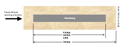
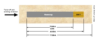
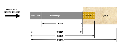
10 Paragraph 5.2.2.2, the diagrams
substitute
|
|
|
11 Paragraph 5.2.5.1
substitute
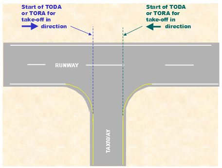
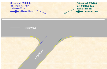
5.2.5.1 The following diagrams illustrate the method of calculating the take-off distance available or take-off run available where departures are allowed from taxiway intersections.
|
|
12 Paragraph 6.2.5.1
substitute
6.2.5.1 Where parallel runways are to be provided, the aerodrome operator should consult with CASA and Airservices Australia on airspace and air traffic control procedures associated with the operation of the multiple runways. Where parallel, non-instrument runways are provided for simultaneous use, the minimum separation distance between the runway centrelines must not be less than:
(a) where General Aviation Aerodrome Procedures (GAAP) are in place — 213m. If this distance is not provided, dependent parallel procedures may need to be introduced;
(b) where the higher code number of the two runways is 3 or 4 — 210m;
(c) where the higher code number of the two runways is 2 — 150m;
(d) where the code number of the two runways is 1 — 120m.
13 Paragraph 6.2.9.1
substitute
6.2.9.1 The surface of a bitumen seal, asphalt or concrete runway must not have irregularities that would result in the loss of frictional characteristics or otherwise adversely affect the take-off or landing of an aircraft.
Note: The finish of the surface of a runway should be such that, when tested with a 3m straight-edge placed anywhere on the surface, there is no deviation greater than 3mm between the bottom of the straight-edge and the surface of the runway pavement anywhere along the straight‑edge.
6.2.9.1A The surface of a bitumen seal, asphalt or concrete runway must have an average surface texture depth of not less than 1mm over the full runway width and runway length.
Note: A runway surface meeting the ICAO minimum design objective for new surfaces specified in Annex 14, Volume 1, derived using a continuous friction-measuring device, is acceptable.
14 Paragraph 6.2.10.2
substitute
6.2.10.2 CASA does not specify a standard for runway bearing strength, however, the bearing strength must be such that it will not cause any safety problems to aircraft. The published PCN value should be suitable for the aircraft that regularly use the runway.
15 Paragraph 6.2.29.1, the Note
substitute
Note: To reduce the risk of damage to an aeroplane undershooting the runway and to prevent jet blast erosion from jet aircraft turning and taking off at the end of the runway, it is recommended that areas abutting the runway should be provided with a compacted gravel pavement with a depth at the runway end equal to half the depth of the runway pavement, tapering to natural surface, the length of the taper being adjusted according to the bearing capacity of the natural surface. For areas beyond the gravel surface and outside the runway strip, graded but non-compacted natural surface with a grass cover is preferred. Hard pans should be broken up.
16 Paragraph 6.2.39.2
omit
accelerated (wherever occurring)
insert
accelerate
17 Paragraph 6.3.14.3
substitute
6.3.14.3 No portion of the taxiway strip beyond the graded portion, nor objects thereon, must project upwards through a plane surface, originating from the outer edge of the graded taxiway strip, sloping upwards and outwards at a slope of 5% measured with reference to the horizontal.
Note: The presence of drains and ditches in this part of the taxiway strip is acceptable.
18 Paragraph 6.4.4.2, contents of Table 6.4-1
substitute
Code number | Type of runway | ||||
Non-instrument | Non-precision approach | Precision category I | Precision category | Take–off | |
1 | 30m | 40m | 60m | – | 30m |
2 | 40m | 40m | 60m | – | 40m |
3 | 75ma | 75ma | 90mb | 105mc | 75ma |
4 | 75m | 75m | 90md | 105mc d | 75m |
a if the runway’s code is 3A, 3B or 3C, the minimum distance is 45m. b if the runway’s code is 3A, 3B or 3C, the minimum distance is 75m. c may be reduced to 90m up to 300 m from the runway end. d if the runway code letter is F, this distance should be 107.5m. | |||||
19 Paragraph 7.1.8.1
omit
Table 10.15-1
insert
Table 7.1-1
20 Paragraph 7.1.8.5
omit
Table 10.15-1
insert
Table 7.1-1
21 After subparagraph 7.3.2.5 (f)
insert
(g) The above surfaces are to be varied when lateral offset, offset or curved approaches are utilised, specifically, two sides originating at the ends of the inner edge and diverging uniformly at a specified rate from the extended centreline of the lateral offset, offset or curved ground track.
22 Paragraph 8.1.2.1, at the end
insert
Note: A closed aerodrome or aerodrome facility means one which has been withdrawn or decommissioned, not one which is temporarily unserviceable.
23 Paragraph 8.2.1.4, at the bottom of Figure 8.2-1
insert
For cones used as runway edge markers h = 0.3m, w = 0.4m
24 Paragraph 8.3.9.5
after
comprising white lines 1m wide.
insert
The number of 10m long arrowhead markings used should be commensurate with the width of the runway.
25 Paragraph 8.3.9.9, the diagram in Figure 8.3-15
substitute
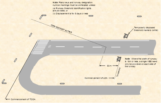
26 Paragraph 8.3.9.9, the diagram in Figure 8.3-16
substitute

27 Paragraph 8.4.3.4, diagram in Figure 8.4-2
substitute
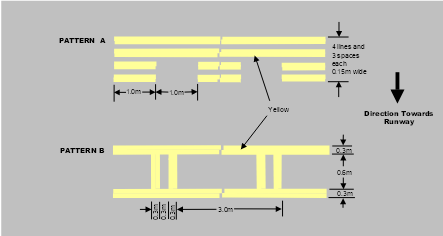
28 Paragraph 8.4.3.5, diagram in Figure 8.4-3
substitute
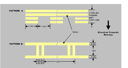
29 After paragraph 8.5.2.4
insert
8.5.2.5 Where an aircraft designator marking is required to cover a multiple number of aircraft types, and there is insufficient space for the marking, an abbreviated version of the designator may be used e.g. an A330-200 may be abbreviated to A332, a BAe 146‑200 to B462 and a B737-800 to B738. A list of typical aircraft designators is published by Airservices Australia on their web page: http://www.airservicesaustralia.com/pilotcentre/SpecialpilotOps/acft.pdf.
30 Paragraph 8.6.6.4
substitute
8.6.6.4 The average luminance of the sign must be calculated in accordance with ICAO Annex 14, Volume 1, Appendix 4, Figure 4.1.
31 Paragraph 8.7.1.2
substitute
8.7.1.2 CASR Part 139 also requires that non-precision approach runways be provided with a wind direction indicator at the threshold of the runway. However, subject to paragraph 8.7.1.3, for runways 1200m or less in length one centrally located wind direction indicator visible from both approaches and the aircraft parking area is acceptable.
32 Paragraph 8.10.2.4, diagram in Figure 8.10-2
substitute
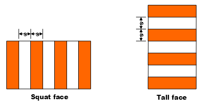
33 Paragraph 8.10.4.1
substitute
8.10.4.1 A vehicle used regularly on the manoeuvring area by day should be painted a single conspicuous colour, preferably yellow or orange. Where so painted, it does not require additional marking.
34 Paragraph 8.10.4.2
substitute
8.10.4.2 Vehicles not painted yellow or orange must be marked, by using either:
(a) flags; or
(b) vehicle warning lights, in accordance with paragraph 9.19.1.
35 Paragraph 9.1.15.6
omit all words from and including
“Information” to and including “NOTAM”
insert
Information to be supplied by aerodrome operator for inclusion in the permanent NOTAM
36 Subparagraph 9.9.1.4 (c)
substitute
Double-sided PAPI; and
37 Paragraph 9.9.1.5
omit
double sided (wherever occurring)
insert
double-sided
38 Paragraph 9.9.2.1
omit all words up to and including
provided.
insert
An obstacle assessment surface (OAS) must be surveyed and assessed for obstacles for each end of the runway where a T-VASIS, AT-VASIS, double‑sided PAPI or PAPI is to be provided.
39 Paragraph 9.9.4.4
substitute
9.9.4.4 A double-sided PAPI system must consist of eight light units symmetrically disposed about the runway centre line in the form of two wing bars of four light units each. The indications seen by the pilot must be symmetrical, so that when on or close to the approach slope, the two light units nearest the runway, in both wing bars, show red.
40 Paragraph 9.9.4.5
after
Siting a PAPI
insert
or a Double-sided PAPI
41 After subparagraph 9.10.17.1 (b)
insert
(c) with respect to taxiways intended for exiting the runway, be located such that an aircraft exiting the runway will not be required to cross the row of red lights comprising the runway end lights.
Note: The universally accepted convention in aerodrome lighting is that a pilot is never required to cross a row of red lights.
42 Paragraph 9.11.1.4, title to Figure 9.11-12
substitute
Figure 9.11-12: Method of Establishing Grid Points to be used for the Calculation of Average Intensity of Runway Lights specified by Figure 9.11-3 to Figure 9.11-10
43 After paragraph 9.13.13.3
insert
9.13.13.4 Where a taxiway intersects with a runway, the last taxiway edge lights should preferably line-up with the line of runway edge lights, and must not encroach beyond the line of runway edge lights into the area outlined by the runway edge lights.
44 Paragraph 9.13.18.1, paragraph (a) of the Note
substitute
(a) the centreline of lights in each pair should be separated by a horizontal distance that is not less than 2.5 times, and not more than 4 times, the radius of the individual lantern lens;
45 Paragraph 9.19.1.1
substitute
9.19.1.1 Vehicle warning lights, as required by subsection 10.9.2, are provided to indicate to pilots and others the presence of vehicles or mobile plant on the movement area.
46 Paragraph 9.20.1.1
omit
are to be (wherever occurring)
insert
must be
47 Paragraph 9.20.2.1
substitute
9.20.2.1 Any aerodrome light outage detected must be fixed as soon as is practicable. The specifications listed below are intended to define the maintenance performance level objectives. They are not intended to define whether the lighting system is operationally out of service. Nor are they meant to condone outage, but are intended to indicate when lighting outage must be notified to the NOTAM office. The specifications must be used as triggers for NOTAM action, to advise pilots of actual outage, unless the outage can be rectified before the next period of use.
48 Paragraph 9.20.2.5
substitute
9.20.2.5 A lighting system is deemed to be on outage when:
(a) in the case of a lighting system comprising less than 4 lights (e.g. intermediate holding position lights or runway threshold identification lights), any of the lights are on outage;
(b) in the case of a lighting system comprising 4 or 5 lights (e.g. wind direction indicator lights or runway guard lights), more than 1 light is on outage;
(c) in the case of a lighting system comprising 6 to 13 lights (e.g. threshold lights or LAHSO lights), more than 2 lights are on outage, or 2 adjacent lights are on outage;
(d) in the case of a lighting system comprising more than 13 lights, more than 15% of the lights are on outage, or two adjacent lights are on outage.
Note: A lighting system here means lights used to illuminate a particular facility e.g. all the lights used to mark a threshold or runway end, runway edge lights on a runway, taxiway lights on a length of taxiway between intersections a T–VASIS or a PAPI system.
49 Subparagraph 9.20.2.6 (d)
substitute
(d) Whenever a red filter has deteriorated such that it does not produce the correct colour light beam, is missing, or is damaged, all the lamps within the affected light unit must be extinguished until the red filter is rectified. The affected light unit is included as an outage light unit when applying (b) or (c) above.
50 Paragraph 9.20.2.7
substitute
9.20.2.7 For a PAPI, the outage standards take into account both the number of lamps on outage within a light unit and also the number of light units within the PAPI system. The standards are:
(a) a PAPI light unit is deemed on outage when more than one lamp in a 3 or more lamp light unit is on outage, or any lamp in a less-than-3-lamp light unit is on outage;
(b) whenever a red filter has deteriorated such that it does not produce the correct colour light beam, is missing, or is damaged, all the lamps associated with that filter must be extinguished until the red filter is rectified. The affected lamp/s are included as outage lamps when determining (a) above.
(c) a double-sided PAPI system (i.e. 8 light units) is:
(i) deemed to be on outage but useable when all light units in one wing bar are fully functioning, and any light units in the other wing bar are on outage. The system may remain in use but a NOTAM must be issued detailing the number of light units on outage, and on which side of the runway they are; and
(ii) deemed on outage when one or more light units in each wing bar is on outage. The double-sided PAPI system must be extinguished until the system is rectified;
(d) a single-sided PAPI system (i.e. 4 light units) is deemed to be on outage when any light unit is on outage. The PAPI system must be extinguished until the system is rectified.
51 After paragraph 10.8.1.4
insert
10.8.1.4A Where a rescue and fire fighting service (RFFS) is established at an aerodrome, the aerodrome operator and the rescue and fire fighting service provider must work together to ensure that they achieve the required outcome identified in MOS Part 139H – Standards Applicable to the Provision of Aerodrome Rescue and Fire Fighting Services.
52 Paragraph 10.8.7.1
substitute
10.8.7.1 The person who initially assumes co-ordination of the situation should hand over the role when police arrive.
53 Paragraph 10.9.2.5
substitute
10.9.2.5 Vehicles operating on the manoeuvring area by day must be marked in accordance with paragraph 8.10.4.
54 Paragraph 10.9.2.6
substitute
10.9.2.6 Vehicles operating on the movement area must:
(a) be lit with vehicle warning lights in accordance with paragraph 9.19.1, unless accompanied by a vehicle that is so equipped; and
(b) display dipped headlights at night or in conditions of poor visibility.
55 After paragraph 10.9.2.6
insert
10.9.2.7 Aircraft servicing equipment used only on aprons need not comply with paragraph 10.9.2.6. In this case, equipment is deemed to be mobile objects that do not have their own motive power.
56 Paragraph 10.10.4.2
substitute
10.10.4.2 Paragraph 10.10.4.1 does not apply at a controlled aerodrome or in other cases if the area can be restored to the required safety standards so as to allow aircraft operations to take place without delay.
57 Paragraph 10.10.7.4
substitute
10.10.7.4 A works safety officer must be present at all times if aerodrome works are being carried out and the aerodrome is open to aircraft operations.
58 After paragraph 10.10.7.4
insert
10.10.7.4A For time-limited works, a dedicated works safety officer is not required if one of the persons carrying out the time-limited work has been trained to perform the function of the works safety officer.
59 After paragraph 10.10.11.4
insert
10.10.11.5 Before a runway being overlaid is returned to a temporary operational status, a runway centreline marking conforming to the specifications in Chapter 8, Section 8.3, Subsection 8.3.3 must be provided.
60 Paragraph 10.11.9.1
substitute
10.11.9.1 When personnel and equipment are required to vacate the movement area for certain operations, specific mention of this fact must be made, e.g. “All personnel and equipment will clear runway strip 11/29 for air transport operations”.
61 Subparagraph 10.13.3.2 (b), at the end
insert
Note: Advice is given in the USA National Fire Protection Association (NFPA) standards on the requirements for fire extinguishers at aircraft parking positions. The NFPA web page is: http://www.nfpa.org/catalog/home/index.asp.
62 Paragraph 11.1.21
substitute
11.1.21 Automatic Weather Information Stations
11.1.21.1 The location and configuration of the Bureau of Meteorology (BoM) provided weather information station sites and their dial‑up phone numbers, and, as relevant, the VHF broadcast frequencies, are set out in the MET section of ERSA.
11.1.21.2 Current weather information from the site is also available by accessing the BoM internet site at: www.bom.gov.au.
63 Subparagraph 12.1.3.2 (d)
substitute
(d) any obstacles which may infringe the approach, take-off, transitional, inner horizontal or other surfaces nominated by the procedure designer;
64 Paragraph 12.1.6.1, Note
substitute
Note: A copy of Notification of Changes to Serviceability of a Registered Aerodrome to the NOTAM Office is shown in Section 12.2.
65 Paragraph 12.1.7.3
substitute
12.1.7.3 Where aerodrome works are carried out without closing the aerodrome, the aerodrome works safety procedures specified in Chapter 10: Section 10.10 for certified aerodromes are equally applicable to registered aerodromes.
66 Paragraph 12.1.8.3
omit
taker-of
insert
take-off
67 After subsection 12.1.8
insert
12.1.9 Reporting of Obstacles
12.1.9.1 If the aerodrome is served by an instrument approach procedure, any obstacles, or proposed construction, that may infringe the obstacle limitation surface of the aerodrome, or other areas nominated by the designer of the instrument approach procedure, are to be reported to the designer.
68 Section 12.2, Form title
substitute
Notification of Changes to Serviceability of a Registered Aerodrome
69 Subsection 13.1.1, the heading
omit
Introduction
insert
Commencement and Introduction
70 Paragraph 13.1.1.1
substitute
13.1.1.1 The Standards set out in this Chapter come into effect in accordance with paragraph 1.1.1.2B.
13.1.1.1A This Chapter sets out the minimum Standards for aerodromes used in CASR Part 121B operations, that is air transport operations in aeroplanes with a maximum take-off weight not exceeding 5,700kg. Although these smaller aircraft may use aerodromes which meet the Standards applicable to aerodromes with respect to regular public transport operations by aeroplanes with a maximum take-off weight in excess of 5700kg, the minimum aerodrome standards for operations by such smaller aircraft are those set out in this Chapter.
71 Paragraph 13.1.1.2
omit
CASR 121B
insert
CASR Part 121B
72 Paragraph 13.1.2.1, Table 13.1-1, the headings in columns 1 to 4
substitute
Runway and obstacle surfaces | Aeroplanes not exceeding 5,700kg by night | Aeroplanes not exceeding 5,700kg by day | Aeroplanes not exceeding 2,000kg by day |
73 Paragraph 13.1.2.1, Table 13.1-1, Runway strip width — graded
substitute
Runway strip width: – preferred graded
– minimum acceptable graded
– graded plus ungraded |
80m
45m
80m |
60m
45m
60m |
30 m
–
60m |
Runway strip transverse slope | 3.0% | 3.0% | 3.0% |
74 Paragraph 13.1.2.1, after Table 13.1-1
insert
Note: At aerodromes with 10m wide runways, the aircraft operator or pilot in command should take into account the effects of crosswind.
75 After paragraph 13.1.2.3
insert
13.1.2.3A Runway strip. The runway strip may consist of a graded portion and an ungraded portion in cases where it is impractical to grade the entire runway strip. The impracticability of complying with specified runway graded width requirements will depend on the circumstances of each individual case. Aerodrome operators should direct any questions about this issue to their nearest CASA area office.
76 Paragraph 13.1.3.3
substitute
![]()
![]()
![]() 13.1.3.3 On unsealed runways, where the runway strip is not maintained to the normal runway grading standards, the runway must be marked using cone markers. Where both the runway and the runway strip are prepared suitable for aircraft operations, either the runway or the runway strip may be marked. Where the runway is not marked using cone markers, the threshold locations should be marked using white cones appropriately positioned in the shape of a .
13.1.3.3 On unsealed runways, where the runway strip is not maintained to the normal runway grading standards, the runway must be marked using cone markers. Where both the runway and the runway strip are prepared suitable for aircraft operations, either the runway or the runway strip may be marked. Where the runway is not marked using cone markers, the threshold locations should be marked using white cones appropriately positioned in the shape of a .
Note: Where cone markers are used they may be held down using tent pegs or similar, provided the pegs do not pose a hazard to aircraft or compromise the frangibility of the marker.
77 After paragraph 13.1.3.5
insert
13.1.3.6 Where the edges of unsealed taxiways or aprons might not be visually clear to pilots, markers may be provided in accordance with Section 8.2.
78 Paragraph 13.1.4.1
substitute
13.1.4.1 Where a runway is intended for night operations, the runway must be provided with runway edge lighting, spaced laterally at 30 – 31m apart, and longitudinally at approximately 90m apart. The edge lights on each side must present two parallel straight rows equidistant from the runway centreline. The lights indicating both ends of the runway must be at right angles to the runway centreline. See Figure 13.1-4 for a typical layout of runway lights.
79 Paragraph 13.1.4.2
substitute
13.1.4.2 Where there is no permanent electricity supply, the following may be used:
(a) lights producing white light and powered by portable generators, batteries, or similar power sources; or
(b) flares.
