Attachment A to Appendix B
- Requirements
The Not To Exceed (NTE), Smoke or alternate Opacity limits stated in Table 2 of section 3 of Appendix B apply to engines when tested under conditions which can reasonably be expected to be encountered in normal vehicle operation and use. The limits apply when new and in-use throughout the useful life of the engine. In order to satisfy the NTE screening guidelines, the manufacturer must adhere to the requirements and protocols described in sections 2 and 3 of this Attachment A.
- NTE Requirements
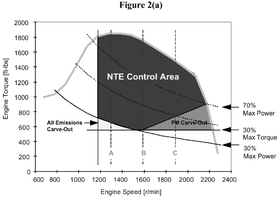
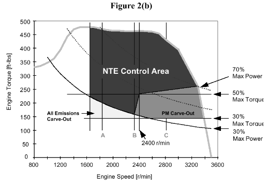
- Except as described in paragraph 2.1.2 below, the NTE Control Area includes all operating speeds above the "15% ESC Speed" calculated as in the following paragraph 2.1.1, and all engine load points at 30% or more of the maximum torque value produced by the engine (refer Figure 2(a) and Figure 2(b)). In addition, notwithstanding the provisions of paragraph 2.1.2, the NTE Control Area includes all operating speed and load points with brake specific fuel consumption (BSFC) values within 5% of the minimum BSFC value of the engine, unless during Certification the manufacturer demonstrates to the satisfaction of the ‘Administrator’ that the engine is not expected to operate at such points in normal vehicle operation and use. Current engine designs equipped with drivelines with multi-speed manual transmissions or automatic transmissions with a finite number of gears are not subject to the 5% minimum BSFC additional NTE region.
- The 15% ESC Speed is calculated using the formula n lo + 0.15(n hi - n lo ),
where n lo and n hi are the low and high engine speeds defined in Annex III, Appendix 1, Section 1.1 of Appendix A.
- The 15% ESC Speed is calculated using the formula n lo + 0.15(n hi - n lo ),
- Except as described in paragraph 2.1.2 below, the NTE Control Area includes all operating speeds above the "15% ESC Speed" calculated as in the following paragraph 2.1.1, and all engine load points at 30% or more of the maximum torque value produced by the engine (refer Figure 2(a) and Figure 2(b)). In addition, notwithstanding the provisions of paragraph 2.1.2, the NTE Control Area includes all operating speed and load points with brake specific fuel consumption (BSFC) values within 5% of the minimum BSFC value of the engine, unless during Certification the manufacturer demonstrates to the satisfaction of the ‘Administrator’ that the engine is not expected to operate at such points in normal vehicle operation and use. Current engine designs equipped with drivelines with multi-speed manual transmissions or automatic transmissions with a finite number of gears are not subject to the 5% minimum BSFC additional NTE region.
2.1.2 The area below 30% of the maximum power value produced by the engine is excluded from the NTE Control Area


2.2 Within the NTE Control Area, emissions of Oxides of Nitrogen (NOx), when averaged over a minimum time of 30 seconds, shall not exceed the applicable NTE limit values specified in Table 2 of Section 3 of Appendix B. In addition, within the NTE Control Area, smoke and opacity shall not exceed the applicable Smoke or alternate Opacity limit values specified in Table 2.
- The NTE and Smoke or alternate Opacity limit values apply to certification, production line and in-use engines.
- The engine must comply with the applicable NTE and Smoke or alternate Opacity limit values under all conditions which may reasonably be expected to be encountered in normal vehicle operation and use.
- The humidity correction factors found in 40 CFR Part 86 shall be used for NOx. Outside the temperature range of 20-30 oC, NOx emissions shall be corrected to 20 oC if below 20 oC, or to 30 oC if above 30 oC.
- Supplemental Emissions Test Smoke Measurements
Supplemental emission tests may use steady-state or transient smoke measurements. Steady-state smoke measurements may be conducted using opacimeters or filter-type smokemeters. Opacimeter types include partial-flow and full-flow. Only full-flow opacimeters may be used to measure smoke during transient conditions.
- For steady-state or transient smoke testing using full-flow opacimeters, equipment meeting the requirements of CFR 40, Part 86, subpart I “Emission Regulations for New Diesel Heavy-Duty Engines; Smoke Exhaust Test Procedure or ISO/DIS-11614 “Reciprocating internal combustion compression-ignition engines -Apparatus for measurement of the opacity and for determination of the light absorption coefficient of exhaust gas” is recommended.
- All full-flow opacimeter measurements shall be reported as the equivalent percent opacity for a 12.7 cm effective optical path length using the Beer-Lambert relationship.
- Zero and full-scale (100% opacity) span shall be adjusted prior to testing.
- Post test zero and full scale span checks shall be performed. For valid tests, zero and span drift between the pre-test and post-test checks shall be less than 2% of full scale.
- Opacimeter calibration and linearity checks shall be performed using manufacturer’s recommendations or good engineering practice.
- For steady-state testing using filter-type smokemeter, equipment meeting the requirements of ISO-8178-3 and ISO/FDIS-10054 “Internal combustion compression-ignition engines – Measurement apparatus for smoke from engines operating under steady-state conditions – Filter-type smokemeter” is recommended.
- All filter-type smokemeter results shall be reported as a filter smoke number (FSN) that is similar to the Bosch smoke number (BSN) scale.
- Filter-type smokemeters shall be calibrated every 90 days using manufacturer’s recommended practices or good engineering practice.
- For steady-state testing using partial-flow opacimeter, equipment meeting the requirements of ISO-8178- 3 and ISO/DIS-11614 is recommended.
- All partial-flow opacimeter measurements shall be reported as the equivalent percent opacity for a 12.7 cm effective optical path length using the Beer-Lambert relationship.
- Zero and full scale (100% opacity) span shall be adjusted prior to testing.
- Post test zero and full scale span checks shall be performed. For valid tests, zero and span drift between the pre-test and post-test checks shall be less than 2% of full scale.
- Opacimeter calibration and linearity checks shall be performed using manufacturer’s recommendations or good engineering practice.
- Replicate smoke tests may be run to improve confidence in single test or stabilization. If replicate tests are run, 3 additional valid test will be run, and the final reported test results must be the average of all the valid tests.
- A minimum of 30 seconds sampling time will be used for average transient smoke measurements.