
Vehicle Standard (Australian Design Rule 6/00 – Direction Indicators) 2005
I, JAMES ERIC LLOYD, Minister for Local Government, Territories and Roads, determine this vehicle standard under subsection 7 (1) of the Motor Vehicle Standards Act 1989.
Dated 21st November 2005
[SIGNED]
James Eric Lloyd
Minister for Local Government, Territories and Roads
CONTENTS
0.1. NAME OF STANDARD.........................................3
0.2. COMMENCEMENT............................................3
0.3. REPEAL......................................................3
1. SCOPE.......................................................3
2. APPLICABILITY AND IMPLIMENTATION.........................3
3. DEFINITIONS.................................................3
4. REQUIREMENTS..............................................3
5. EXEMPTIONS AND ALTERNATIVE PROCEDURES...............3
6. SUPPLEMENTARY GENERAL REQUIREMENTS..................4
7. ALTERNATIVE STANDARDS...................................4
8. NOTES.......................................................4
APPENDIX A.........................................................5
0.1. NAME OF STANDARD
0.1.1. This Standard is the Vehicle Standard (Australian Design Rule 6/00 – Direction Indicators) 2005.
0.1.2. This Standard may also be cited as Australian Design Rule 6/00 — Direction Indicators.
0.2. COMMENCEMENT
0.2.1. This Standard commences on the day after it is registered.
0.3. REPEAL
0.3.1. This Standard repeals each vehicle standard with the name Australian Design Rule 6/00 — Direction Indicators that is:
(a) made under section 7 of the Motor Vehicles Standard Act 1989; and
(b) in force at the commencement of this Standard.
0.3.2. This Standard also repeals each instrument made under section 7 of the Motor Vehicles Standard Act 1989 that creates a vehicle standard with the name Australian Design Rule 6/00 — Direction Indicators, if there are no other vehicle standards created by that instrument, or amendments to vehicle standards made by that instrument, that are still in force at the commencement of this Standard.
- SCOPE
This Australian Design Rule (ADR) prescribes the requirements for a device mounted on a motor vehicle or trailer which when operated by the driver signals the latter's intention to change the direction in which the vehicle is proceeding.
2. APPLICABILITY AND IMPLIMENTATION
2.1. The circumstances under which direction indicators are mandatory, optional, or prohibited are set out in either ADRs 13/..., 19/… or 67/….
3. DEFINITIONS
3.1. Refer to paragraph 1 of Appendix A.
4. REQUIREMENTS
4.1. Devices complying with the technical requirements of Appendix A as varied by part 5 Exemptions and Alternative Procedures and part 6 Supplementary General Requirements shall be accepted as complying with this design rule.
5. EXEMPTIONS AND ALTERNATIVE PROCEDURES
5.1. The following provisions of Appendix A do not apply to this rule:
5.1.1. Section 2 Application for approval
Section 3 Markings
Section 4 Approval
Section 9 Modifications of a type of direction indicator for motor vehicles and their trailers and extension of approval
Section 10 Conformity of production – partial (for particular deletions to the section refer to paragraphs 5.1.2 and 5.1.3)
Section 11 Penalties for non-conformity of production
Section 12 Production definitely discontinued
Section 13 Names and addresses of technical services responsible for conducting approval tests and of administrative departments
Section 14 Transitional provisions
Annex 1 Communication concerning the approval or extension or refusal or withdrawal of approval or production definitely discontinued of a type of direction indicator pursuant to Regulation No.6
Annex 2 Examples of arrangements of approval marks
5.1.2. The opening paragraph in Section 10, paragraph 10.4 and
5.1.3. Paragraphs 2.3 and 3.3 in Annex 7
6. SUPPLEMENTARY GENERAL REQUIREMENTS
The following general requirements are supplementary to the requirements of Appendix A:
6.1. The requirements and procedures set out in Annexes 6 and 7 of Appendix A are acceptable for the purposes of demonstrating compliance with the technical requirements of this rule.
7. ALTERNATIVE STANDARDS
7.1. The technical requirements of any of the editions of United Nations –Economic Commission for Europe (UN ECE) Regulation No. 6 - UNIFORM PROVISIONS CONCERNING THE APPROVAL OF DIRECTION INDICATORS FOR MOTOR VEHICLES AND THEIR TRAILERS, up to and including the edition incorporating the 01 series of amendments are deemed to be equivalent to the technical requirements of this rule.
8. NOTES
8.1. In place of Regulation No 48 where referenced in Appendix A, read ADR 13/00.
8.2. In place of Regulation No 37 where referenced in Appendix A, read ADR 51/00.
APPENDIX A
UN-ECE REGULATION NO. 6/01
UNIFORM PROVISIONS CONCERNING THE APPROVAL OF DIRECTION INDICATORS FOR MOTOR VEHICLES AND THEIR TRAILERS
Regulation No. 6
UNIFORM PROVISIONS CONCERNING THE APPROVAL OF DIRECTION INDICATORS FOR MOTOR VEHICLES AND THEIR TRAILERS
CONTENTS
REGULATION
- Definitions.
- Application for approval
- Markings
- Approval
- General specifications
- Intensity of light emitted
- Test procedure
- Colour of light emitted
- Modifications of a type of direction indicator for motor vehicles and their trailers and extension of approval
- Conformity of production
- Penalties for non-conformity of production
- Production definitely discontinued
- Names and addresses of technical services responsible for conducting approval tests, and of administrative departments
- Transitional provisions
ANNEXES
Annex 1 -Categories of direction indicators: Minimum angles required for light distribution in space of these categories of direction indicators
Annex 2 -Communication concerning the approval or extension or refusal or withdrawal of approval or production definitely discontinued of a type of direction indicator pursuant to Regulation No. 6
Annex 3 -Arrangement of the approval mark
Annex 4 -Photometric measurements
Annex 5 -Colour of amber lights - Trichromatic co-ordinates
Annex 6 -Minimum requirements for conformity of production control procedures
Annex 7 -Minimum requirements for sampling by an inspector
Regulation No. 6
UNIFORM PROVISIONS CONCERNING THE APPROVAL OF DIRECTION INDICATORS FOR MOTOR VEHICLES AND THEIR TRAILERS
1. DEFINITIONS
For the purposes of this Regulation:
1.1. "Direction indicator" means a device mounted on a motor vehicle or trailer which, when operated by the driver, signals the letter's intention to change the direction in which the vehicle is proceeding. The present Regulation applies solely to fixed-position flashing light devices whose flashing is obtained by the intermittent supply of electric current to the lamp.
1.2. The definitions given in Regulation No. 48 and its series of amendments in force at the time of application for type approval shall apply to this Regulation.
1.3. "Direction indicators of different 'types' " are different indicators which differ in such essential respects as:
The trade name or mark,
The characteristics of the optical system (levels of intensity, light distribution angles, etc.),
The category of direction indicators,
The colour of the filament lamp.
2. APPLICATION FOR APPROVAL
2.1. The application for approval of a type of direction indicator shall be submitted by the holder of the trade name or mark or by his duly accredited representative. It shall specify to which category or to which of the categories 1, 1 a, 1 b, 2a, 2b, 3, 4, 5 or 6 according to Annex 1, the direction indicator belongs and, if it belongs to category 2, whether it has one level of intensity (category 2a) or two levels of intensity (category 2b) and whether the direction indicator may also be used in an assembly of two lamps of the same category.
2.2. For each type of direction indicator the application shall be accompanied by the following:
2.2.1. Drawings, in triplicate, sufficiently detailed to permit identification of the type and category and showing geometrically in what position the direction indicator is mounted on the vehicle; the axis of observation to be taken as the axis of reference in the tests (horizontal angle H = 0 degrees , vertical angle V = 0 degrees ); and the point to be taken as the centre of reference in the said tests. The drawings shall show the position intended for the approval number and the additional symbols in relation to the circle of the approval mark;
2.2.2. A brief technical description stating in particular the categories of filament lamps prescribed, with the exception of lamps with non-replaceable light sources; each filament lamp category shall be one or other of those contained in Regulation No. 37;
2.2.3. For a direction indicator of category 2b, an arrangement diagram and a specification of the characteristics of the system ensuring the two levels of intensity;
2.2.4. Two samples; if the approval is applied for devices which are not identical but are symmetrical and suitable for mounting one on the left and one on the right side of the vehicle, the two samples submitted may be identical and be suitable for mounting only on the right or only on the left side of the vehicle; for a direction indicator of category 2b, the application shall also be accompanied by two samples of the parts constituting the system which ensures the two levels of intensity.
3. MARKINGS
Devices submitted for approval shall:
3.1. bear the trade name or mark of the applicant; this marking shall be clearly legible and indelible;
3.2. bear a clearly legible and indelible marking indicating the category or categories of filament lamps prescribed; this is not valid for lamps with non-replaceable light sources;
3.3. comprise a space of sufficient size for the approval marking and the additional symbols prescribed in paragraph 4.2. below; this space shall be shown in the drawings mentioned in paragraph 2.2.1. above;
3.4. in the case of lamps with non-replaceable light sources, bear the marking of rated voltage and rated wattage.
4. APPROVAL
4.1. General
4.1.1. If the two devices submitted for approval in pursuance of paragraph 2.2.4. above meet the requirements of this Regulation, approval shall be granted.
4.1.2. Where grouped, combined or reciprocally incorporated lamps have been found to comply with the requirements of several Regulations annexed to the 1958 Agreement, a single international approval mark may be applied provided that such lamps are not grouped, combined or reciprocally incorporated with a lamp or lamps not satisfying any one of these Regulations.
4.1.3. An approval number shall be assigned to each type approved. Its first two digits (at present 01, corresponding to the 01 series of amendments which entered into force on 27 June 1987) shall indicate the series of amendments incorporating the most recent major technical amendments made to the Regulation at the time of issue of the approval. The same Contracting Party shall not assign the same number to another type of device covered by this Regulation. Direction indicators of different categories may be marked with a single approval number when they form one assembly.
4.1.4. Notice of approval or of extension or refusal or withdrawal of approval or production definitely discontinued of a type of device pursuant to this Regulation shall be communicated to the Parties to the 1958 Agreement which apply this Regulation, by means of a form conforming to the model in Annex 2 to this Regulation.
4.1.5. Every device conforming to a type approved under this Regulation shall bear in the space referred to in paragraph 3.3. above, and in addition to the markings prescribed in paragraphs 3.1. and 3.2. or 3.4. respectively, an approval mark as described in paragraphs 4.2. and 4.3. below.
4.2. Composition of the approval mark
The approval mark shall consist of:
4.2.1. an international approval marking, comprising
4.2.1.1. A circle surrounding the letter "E" followed by the distinguishing number of the country which has granted approval;
4.2.1.2. The approval number prescribed in paragraph 4.1.3. above.
4.2.2. The following additional symbol (or symbols):
4.2.2.1. One or more of the numbers: 1, 1a, 1b, 2a, 2b, 3, 4, 5 or 6, according to whether the device belongs to one or more categories 1, 1a, 1b, 2a, 2b, 3, 4, 5 or 6 for which approval is sought in accordance with paragraph 2.1;
4.2.2.2. On devices which cannot be mounted on either side of the vehicle indiscriminately, an arrow showing in which position the device is to be mounted (the arrow shall be directed outwards from the vehicle in the case of devices of categories 1, 1 a, 1 b, 2a and 2b and towards the front of the vehicle in the case of devices of categories 3, 4, 5 and 6).
In addition, for devices of category 6 an indication "R" or "L" shall in this case be shown on the device, indicating the right or left side of the vehicle;
4.2.2.3. On devices which may be used as a single lamp and as part of an assembly of two lamps, the additional letter "D" to the right side of the symbol mentioned in paragraph 4.2.2.1.;
4.2.2.4. The two digits of the approval number which indicate the series of amendments in force at the time of issue of the approval and, if necessary, the required arrow may be marked close to the above additional symbols;
4.2.2.5. The marks and symbols referred to in paragraphs 4.2.1. and 4.2.2. above shall be clearly legible and be indelible even when the device is fitted in the vehicle.
4.3. Arrangement of the approval mark
4.3.1. Independent lamps
Annex 3, Figure 1, to this Regulation gives an example of arrangement of the approval mark with the above-mentioned additional symbols.
4.3.2. Grouped. combined or reciprocallv incorporated lamps
4.3.2.1. Where grouped, combined or reciprocally incorporated lamps have been found to comply with the requirements of several Regulations, a single international approval mark may be applied consisting of a circle surrounding the letter "E" followed by the distinguishing number of the country which has granted the approval, and an approval number. This approval mark may be located anywhere on the grouped, combined or reciprocally incorporated lamps, provided that:
4.3.2.1.1. it is visible after the installation of the lamps;
4.3.2.1.2. no part of the grouped, combined or reciprocally incorporated lamps that transmits light can be removed without at the same time removing the approval mark.
4.3.2.2. an identification symbol for each lamp appropriate to each Regulation under which approval has been granted, together with the corresponding series of amendments incorporating the most recent major technical amendments to the Regulation at the time of issue of the approval and, if necessary, the required arrow shall be marked:
4.3.2.2.1. either on the appropriate light-emitting surface;
4.3.2.2.2. or in a group, in such a way that each lamp of the grouped, combined or reciprocally incorporated lamps may be clearly identified.
4.3.2.3. The size of the components of a single approval mark shall not be less than the minimum size required for the smallest of the individual marks by the Regulation under which approval has been granted.
4.3.2.4. An approval number shall be assigned to each type approved. The same Contracting Party may not assign the same number to another type of grouped, combined or reciprocally incorporated lamps covered by this Regulation.
4.3.2.5. Annex 3, Figure 2, to this Regulation gives examples of the arrangement of the approval marks for grouped, combined or reciprocally incorporated lamps with all the above- mentioned additional symbols.
4.3.3. Lamps reciprocally incorporated with other lamps. of which the lens may also be used for other types of headlamps
The provisions laid down in paragraph 4.3.2. above are applicable.
4.3.3.1. In addition, where the same lens is used, the latter may bear the different approval marks relating to the different types of headlamps or units of lamps, provided that the main body of the headlamp, even if it cannot be separated from the lens, also comprises the space described in paragraph 3.3. above and bears the approval marks of the actual functions.
If different types of headlamps comprise the same main body, the latter may bear the different approval marks.
4.3.3.2. Annex 3, Figure 3, to this Regulation gives examples of approval marks for lamps reciprocally incorporated with a headlamp.
5. GENERAL SPECIFICATIONS
5.1. Each device supplied shall conform to the specifications set forth in paragraphs 6. and 8. below.
5.2. The devices must be so designed and constructed that under normal conditions of use and notwithstanding the vibrations to which they may be subjected in such use, their satisfactory operation remains assured and they retain the characteristics prescribed by this Regulation.
6. INTENSITY OF LIGHT EMITTED
6.1. The light emitted by each of the two devices supplied must be in the case of direction indicators of categories 1, 1a, 1b, 2a, 2b, 3 or 4 in the reference axes, in the case of direction indicators of categories 5 or 6 in direction A according to Annex 1 of not less than the minimum intensity and of not more than the maximum intensity specified below:


2/ The installation of front direction indicators of the various categories in power-driven vehicles and their trailers is provided for in the Regulations concerning the installation of lighting and light-signalling devices (Regulations Nos. 48 and 53).
3/ In the case of a single lamp containing more than one light source: the lamp shall comply with the minimum intensity required when any one light source has failed, however for front or rear direction indiator lamps 50% of the minimum intensity in the axis of reference of the lamp shall be considered sufficient provided that a note in the communication form states that the lamp is only for use on a vehicle fitted with an operating tell-tale which indicates when any one or more light source(s) has (have) failed, and when all light sources are illuminated the maximum intensity specified for a single lamp may be exceeded provided that the single lamp is not marked ''D'' and the maximum intensity specified for an assembly of two lamps (last column of the table) is not exceeded.
6.2. Outside the reference axis, within the angular fields specified in the arrangement diagrams in Annex 1 to this Regulation, the intensity of the light emitted by each of the two devices supplied must:
6.2.1. In each direction corresponding to the points in the relevant table of luminous-intensity distribution reproduced in Annex 4 to this Regulation, be not less than the minimum specified in paragraph 6.1. above multiplied by the percentage specified in the said table for the direction in question;
6.2.1.1. In divergence from paragraphs 6.2. and 6.2.1., for categories 4 and 5 direction indicators, to the rear, a minimum value of 0.6 cd is required throughout the fields specified in Annex 1;
6.2.2. In no direction within the area from which the indicator lamp is visible, exceed the maximum specified in paragraph 6.1. above;
6.2.3. Moreover,
6.2.3.1. Throughout the fields defined in the diagrams in Annex 1, the intensity of the light emitted must be not less than 0.7 cd for devices of category 1 b, not less than 0.3 cd for devices of categories 1, 1a, 2a, 3, 4 towards the front and for those of category 2b by day; it shall not be less than 0.07 cd for devices of category 2b by night;
6.2.3.2. For devices of categories 1 and 2b by night and, to the front, for devices of categories 3 and 4, the intensity of the light emitted outside the zone defined by the measuring points +/- 10 degrees H and +/- 10 degrees V (10 degrees -field) must not exceed the following values:
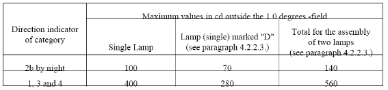
Between the boundaries of the 10 degrees -field (+/- 10 degrees H and +/- 10 degrees V) and the 5 degrees -field (+/- 5 degrees H and +/- 5 degrees V), the maximum admissible values of the intensities are linearly increased up to the values as defined in paragraph 6.1.;
6.2.3.3. For devices of category 1a and 1 b, the intensity of the light emitted outside the zone defined by the measuring points +/- 15 degrees H and +/- 15 degrees V (15 degrees - field) shall not exceed the following values:
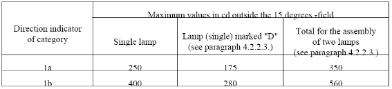
Between the boundaries of the 15 degrees -field (+/- 15 degrees H and +/- 15 degrees V) and the 5 degrees -field (+/- 5 degrees H and +/- 5 degrees V), the maximum values are increased linearly up to the values as defined in paragraph 6.1.
6.2.3.4. The provisions of paragraph 2.2. of Annex 4 to this Regulation on local variations of intensity must be observed.
6.3. The intensities shall be measured with the filament lamp(s) continuously alight.
6.4. In the case of devices of category 2b the time that elapses between electrical supply being switched on and the light output measured on the reference axis to reach 90% of the value measured in accordance with paragraph 6.3. above shall be measured for both the day and the night conditions of use. The time measured for the night condition of use shall not exceed that measured for the day condition of use.
6.5. Annex 4, referred to in paragraph 6.2.1. above, gives particulars of the measurement methods to be used.
7. TEST PROCEDURE
7.1. All measurements shall be made with an uncoloured or amber-coloured standard filament lamp of the category prescribed for the device, the supply voltage being so regulated as to produce the reference luminous flux prescribed for that category of lamp.
7.1.1. All measurements on lamps equipped with non-replaceable light sources (filament lamps and other) shall be made at 6.75 V, 13.5 V or 28.0 V respectively.
In the case of light sources supplied by a special power supply, the above test voltages shall be applied to the input terminals of that power supply. The test laboratory may require from the manufacturer the special power supply needed to supply the light sources.
7.2. However, in the case of an indicator of category 2b for which an additional system is used to obtain the night-time intensity, the voltage applied to the system for measuring the night-time intensity shall be that which was applied to the filament lamp for measuring the day-time intensity.
7.3. The vertical and horizontal outlines of the illuminating surface of a light-signalling device (paragraph 1.2.2.) shall be determined and measured in relation to the centre of reference (paragraph 1.2.5.).
8. COLOUR OF LIGHT EMITTED
The colour of the light emitted shall be within the limits of the co-ordinates prescribed in Annex 5 to this Regulation.
9. MODIFICATIONS OF A TYPE OF DIRECTION INDICATOR FOR MOTOR VEHICLES AND THEIR TRAILERS AND EXTENSION OF APPROVAL
9.1. Every modification of a type of direction indicator shall be notified to the administrative department which approved the type. The department may then either:
9.1.1. Consider that the modifications made are unlikely to have an appreciable adverse effect and that in any case the device still complies with the requirements; or
9.1.2. Require a further test report from the technical service responsible for conducting the tests.
9.2. Confirmation or refusal of approval, specifying the alterations, shall be communicated by the procedure specified in paragraph 4.1.4. above to the Parties to the Agreement applying this Regulation.
9.3. The competent authority issuing the extension of approval shall assign a series number for such an extension and inform thereof the other Parties to the 1958 Agreement applying this Regulation by means of a communication form conforming to the model in Annex 2 to this Regulation.
10. CONFORMITY OF PRODUCTION
The conformity of production procedures shall comply with those set out in the Agreement, Appendix 2 (E/ECE/324-E/ECE/TRANS/505/Rev. 2), with the following requirements:
10.1. Direction indicators approved under this Regulation shall be so manufactured as to conform to the type approved by meeting the requirements set forth in paragraphs 6 and 8 above.
10.2. The minimum requirements for conformity of production control procedures set forth in Annex 6 to this Regulation shall be complied with.
10.3. The minimum requirements for sampling by an inspector set forth in Annex 7 to this Regulation shall be complied with.
10.4. The authority which has granted type approval may at any time verify the conformity control methods applied in each production facility. The normal frequency of these verifications shall be once every two years.
11. PENALTIES FOR NON-CONFORMITY OF PRODUCTION
11.1. The approval granted in respect of a device pursuant to this Regulation may be withdrawn if the foregoing requirements are not met.
11.2. If a Contracting Party to the Agreement which applies this Regulation withdraws an approval it has previously granted, it shall forthwith so notify the other Contracting Parties applying this Regulation, by means of a communication form conforming to the model in Annex 2 to this Regulation.
12. PRODUCTION DEFINITELY DISCONTINUED
If the holder of the approval completely ceases to manufacture a device approved in accordance with this Regulation, he shall so inform the authority which granted the approval. Upon receiving the relevant communication, that authority shall inform thereof the other Parties to the 1958 Agreement applying this Regulaffon by means of a communication form conforming to the model in Annex 2 to this Regulation.
13. NAMES AND ADDRESSES OF TECHNICAL SERVICES RESPONSIBLE FOR CONDUCTING APPROVAL TESTS, AND OF ADMINISTRATIVE DEPARTMENTS
The Parties to the 1958 Agreement which apply this Regulation shall communicate to the United Nations Secretariat the names and addresses of the technical services responsible for conducting approval tests and of the administrative departments which grant approval and to which forms certifying approval or extension or refusal or withdrawal of approval, issued in other countries, are to be sent.
14. TRANSITIONAL PROVISIONS
14.1. As from the date of entry into force of the 01 series of amendments to this Regulation,
no Contracting Party applying it shall refuse to grant approvals under this Regulation as amended by the 01 series of amendments.
14.2. As from 36 months after the date of entry into force referred to in paragraph 14.1. above, Contracting Parties applying this Regulation shall grant approvals only if the type of light-signalling device corresponds to the requirements of this Regulation as amended by the 01 series of amendments.
14.3. Front direction indicators of categories 1a and 1b as described in paragraph 6.1. of this Regulation as amended may not be required until three years after the date of entry into force of this Regulation and then only for new vehicle types for which approval according to Regulation No. 48 is requested for a new design or a change of design and/ or of the shape of the bodywork affecting the dimensions of the front direction indicators and their position in relation to the passing lamps or fog lamps. Approvals granted to direction indicators of categories 4 and 5 under this Regulation in its original form, unamended, shall cease to be valid five years after the entry into force of the 01 series of amendments to this Regulation, unless the Contracting Party which granted approval notifies the other Contracting Parties applying this Regulation to the effect that the type of direction indicator approved also meets the requirements of this Regulation as amended by the 01 series of amendments.
14.4. The Parties to the Agreement applying this Regulation:
14.4.1. Shall continue after the date referred to above to recognize approvals granted in accordance with the original version of this Regulation for the fitting of replacement devices to vehicles in use;
14.4.2. May issue approvals for devices on the basis of the original version of this Regulation, provided that the devices are intended as replacements for fitting to vehicles in use and that it is not technically feasible for the devices in question to satisfy the new requirements contained in the 01 series of amendments.
14.5. Approvals which were granted to direction indicators of categories 1, 2a, 2b and 3 pursuant to this Regulation in its original form (00 series) until the date referred to in paragraph 14.2. shall remain valid after this date.
Annex 1
CATEGORIES OF DIRECTION INDICATORS:
MINIMUM ANGLES REQUIRED FOR LIGHT DISTRIBUTION IN SPACE OF THESE CATEGORIES OF DIRECTION INDICATORS
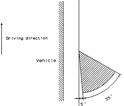
In all cases, the minimum vertical angles of light distribution in space of direction indicators are 15 degrees above and 15 degrees below the horizontal, in the case of direction indicators of category 6 however they are 30 degrees above and 5 degrees below the horizontal.
Minimum horizontal angles of light distribution in space:
Categories 1, 1 a and 1 b: direction indicators for the front of the vehicle:
Category 1: for use at a distance not less than 40 mm from the headlamp;
Category 1a: for use at a distance greater than 20 mm but less than 40 mm from the headlamp;
Cateqory 1b: for use at a distance less than 20 mm from the headlamp.

Category 2a: Direction indicators with one level of intensity for the rear of the vehicle.
Category 2b: Direction indicators with two levels of intensity for the rear of the vehicle.

Category 3: Front-side direction indicators for use on a vehicle equipped with this category of direction indicator only.

Category 4: Front-side direction indicators for use on a vehicle also equipped with category 2a or 2b direction indicators.

Cateaories 5 and 6: Supplementary side direction indicators for use on a vehicle also equipped with categories 1, 1a or 1 b and 2a or 2b direction indicators.

1/ Distinguishing number of the country which has granted/extended/refused/withdrawn approval (see approval provisions in the Regulation).
2/ Strike out what does not apply.
3/ For lamps with non-replaceable light sources indicate the number and the total wattage of the light sources.
Annex 3
ARRANGEMENT OF THE APPROVAL MARK
Figure 1

The device bearing the approval marking shown above is a category-4 device (front-side direction indicator) approved in Italy (E3) under No. 216, which may also be used in an assembly of two lamps. The arrow shows in what position this device, which cannot be mounted on either side of the vehicle indiscriminately, is to be mounted. The arrow points towards the front of the vehicle.
The number mentioned close to the symbol '4 D' indicates that the approval was granted according to the requirements of Regulation No. 6 as amended by the 01 series of amendments.
Direction in which the arrows on the approval mark point, according to the category of the device is shown below:

Note: The approval number and the additional symbols shall be placed close to the circle and either above or below the letter 'E', or to the right or left of that letter. The digits of the approval number shall be on the same side of the letter 'E' and face the same direction. The use of Roman numerals as approval numbers should be avoided so as to prevent any confusion with other symbols.
Simplified marking of grouped, combined or reciprocally incorporated lamps when two or more lamps are part of the same assembly
Figure 2
The vertical and horizontal lines schematize the shape of the light-signalling device. These are not part of the approval mark.

Note: The three examples of approval marks shown above (models A, B and C) represent three possible variables for the marking of a lighting device when two or more lamps are part of the same assembly of grouped, combined or reciprocally incorporated lamps.
They indicate that the device was approved in the Netherlands (E4-) under number 3333 and comprise:
a reflex-reflector of class IA approved in accordance with the 02 series of amendments to Regulation No. 3; a rear direction indicator of category 2a approved in accordance with the 01 series of amendments to Regulation No. 6;
a red rear position lamp (R) approved in accordance with the 01 series of amendments to Regulation No. 7;
a rear fog lamp (F) approved in accordance with Regulation No. 38 in its original version;
a reversing lamp (AR) approved in accordance with Regulation No. 23 in its original version;
a stop lamp with two levels of illumination (S2) approved in accordance with the 01 series of amendments to Regulation No. 7.

Note: The three examples shown above correspond to a lighting device bearing an approval mark relating to: a front position lamp approved in accordance with the 01 series of amendments to Regulation No. 7;
a headlamp with a passing beam designed for right-hand and left-hand traffic and a driving beam with a maximum intensity comprised between 86,250 and 101,250 candelas, approved in accordance with the 02 series of amendments to Regulation No. 20;
a front fog lamp approved in accordance with the 02 series of amendments to Regulation No. 19;
a front direction indicator lamp of category 1a approved in accordance with the 01 series of amendments to Regulation No.6.
Lamp reciprocally incorporated with a headlamp
Figure 3

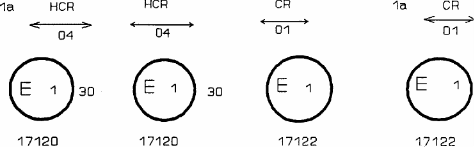
The above example corresponds to the marking of a lens intended to be used in different types of headlamps, namely:
either:
a headlamp with a passing beam designed for right-hand and left-hand traffic and a driving beam with a maximum intensity comprised between 86,250 and 101,250 candelas, approved in Germany (E1) in accordance with the requirements of Regulation No. 8 as amended by the 04 series of amendments; which is reciprocally incorporated with a front direction indicator approved in accordance with the 01 series of amendments to Regulation No. 6;
or:
a headlamp with a passing beam designed for right-hand and left-hand traffic and a driving beam, approved in Germany (E1) in accordance with the requirements of Regulation No. 1 as amended by the 01 series of amendments, which is reciprocally incorporated with the same front direction indicator as above; or even: either of the above-mentioned headlamps approved as a single lamp.
The main body of the headlamp shall bear the only valid approval number, for instance:
Annex 4
PHOTOMETRIC MEASUREMENTS
1. Measurement methods
1.1. During photometric measurements, stray reflections shall be avoided by appropriate masking.
1.2. In case the results of measurements should be challenged, measurements shall be carried out in such a way as to meet the following requirements:
1.2.1. The distance of measurement shall be such that the law of the inverse of the square of the distance is applicable;
1.2.2. The measuring equipment shall be such that the angular aperture of the receiver viewed from the reference centre of the light is comprised between 10' and 1 degree;
1.2.3. The intensity requirement for a particular direction of observation shall be deemed to be satisfied if that requirement is met in a direction deviating by not more than one - quarter of a degree from the direction of observation.
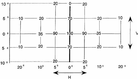
2. Table of standard light distribution in space for direction indicators of the categories 1, 1 a. 1 b, 2a, 2b 3. 4 and 5
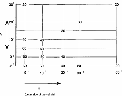
For direction indicators of category 6
2.1. The direction H = 0 degrees and V = 0 degrees corresponds to the reference axis. (On the vehicle, it is horizontal, parallel to the median longitudinal plane of the vehicle and oriented in the required direction of visibility.) It passes through the centre of reference. The values shown in the tables give, for the various directions of measurement, the minimum intensities as a percentage of the minimum intensities required in the table in paragraph 6.1.:
2.1.1. in the direction H = 0 degrees and V = 0 degrees for categories 1, 1a, 1b, 2a, 2b, 3 and in the case of category 4 to the front only;
2.1.2. in the direction H = 5 degrees and V = 0 degrees for category 6.
2.2. Within the field of light distribution of paragraph 2., schematically shown as a grid, the light pattern should be substantially uniform, i.e. in so far as the light intensity in each direction of a part of the field formed by the grid lines shall meet at least the lowest minimum value being shown on the grid lines surrounding the questioned direction as a percentage.
3. Photometric measurement of lamps equipped with several light sources
The photometric performance shall be checked:
3.1. For non-replaceable light sources (filament lamps and other):
with the light sources present in the lamp, in accordance with paragraph 7.1.1 of this Regulation.
3.2. For replaceable filament lamps:
when equipped with mass production filament lamps at 6.75 V, 13.5 V or 28.0 V, the luminous intensity values produced shall lie between the maximum limit given in this Regulation and the minimum limit of this Regulation increased according to the permissible deviation of the luminous flux permitted for the type of filament lamp chosen, as stated in Regulation No. 37 for production of filament lamps; altematively a standard filament lamp may be used in turn, in each of the individual positions, operated at its reference flux, the individual measurements in each position being added together.
Annex 5
COLOUR- OF AMBER LIGHTS:
TRICHROMATIC CO-ORDINATES
Limit towards yellow: y<0.429
Limit towards red: y>0.398
Limit towards white: z<0.007
For checking these colorimetric characteristics, a source of light at a colour temperature of 2,856 K corresponding to illuminant A of the International Commission on Illumination (CIE) shall be used in conformity with the Convention on Road Traffic (E/ CONF.56/16/Rev.1).
However, for lamps equipped with non-replaceable light sources (filament lamps and other), the colorimetric characteristics should be verified with the light sources present in the lamp, in accordance with paragraph 7.1.1 of this Regulation.
Annex 6
MINIMUM REQUIREMENTS FOR CONFORMITY OF PRODUCTION CONTROL PROCEDURES
1. GENERAL
1.1. The conformity requirements shall be considered satisfied from a mechanical and geometric standpoint, if the differences do not exceed inevitable manufacturing deviations within the requirements of this Regulation.
1.2. With respect to photometric performances, the conformity of mass-produced direction indicators shall not be contested if, when testing photometric performances of any direction indicator chosen at random and equipped with a standard filament lamp, or when the direction indicators are equipped with non-replaceable light sources (filament lamps or other), and when all measurements are made at 6.75 V, 13.5 V or 28.0 V respectively:
1.2.1. no measured value deviates unfavourably by more than 20% from the values prescribed in this Regulation.
1.2.2. If, in the case of a direction indicator equipped with a replaceable light source and if results of the test described above do not meet the requirements, tests on direction indicators shall be repeated using another standard filament lamp.
1.3. The chromaticity coordinates shall be complied with when the direction indicator is equipped with a standard filament lamp, or for direction indicators equipped with non- replaceable light sources (filament lamps or other), when the colorimetric characteristics are verified with the light source present in the direction indicator.
2. MINIMUM REQUIREMENTS FOR VERIFICATION OF CONFORMITY BY THE MANUFACTURER
For each type of direction indicator the holder of the approval mark shall carry out at least the following tests, at appropriate intervals. The tests shall be carried out in accordance with the provisions of this Regulation.
If any sampling shows non-conformity with regard to the type of test concerned, further samples shall be taken and tested. The manufacturer shall take steps to ensure the conformity of the production concerned.
2.1. Nature of tests
Tests of conformity in this Regulation shall cover the photometric and colorimetric characteristics.
2.2. Methods used in tests
2.2.1. Tests shall generally be carried out in accordance with the methods set out in this Regulation.
2.2.2. In any test of conformity carried out by the manufacturer, equivalent methods may be used with the consent of the competent authority responsible for approval tests. The manufacturer is responsible for proving that the applied methods are equivalent to those laid down in this Regulation.
2.2.3. The application of paragraphs 2.2.1. and 2.2.2. requires regular calibration of test apparatus and its correlation with measurements made by a competent authority.
2.2.4. In all cases the reference methods shall be those of this Regulation, particularly for the purpose of administrative verification and sampling.
2.3. Nature of sampling
Samples of direction indicators shall be selected at random from the production of a uniform batch. A uniform batch means a set of direction indicators of the same type, defined according to the production methods of the manufacturer.
The assessment shall in general cover series production from individual factories. However, a manufacturer may group together records concerning the same type from several factories, provided these operate under the same quality system and quality management.
2.4. Measured and recorded photometric characteristics
The sampled direction indicator shall be subjected to photometric measurements for the minimum values at the points listed in Annex 4, and the chromaticity coordinates listed in Annex 5, provided for in the Regulation.
2.5. Criteria governing acceptability
The manufacturer is responsible for carrying out a statistical study of the test results and for defining, in agreement with the competent authority, criteria governing the acceptability of his products in order to meet the specifications laid down for verification of conformity of products in paragraph 10.1. of this Regulation.
The criteria governing the acceptability shall be such that, with a confidence level of 95%, the minimum probability of passing a spot check in accordance with Annex 7 (first sampling) would be 0.95.
Annex 7
MINIMUM REQUIREMENTS FOR SAMPLING BY AN INSPECTOR
1. GENERAL
1.1. The conformity requirements shall be considered satisfied from a mechanical and a geometric standpoint, in accordance with the requirements of this Regulation, if any, if the differences do not exceed inevitable manufacturing deviations.
1.2. With respect to photometric performance, the conformity of mass-produced direction indicators shall not be contested if, when testing photometric performances of any direction indicator chosen at random and equipped with a standard filament lamp, or when the lamps are equipped with non-replaceable light sources (filament lamps or other), and when all measurements are made at 6.75 V, 13.5 V or 28.0 V respectively:
1.2.1. no measured value deviates unfavourably by more than 20% from the values prescribed in this Regulation.
1.2.2. If, in the case of a direction indicator equipped with a replaceable light source and if results of the test described above do not meet the requirements, tests on direction indicators shall be repeated using another standard filament lamp.
1.2.3. Direction indicators with apparent defects are disregarded.
1.3. The chromaticity coordinates shall be complied with when the direction indicator is equipped with a standard filament lamp, or for direction indicators equipped with non- replaceable light sources (filament lamps or other), when the colorimetric characteristics are verified with the light source present in the direction indicator.
2. FIRST SAMPLING
In the first sampling four direction indicators are selected at random. The first sample of two is marked A, the second sample of two is marked B.
2.1. The conformity is not contested
2.1.1. Following the sampling procedure shown in Figure 1 of this Annex the conformity of mass-produced direction indicators shall not be contested if the deviation of the measured values of the direction indicators in the unfavourable directions are:
2.1.1.1. sample A
A1:one direction indicator ........................................................................0%
one direction indicator not more than ......................................................20%
A2:both direction indicators more than ....................................................0%
but not more than .....................................................................................20%
go to sample B
2.1.1.2. sample B
B1: both direction indicators.....................................................................0%
2.1.2. or if the conditions of paragraph 1.2.2. for sample A are fulfilled.
2.2. The conformity is contested
2.2.1. Following the sampling procedure shown in Figure 1 of this Annex the conformity of mass-produced direction indicators shall be contested and the manufacturer requested to make his production meet the requirements (alignment) if the deviations of the measured values of the direction indicators are:
2.2.1.1. sample A
A3:one direction indicator not more than................................................20%
one direction indicator more than.............................................................20%
but not more than......................................................................................30%
2.2.1.2. sample B
B2:in the case of A2
one direction indicator more than..............................................................0%
but not more than......................................................................................20%
one direction indicator not more than......................................................20% B3: in the case of A2 one direction indicator............................................0%
one direction indicator more than.............................................................20%
but not more than......................................................................................30%
2.2.2. or if the conditions of paragraph 1.2.2. for sample A are not fulfilled.
2.3. Approval withdrawn
Conformity shall be contested and paragraph 11 applied if, following the sampling procedure in Figure 1 of this Annex, the deviations of the measured values of the direction indicators are:
2.3.1. sample A
A4:one direction indicator not more than.................................................20%
one direction indicator more than.............................................................30%
A5: both direction indicators more than...................................................20%
2.3.2. sample B
B4: in the case of A2
one direction indicator more than............................................................0%
but not more than....................................................................................20%
one direction indicator more than............................................................20%
B5: in the case of A2
both direction indicators more than.........................................................20% B6: in the case of A2
one direction indicator...............................................................................0%
one direction indicator more than.............................................................30%
2.3.3. or if the conditions of paragraph 1.2.2. for samples A and B are not fulfilled.
3. REPEATED SAMPLING
In the cases of A3, B2, B3 a repeated sampling, third sample C of two direction indicators and fourth sample D of two direction indicators, selected from stock manufactured after alignment, is necessary within two months' time after the notification.
3.1. The conformity is not contested
3.1.1. Following the sampling procedure shown in Figure 1 of this Annex the conformity of mass-produced direction indicators shall not be contested if the deviations of the measured values of the direction indicators are:
3.1.1.1. sample C
C1: one direction indicator........................................................................0%
one direction indicator not more than.......................................................20%
C2: both direction indicators more than....................................................0%
but not more than.....................................................................................20%
go to sample D
3.1.1.2. sample D
D1: in the case of C2
both direction indicators........................................................................0%
3.1.2. or if the conditions of paragraph 1.2.2. for sample C are fulfilled.
3.2. The conformity is contested
3.2.1. Following the sampling procedure shown in Figure 1 of this Annex the conformity of mass-produced direction indicators shall be contested and the manufacturer requested to make his production meet the requirements (alignment) if the deviations of the measured values of the direction indicators are:
3.2.1.1. sample D
D2: in the case of C2
one direction indicator more than..............................................................0%
but not more than.....................................................................................20%
one direction indicator not more than......................................................20%
3.2.1.2. or if the conditions of paragraph 1.2.2. for sample C are not fulfilled.
3.3. Approval withdrawn
Conformity shall be contested and paragraph 11 applied if, following the sampling procedure in Figure 1 of this Annex, the deviations of the measured values of the direction indicators are:
3.3.1. sample C
C3:one direction indicator not more than.................................................20%
one direction indicator more than............................................................20%
C4:both direction indicators more than....................................................20%
3.3.2. sample D
D3: in the case of C2
one direction indicator O or more than .......................................................0%
one direction indicator more than...............................................................20%
3.3.3. or if the conditions of paragraph 1.2.2. for samples C and D are not fulfilled.
Figure 1


ECONOMIC COMMISSION FOR EUROPE
INLAND TRANSPORT COMMITTEE
Working Party on the Construction of Vehicles
DRAFT SUPPLEMENT 8 TO THE 01 SERIES OF AMENDMENTS TO REGULATION No. 6 (Direction indicators)
Note: The text reproduced below was adopted by the Administrative Committee (AC.1) of the amended 1958 Agreement at its thirteenth session, following the recommendation by the Working Party at its one-hundred- and-nineteenth session. It is based on document TRANS/WP.29/1999/30, as amended (TRANS/WP.29/689, para. 141).
_________________
Paragraph 4.2.2.2., amend to read:
''4.2.2.2. On devices which cannot be mounted on either side of the vehicle indiscriminately a horizontal arrow showing in which position the device is to be mounted (the arrow shall be directed outwards from the vehicle in the case of devices of categories 1, la, 1b, 2a and 2b and towards the front of the vehicle in the case of devices of categories 3, 4, 5 and 6). In addition, for devices of category 6 an indication "R" or "L" shall in this case be shown on the device, indicating the right or left side of the vehicle."
Paragraph 4.2.2.3., amend to read:
"4.2.2.3. On devices which may be used as part of an assembly of two lamps, the additional letter "D" to the right of the symbol mentioned in paragraph 4.2.2.1."
Insert a new paragraph 4.2.2.4., to read:
"4.2.2.4. On devices with reduced light distribution in conformity to paragraph 2.1.3. of annex 4 to this Regulation a vertical arrow starting from a horizontal segment and directed downwards."
Paragraph 4.2.2.4. and 4.2.2.5. (former), renumber as paragraphs 4.2.2.5. and 4.2.2.6.
Insert a new paragraph 4.4., to read:
"4.4. The approval marking shall be clearly legible and indelible. It may be placed on an inner or outer part (transparent or not) of the device which cannot be separated from the transparent part of the device emitting the light. In any case the marking shall be visible when the device is fitted on the vehicle or when a movable part such as the hood or boot lid or a door is opened."
Paragraph 14., amend to read:
"14. TRANSITIONAL PROVISIONS
14.1. As from the official date of entry into force of Supplement 8 to the 01 series of amendments, no Contracting Party applying this Regulation shall refuse to grant ECE approval under this Regulation as amended by Supplement 8 to the 01 series of amendments.
14.2. As from 24 months after the date of entry into force, Contracting Parties applying this Regulation shall grant ECE approvals only if the type of direction indicator to be approved meets the requirements of this Regulation as amended by Supplement 8 to the 01 series of amendments.
14.3. Contracting Parties applying this Regulation shall not refuse to grant extensions of approval to the preceding series of amendments to this Regulation.
14.4. Contracting Parties applying this Regulation shall continue to grant approvals to those types of direction indicators which comply with the requirements of this Regulation as amended by the preceding series of amendments during the 12 months period which follows the date of entry into force of Supplement 8 to the 01 series of amendments.
14.5. ECE approvals granted under this Regulation earlier than 12 months after the date of entry into force and all extensions of approvals, including those to a preceding series of amendments to this Regulation granted subsequently, shall remain valid indefinitely. When the type of direction indicator approved to the preceding series of amendments meets the requirements of this Regulation as amended by Supplement 8 to the 01 series of amendments, the Contracting Party which granted the approval shall notify the other Contracting Parties applying this Regulation thereof.
14.6. No Contracting Party applying this Regulation shall refuse a type of direction indicator approved to Supplement 8 to the 01 series of amendments to this Regulation.
14.7. Until 36 months after the date of entry into force of Supplement 8 to the 01 series of amendments to this Regulation, no Contracting Party applying this Regulation shall refuse a type of direction indicator approved to the preceding series of amendments to this Regulation.
14.8. Starting 36 months after the date of entry into force of Supplement 8 to the 01 series of amendments to this Regulation, Contracting Parties applying this Regulation may refuse the sale of a type of direction indicator which does not meet the requirements of Supplement 8 to the 01 series of amendments to this Regulation unless the direction indicator is intended as a replacement for fitting on vehicles in use.
14.9. Contracting Parties applying this Regulation shall continue to issue approvals for direction indicators on the basis of any previous series of amendments, provided that the direction indicators are intended as replacements for fitting to vehicles in use.
14.10. As from the official date of entry into force of Supplement 8 to the 01 series of amendments, no Contracting Party applying this Regulation shall prohibit the fitting on a vehicle of a direction indicator approved under this Regulation as amended by Supplement 8 to the 01 series of amendments.
14.11. Contracting Parties applying this Regulation shall continue to allow the fitting on a vehicle of a direction indicator approved to this Regulation as amended by the preceding series of amendments during the 48 months period which follows the date of entry into force of Supplement 8 to the 01 series of amendments.
14.12. Upon the expiration of a period of 48 months after the date of entry into force of Supplement 8 to the 01 series of amendments, Contracting Parties applying this Regulation may prohibit the fitting of a direction indicator which does not meet the requirements of this Regulation as amended by Supplement 8 to the 01 series of amendments on a new vehicle for which national type or individual approval was granted more than 24 months after the date of entry into force of Supplement 8 to the 01 series of amendments to this Regulation.
14.13. Upon the expiration of a period of 60 months after the date of entry into force, Contracting Parties applying this Regulation may prohibit the fitting of a direction indicator which does not meet the requirements of this Regulation as amended by Supplement 8 to the 01 series of amendments on a new vehicle first registered more than 60 months after the date of entry into force of Supplement 8 to the 01 series of amendments to this Regulation."
Annex 1, first sentence, amend to read:
"In all cases, the minimum vertical angles of light distribution in space of direction indicator lamps are 15 degrees above and 15 degrees below the horizontal excepted:
- direction indicator lamps with a mounting height of equal to or less than 750 mm above the ground, for which they are 15 degrees above and 5 degrees below the horizontal;
- direction indicator lamps of Category 6, for which they are 30 degrees above and 5 degrees below the horizontal."
Annex 1, amend the figure concerning Categories 5 and 6 to read:

Annex 2, item 9, add at the end:
"..... Only for limited mounting height of equal to or less than 750 mm above the ground yes/no 2/"
Annex 3, figure 1, amend to read:

Figure 1
Annex 3, caption below Figure 1, first subparagraph, amend to read:
"The device.....two lamps. The horizontal arrow shows....front of the vehicle. The vertical arrow starting from a horizontal segment and directed downwards indicates a permissible mounting height of equal to or less than 750 mm from the ground for this device......"
Annex 4, paragraph 2., amend to read:
"2. Table of standard light distribution in space for direction indicator lamps of the Categories 1, 1a, 1b, 2a, 2b, 3 and 4 (towards the front only)."
Annex 4, add a new paragraph 2.1.3., to read:
"2.1.3. However in the case where a device is intended to be installed at a mounting height of equal to or less than 750 mm above the ground, the photometric intensity is verified only up to an angle of 5 degrees downwards;"
Annex 4, paragraph 3., amend the title to read:
"3. Photometric measurement of lamps"
Annex 4, add a new paragraph 3.3., to read:
"3.3. For any direction indicator lamp except those equipped with filament lamp(s), the luminous intensities measured after one minute and after 30 minutes of operation in flashing mode (f = 1.5 Hz, duty factor 50 per cent), shall comply with the minimum and maximum requirements. The luminous intensity distribution after one minute of operation can be calculated by applying at each test point the ratio of luminous intensity measured in HV after one minute and after 30 minutes of operation as above described."
_________________
for Germany, 2 for France, 3 for Italy, 4 for the Netherlands, 5 for Sweden, 6 for Belgium, 7 for Hungary, 8 for the Czech Republic, 9 for Spain, 10 for Yugoslavia, 11 for the United Kingdom, 12 for Austria, 13 for Luxembourg, 14 for Switzerland, 15 (vacant), 16 for Norway, 17 for Finland, 18 for Denmark, 19 for Romania, 20 for Poland, 21 for Portugal, 22 for the Russian Federation, 23 for Greece, 24 (vacant), 25 for Croatia, 26 for Slovenia, 27 for Slovakia, 28 for Belarus, 29 for Estonia, 30-36 (vacant), and 37 for Turkey. Subsequent numbers shall be assigned to other countries in the chronological order in which they ratify or accede to the Agreement concerning the Adoption of Uniform Conditions of Approval and Reciprocal Recognition of Approval for Motor Vehicle Equipment and Parts, and the numbers thus assigned shall be communicated by the Secretary-General of the United Nations to the Contracting Parties to the Agreement.
The angles shown in these arrangements are correct for devices to be mounted on the right side of the vehicle. The arrows in these diagrams point towards the front of the vehicle.