CONTENTS
0.1. NAME OF STANDARD.........................................3
0.2. COMMENCEMENT............................................3
0.3. REPEAL......................................................3
1. SCOPE.......................................................3
2. APPLICABILITY AND IMPLIMENTATION.........................3
3. DEFINITIONS.................................................4
4. REQUIREMENTS..............................................4
5. EXEMPTIONS AND ALTERNATIVE PROCEDURES...............4
6. SUPPLEMENTARY GENERAL REQUIREMENTS..................5
7. INDIVIDUAL REQUIREMENTS..................................7
8. VARIATIONS TO THE REQUIREMENTS FOR LAMPS IN APPENDIX A 10
9. ALTERNATIVE STANDARDS..................................12
10. NOTES......................................................12
APPENDIX A.........................................................14
0.1. NAME OF STANDARD
0.1.1. This Standard is the Vehicle Standard (Australian Design Rule 13/00 – Installation of Lighting and Light Signalling Devices on other than L-Group Vehicles) 2005.
0.1.2. This Standard may also be cited as Australian Design Rule 13/00 — Installation of Lighting and Light Signalling Devices on other than L-Group Vehicles.
0.2. COMMENCEMENT
0.2.1. This Standard commences on the day after it is registered.
0.3. REPEAL
0.3.1. This Standard repeals each vehicle standard with the name Australian Design Rule 13/00 — Installation of Lighting and Light Signalling Devices on other than L-Group Vehicles that is:
(a) made under section 7 of the Motor Vehicles Standard Act 1989; and
(b) in force at the commencement of this Standard.
0.3.2. This Standard also repeals each instrument made under section 7 of the Motor Vehicles Standard Act 1989 that creates a vehicle standard with the name Australian Design Rule 13/00 — Installation of Lighting and Light Signalling Devices on other than L-Group Vehicles, if there are no other vehicle standards created by that instrument, or amendments to vehicle standards made by that instrument, that are still in force at the commencement of this Standard.
- SCOPE
This Australian Design Rule prescribes requirements for the number and mode of installation of lighting and light-signalling devices on motor vehicle other than L-group vehicles.
2. APPLICABILITY AND IMPLIMENTATION
2.1. This national standard applies to the design and construction of vehicles as set out in the table below.
2.2. Where the fitment of a lamp is indicated as optional, this means that it is not mandatory to fit the lamp, but if fitted, the lamp(s) are required to comply.
2.3. Applicability Table
Vehicle Category | ADR Category Code | UNECE Category Code | Manufactured on or After | Acceptable Prior Rules |
Moped 2 wheels | LA | L1 | N/A | |
Moped 3 wheels | LB | L2 | N/A | |
Motor cycle | LC | L3 | N/A | |
Motor cycle and sidecar | LD | L4 | N/A | |
Motor tricycle | LE | L5 | N/A | |
Passenger car | MA | M1 | 1 Oct 1991 | Nil |
Forward-control passenger vehicle | MB | M1 | 1 Oct 1991 | Nil |
Off-road passenger vehicle | MC | M1 | 1 Oct 1991 | Nil |
Light omnibus | MD | M2 | 1 Oct 1991 | Nil |
Heavy omnibus | ME | M3 | 1 Oct 1991 | Nil |
Light goods vehicle | NA | N1 | 1 Oct 1991 | Nil |
Medium goods vehicle | NB | N2 | 1 Oct 1991 | Nil |
Heavy goods vehicle | NC | N3 | 1 Oct 1991 | Nil |
Very light trailer | TA | O1 | 1 Oct 1991 | Nil |
Light trailer | TB | O2 | 1 Oct 1991 | Nil |
Medium trailer | TC | O3 | 1 Oct 1991 | Nil |
Heavy trailer | TD | O4 | 1 Oct 1991 | Nil |
3. DEFINITIONS
3.1. Refer to paragraph 2 of Appendix A.
4. REQUIREMENTS
4.1. Vehicles must comply with the requirements of this rule. Vehicles complying with the requirements of Appendix A as varied by Part 5 Exemptions and Alternative Procedures and Part 6 Supplementary General Requirements shall be accepted as complying with this rule.
5. EXEMPTIONS AND ALTERNATIVE PROCEDURES
5.1. The following provisions of Appendix A do not apply to this rule
Section 1 Scope
Section 3 Application for approval
Section 4 Approval
Section 7 Modifications of the vehicle type or of the installation of its lighting and light signalling devices and extension of approval
Section 9 Penalties for non-conformity of production
Section 10 Production definitely discontinued
Section 11 Names and addresses of technical services responsible for conducting approval tests, and of administrative departments
Section - 12 Transitional provisions
Annexes
Annex 1 Communication concerning the approval or refusal or extension or withdrawal of approval or production definitely discontinued of a vehicle type with regard to the installation of lighting and light signalling devices pursuant to Regulation no. 48.
Annex 2 Arrangements of approval marks
5.2. The requirements of the following paragraphs of Appendix A are not applicable to this vehicle standard:
2.7.16.2 (other retroreflectors);
6.1.7.3 (concealable headlamps);
6.1.9 (aggregate maximum intensity).
5.3. For vehicles fitted with filament headlamps, the requirements of the following paragraphs in Appendix A are not applicable:
6.2.6.1 (vertical orientation for dipped beam);
6.2.6.2 (Headlamp levelling) and
6.2.6.3 (Measuring procedure).
5.4. For side marker lamps manufacturers may choose not to meet the requirements of paragraph 6.18 of Appendix A, in which case they must meet the requirements of clause 7.2 of this rule.
5.5. For front position lamps manufacturers may choose not to meet the requirements of paragraph 6.9.1 of Appendix A, in which case they must meet the requirements in clause 8.4 of this rule.
6. SUPPLEMENTARY GENERAL REQUIREMENTS
6.1. Additional lamps
6.1.1. In addition to the lamps specified in paragraph 5.16 of Appendix A, vehicles may be equipped with those lamps specified in part 7 of this rule.
6.1.2. Where the installation of equipment or accessories for operational reasons invalidates the compliance of lamps originally fitted in accordance with this vehicle standard, additional lamps must be fitted to maintain compliance.
6.1.3. Additional direction indicator, hazard warning, stop, parking, end outline marker, rear and front position lamps and rear, front and side retro reflectors may be fitted to satisfy specific safety and operational requirements. These additional lamps shall be fitted as close as possible to the maximum height of the vehicle.
6.1.4. Where additional lamps referred to in 6.1.3 above are fitted, the maximum height as specified in Appendix A for direction indicator lamps, stop lamps, parking lamps, end outline marker, rear and front position lamps and rear, front and side reflectors does not apply.
6.1.5. In addition to the main beam headlamps in paragraph 6.1 of Appendix A, a further two or four driving lamps may be installed as long as they comply with paragraph 7.3 of this rule.
6.1.6. Paragraph 6.15.1 in Appendix A (rear retro reflector, triangular) is optional for trailers.
6.2. Table 1 lists the colours and the relevant component lighting rules applicable for each type of lamp.Table 1
LAMP | COLOUR OF EMITTED LIGHT | Component Rule |
Main-beam headlamp | White | 46/00 or 77/00 |
Dipped-beam headlamp | White | 46/00 or 77/00 |
Front fog lamp | White or Yellow | 50/00 |
Reversing lamp | White | 1/00 |
Direction-indicator lamp | Amber | 6/00 |
Hazard warning signal | Amber | 6/00 |
Stop lamp | Red | 49/00 |
Centre High-Mounted Stop Lamp | Red | 49/00 or 60/00 |
Front position lamp | White. The front position lamp may be amber in colour if the lamp is “combined” with a “Side Marker Lamp” as defined in paragraph 2.7.5 for Appendix A to this vehicle standard. | 49/00 |
Rear position lamp | Red | 49/00 |
Front fog lamps | White | 50/00 |
Rear fog lamp | Red | 52/00 |
Parking lamp | White in front, red at the rear, amber if reciprocally incorporated with side –direction-indicators or side marker lamps. | 49/00 |
Side-marker lamp | Amber to the front, red to the rear.
For side-marker lamps complying with ADR 74/00 and fitted according to paragraph 6.18 of Appendix A of this vehicle standard, the lamp must emit amber light to the front and rear except for the rearmost lamp which may emit red light. | 74/00 or ADR 45/01 |
End-outline marker lamp | White or amber to the front, red to the rear. | 49/00 |
Daytime running lamp | White | 76/00 |
Rear retro-reflector, non triangular | Red | 47/00 |
Front retro-reflector, non triangular | Incidental to incident light (also known as white or colourless retro reflector). | 47/00 |
Side retro-reflector, non triangular | Amber: however the rearmost side retro-reflector can be red if it is grouped or has part of the light emitting surface in common with the rear position lamp, the rear end-outline marker lamp, the rear fog lamp, the stop lamp or the red rearmost side-marker lamp. | 47/00 |
External cabin lamp: | Amber | ADR 45/01 |
Cornering lamp | White or Amber | |
Rear retro reflector, triangular | Red | |
6.3. Unless specifically stated otherwise, lamps may be grouped, combined or reciprocally incorporated with one another provided that all requirements regarding colour, position, orientation , geometric visibility, electrical connections and other requirements, if any, for each lamp are fulfilled
7. INDIVIDUAL REQUIREMENTS
The following individual requirements are supplementary to the requirements of Appendix A. Where the installation of a lamp is indicated as optional , this means that it is not mandatory to fit the lamp, but if fitted, the lamp(s) are required to comply.
7.1. ‘EXTERNAL CABIN LAMP’
7.1.1. Presence: Optional on motor vehicles more than 2,100 mm wide. Prohibited on other vehicles.
7.1.2. Number: Up to 5.
7.1.3. Arrangement: See 7.1.4 and 7.1.4.3.
7.1.4. Position:
7.1.4.1. In width: spaced symmetrically about the median longitudinal plane of the vehicle, not less than 120 mm centre to centre.
7.1.4.2. In height: fixed to or above the cabin roof.
7.1.4.3. In length: at the front of the vehicle.
7.1.5. Geometric visibility
Horizontal angle: no specific requirements.
Vertical angle: no specific requirements.
7.1.6. Orientation: Forwards
7.1.7. Electrical connections: No specific requirements
7.1.8. Tell-tale: Optional . If it exists, its function must be carried out by the tell-tale required for the front and rear position lamps.
7.1.9. Other requirements: None
7.2. ‘SIDE MARKER LAMPS’
7.2.1. Presence: see clause 5.4
7.2.1.1. Required on motor vehicles with an ‘Overall Width’ over 2.1 metres and a ‘Total Length’ over 7.5 metres.
7.2.1.2. Required on trailers with an ‘Overall Width’ over 2.1 metres or a ‘Total Length’ over 7.5 metres.
7.2.1.3. Required on ‘Semi-trailers’ irrespective of ‘Overall Width’ or Total Length’.
7.2.1.4. Optional on all other vehicles.
7.2.2. Number: Lamps complying with ADR 45/… are to be fitted according to the following Arrangement. Alternatively, lamps complying with ADR 74/… and fitted according to paragraph 6.18 of Appendix A of this rule are deemed to comply.
7.2.3. Arrangement:
(A) 2 at the rear
(B) 2 at the front plus (A)
(C) (B) plus one each side, midway between the front and the rear lamps.
7.2.3.1. Additional pairs of lamps, equally spaced between the front and the rear lamps, are permitted, provided that the distances between the centres of adjacent lamps is not more than 5 metres.
7.2.3.2. Arrangement A applies to motor vehicles with a “Total Length’ over 7.5 metres. And to trailers with an ‘Overall Width’ over 2.1 metres.
7.2.3.3. Arrangement B applies to ‘Semi-trailers’ with a ‘Total Length’ equal to or less than 7.5 metres.
7.2.3.4. Arrangement C must apply to trailers (including ‘semi trailers’) with a ‘Total Length’ over 7.5 metres.
7.2.4. Position:
7.2.4.1. In width: that point on the illuminating surface which is farthest from the vehicle’s median longitudinal plane must not be more than 150 mm from the extreme outer edge of the vehicle.
7.2.4.2. In height: at the same height as far as practicable above the ground not less than 600 mm nor more than 1,500 mm (2,100 mm if the shape of the body-work makes it impossible to keep within 1,500 mm.)
7.2.4.3. In length: According to the arrangement of Clause 7.2.3
That point on the illuminating surface which is farthest from the vehicle’s median longitudinal plane must:
7.2.4.3.1. in the case of rear lamps, not be more than 300 mm from the rear of the side of the vehicle on which the lamp is mounted.
7.2.4.3.2. In the case of front lamps mounted on trailers, not be more than 300 mm from the front of the side of the vehicle on which the lamp is mounted.
7.2.4.3.3. In the case of front lamps mounted on motor vehicles, be within the front third of the vehicle’s length but not forward of a vertical transverse plane through the rear most point of the driver’s ‘Seat’ when in its rearmost normal driving position.
7.2.4.3.4. Where it would be reasonably impracticable for constructional reasons to comply with the requirements of clauses 7.2.4.3.1 and /or 7.2.4.3.2 and 7.2.4.3.3 , be as close as possible to the front and/or rear respectively, provided that where the distance between the front and rear lamps would then be less than 2.5 metres, only the rearmost pair of lamps need be fitted.
7.2.5. Geometric visibility:
Horizontal angle: from 5o , if the height of the lamp is less than 750 mm
7.2.6. Orientation: Outwards
7.2.7. Electrical connections: No specific requirement.
7.2.8. Tell-tale: Optional, If it exists its function must be carried out by the tell-tale required for the front and rear position lamps.
7.2.9. Other requirements: None
7.3. DRIVING LAMPS
7.3.1. Presence: Optional on motor vehicles. Prohibited on trailers.
7.3.2. Number:
7.3.2.1. Two or four.
7.3.2.2. To be used in conjunction with headlamps.
7.3.3. Arrangement
No individual specifications
7.3.4. Position
7.3.4.1. In width no individual specifications.
7.3.4.2. In height: no individual specifications.
7.3.4.3. In length: at the front of the vehicle and fitted in such a way that the light emitted does not cause discomfort to the driver either directly or indirectly through the rear-view mirrors and/or other reflecting surfaces of the vehicle.
7.3.5. Geometric visibility
No individual specifications.
7.3.6. Orientation
Towards the front.
7.3.7. Electrical connections
The driving lamps must be able to be lighted only when the main-beam headlamps switch is in the “lamps on” position.
7.3.8. Tell tale: No requirement.
7.3.9. Others
The aggregate maximum intensity of the main-beam headlamps as specified in paragraph 6.1.9.1 of Appendix A can be exceeded with the fitment and illumination of driving lamps. Driving lamps do not have to comply with ADR 46/….
7.4. ‘CORNERING LAMPS’
7.4.1. Presence: Optional on motor vehicles. Prohibited on trailers.
7.4.2. Number: Two white or amber lamps.
7.4.3. Arrangement: No specific requirement.
7.4.4. Position.
7.4.4.1. In Width: One on each side of the vehicle.
7.4.4.2. In Height: No higher than the passing beam (dipped beam) headlamp.
7.4.4.3. In Length: The outermost edge of the illuminating surface of a cornering lamp must be within 2 m of the front of the vehicle.
7.4.5. Geometric Visibility
7.4.5.1. The main photometric axis must not strike the road surface.
7.4.5.1.1. on the right side of the longitudinal axis through the centre of reference for a lamp that is fitted on the left side of the vehicle
7.4.5.1.2. on the left side of the longitudinal axis through the centre of reference for a lamp that is fitted on the right side of the vehicle.
7.4.5.1.3. To the rear of a lateral plane passing through the centre of reference of the lamp.
7.4.6. Orientation: towards front.
7.4.7. Electrical connections: such that the cornering lamp:
7.4.7.1. must be lighted continuously together with the corresponding direction indicator.
7.4.7.2. Must only be lighted when the headlamp control switch is in the “lamp on” position.
7.4.8. Tell-tale: No requirement.
7.4.9. Other requirements: None.
8. VARIATIONS TO THE REQUIREMENTS FOR LAMPS IN APPENDIX A
8.1. DIPPED BEAM HEADLAMPS
8.1.1. Geometric Visibility: In paragraph 6.2.5 of Appendix A delete the words” .. for type approval-purposes…”./
8.2. DIRECTION INDICATOR LAMP
8.2.1. Additional Lamps: For motor vehicles and semi-trailers more than 7.5 metres long, additional to any side repeating direction-indicator lamps(category 5 or 6) permitted by paragraph 6.5.3 of Appendix A, a further pair of side repeating direction-indicator lamps may be fitted approximately mid-way in length between the rear direction-indicator lamps (category 2a or 2b) and the rearmost of any other side repeating direction-indicator lamps or approximately midway along the length of the vehicle.
8.2.2. Tell-tale: In paragraph 6.5.8 of Appendix A, the second paragraph dealing with tell tale requirements for vehicles equipped to tow trailers does not apply.
8.3. STOP LAMPS
8.3.1. Operating Tell-tale: In paragraph 6.7.8 of Appendix A, the tell-tale may flash to signal multiple globe failure or complete circuit failure.
8.4. FRONT POSITION LAMP
8.4.1. Presence: see paragraph 5.5
8.4.1.1. Mandatory on all motor vehicles.
8.4.1.2. Optional on trailers which are not more than 1,600 mm wide.
8.4.1.3. Mandatory on trailers over 1,600 mm to 1,800 mm wide and over 4 metres in length unless two side marker lamps complying with the requirements ADR 45/.. are fitted to the side of the trailer and positioned in accordance with paragraphs 7.2.1` and 7.2.2 of this vehicle standard or side marker lamps complying with ADR 74/00 and fitted according to paragraph 6.18 of Appendix A of this vehicle.
8.4.1.4. Optional on trailers over 1,600 mm to 1,800 mm wide and less than 4 metres in length.
8.4.1.5. Mandatory on trailers over 1,800 mm to 2,100 mm wide unless 2 side marker lamps complying with the requirements of ADR 45/… are fitted to the side of the trailer and positioned in accordance with paragraphs 7.2.1 and 7.2.2 of this vehicle standard or side marker lamps complying with ADR 74/… and fitted according to paragraph 6.18 of Appendix A of this rule are fitted.
8.4.1.6. Mandatory trailers over 2,100 mm wide.
8.5. REAR FOG LAMP
8.5.1. Presence: Paragraph 6.11.1 of Appendix A does not apply. The fitment of rear fog lamps is optional in this rule.
8.6. END-OUTLINE MARKER LAMP
8.6.1. In addition to the requirements of paragraph 6.13.1 of Appendix A, rear end outline marker lamps are optional on vehicles that do not have permanent structure covering the top of the load carrying compartment and on vehicles equipped with load carrying compartments capable of tilting in relation to the rest of the vehicle to load or unload material.
8.6.2. Front end outline marker lamps are optional on trailers that do not have permanent structure covering the top of the load carrying compartment and on trailers equipped with load carrying compartment capable of tilting in relation to the rest of the vehicle to load or unload material. These lamps are optional on trailers if the maximum achievable separation in height from front position lamps would be less than or equal to 1.5 m.
8.6.3. For the purpose of determining the maximum achievable separation height in paragraphs 8.6.1 and 8.6.2 above, consideration must be given to whether there is available permanent structure in the mounting plane. Available permanent structure does not include structural elements which would need to be provided for the sole purpose of mounting these lamps.
8.6.4. Position: In paragraph 6.1.3.4 of Appendix A, additionally an end-outline marker lamp at or near the front of a motor vehicle may be mounted on an external rear vision mirror or a mirror support provided that no part of the lens of the lamp is visible to the driver when seated in the normal driving position and the mirror is correctly adjusted. The height requirements of paragraph 6.13.4.2 of Appendix A do not apply to end-outline marker lamps mounted on external rear vision mirrors.
8.6.5. Geometric visibility: In paragraph 6.13.5 of Appendix A lamps with a vertical angle of 15o below the horizontal axis are deemed to comply.
8.7. SIDE RETRO-REFLECTOR, NON TRIANGULAR
8.7.1. Position: Additional side retro-reflectors not meeting the height requirements of paragraph 6.17.4.2 of Appendix A are permitted.
8.8. CATEGORY S3 STOP LAMPS
8.8.1. Vehicles complying with the requirements for Centre High Mounted Stop Lamps in ADR 60/00 need not comply with the requirements for Category S3 Stop Lamps in paragraph 6.7 of Appendix A of this national standard.
9. ALTERNATIVE STANDARDS
9.1. The technical requirements of any of the editions of UN-ECE REGULATION No. 48 UNIFORM PROVISIONS CONCERNING THE APPROVAL OF VEHICLES WITH REGARD TO THE INSTALLATION OF LIGHTING AND LIGHT-SIGNALLING DEVICES incorporating the 00 series of amendments up to and including the edition incorporating the 02 series of amendments are deemed to be equivalent to the technical requirements of this rule.
9.2. For NC category vehicles only, a headlight height of not less than 559 mm and not more than 1372 mm measured from the centre of the lamp to the ground, on the vehicle unladen mass, as specified in FMVSS 108 – “Lamps, Reflective Devices and Associated Equipment”, are deemed to satisfy the requirements of paragraph 6.2.4.2.
9.3. The technical requirements of FMVSS 108 “Lamps, Reflective Devices and Associated Equipment” for high-mounted stop lamps – as amended to F.R. Vol 62 No. 46 10/03/97 are deemed to be equivalent to the S3 Category stop lamp installation requirements of this rule.
10. NOTES
10.1. In paragraph 2.7.11 of Appendix A, Regulation No. “x” refers to the United Nations – Economic Commission for Europe Regulation No.97 – Vehicle Alarm Systems.
10.2. Regulation Nos.3, 6 and 45 refer to ADR 47/00, 6/00 and 75/00 respectively.
APPENDIX A
UN-ECE REGULATION NO. 48/02
UNIFORM PROVISIONS CONCERNING THE APPROVAL OF FOR MOTOR VEHICLES WITH REGARD TO THE INSTALLATION OF LIGHTING AND LIGHT-SIGNALLING DEVICES
INCORPORATING THE 02 SERIES OF AMENDMENTS
SUPPLEMENT 1 TO THE 02 SERIES OF AMENDMENTS
Regulation No. 48
UNIFORM PROVISIONS CONCERNING THE APPROVAL OF VEHICLES WITH REGARD TO THE INSTALLATION OF LIGHTING AND LIGHT-SIGNALLING DEVICES
CONTENTS
REGULATION
1. Scope
2. Definitions
3. Application for approval
4. Approval
5. General specifications
6. Individual specifications
7. Modifications of the vehicle type or of the installation of its lighting and light-signalling devices and extension of approval
8. Conformity of production
9. Penalties for non-conformity of production
10. Production definitely discontinued
11. Names and addresses of the technical services responsible for conducting approval tests, and of administrative departments
12. Transitional provisions
ANNEXES
Annex 1 Communication concerning the approval or refusal or extension or withdrawal of approval or production definitely discontinued of a vehicle type with regard to the installation of lighting and light- signalling devices, pursuant to Regulation No. 48
Annex 2 Arrangements of approval marks
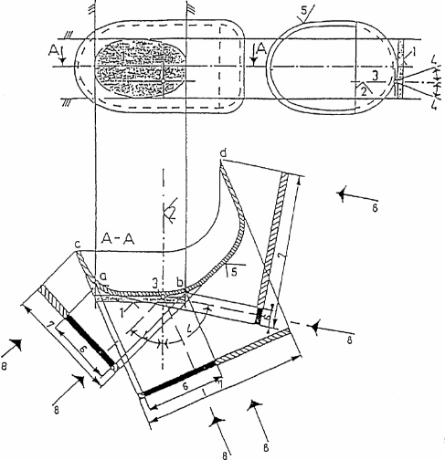
Annex 3 Lamp surfaces, axis and centre of reference, and angles of geometric visibility
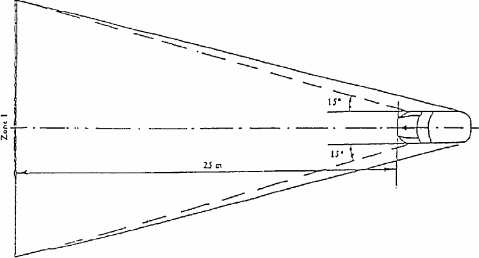
Annex 4 Visibility of a red lamp to the front and visibility of a white lamp to the rear
Annex 5 States of loading to be taken into consideration in determining variations in the vertical orientation of the dipped-beam headlamps
Annex 6 Measurement of the variation of dipped-beam inclination as a function of load
Annex 7 Indication of the stated initial adjustment referred to in paragraph 6.2.6.1 of this Regulation
Annex 8 The controls for the headlamp-leveling devices referred to in paragraph 6.2.6.2.2 of this Regulation
Annex 9 Control of conformity of production
Regulation No. 48
UNIFORM PROVISIONS CONCERNING THE APPROVAL OF VEHICLES WITH REGARD TO THE INSTALLATION OF LIGHTING AND LIGHT-SIGNALLING DEVICES
1. SCOPE
This Regulation applies to the approval of power-driven vehicles intended for use on the road, with or without bodywork, with not less than four wheels and a maximum design speed exceeding 25km/h, and of their trailers, with the exception of vehicles which run on rails, agricultural or forestry tractors and machinery, and public works vehicles.
2. DEFINITIONS
For the purposes of this Regulation
2.1. "Approval of a vehicle" means the approval of a vehicle type with regard to the number and mode of installation of the lighting and light-signalling devices;
2.2. "Vehicle type with regard to the installation of lighting and light-signalling devices" means vehicles which do not differ in the essential respects mentioned in paragraphs 2.2.1 to 2.2.4.
The following are likewise considered not to be "vehicles of a different type": vehicles which differ within the meaning of paragraphs 2.2.1 to 2.2.4., but not in such a way as to entail a change in the kind, number, positioning and geometric visibility of the lamps and the inclination of the dipped-beam prescribed for the vehicle type in question, and vehicles on which optional lamps are fitted or are absent:
2.2.1. The dimension and the external shape of the vehicle;
2.2.2. The number and positioning of the devices;
2.2.3. The headlamp-levelling system;
2.2.4. The suspension system;
2.3. "Transverse plane" means a vertical plane perpendicular to the median longitudinal plane of the vehicle;
2.4. "Unladen vehicle" means a vehicle without driver, crew, passengers and load, but with a full supply of fuel, spare wheel and the tools normally carried;
2.5. "Laden vehicle" means a vehicle loaded to its technically permissible maximum mass, as stated by the manufacturer, who shall also fix the distribution of this mass, between the axles in accordance with the method described in Annex 5;
2.6. "Device" means an element or an assembly of elements used to perform one or more functions;
2.7. "Lamp" means a device designed to illuminate the road or to emit a light signal to other road users. Rear registration plate lamps and retro-reflectors are likewise to be regarded as lamps;
2.7.1. "Light source with regard to filament lamps" means the filament itself. In the case of a lamp having several filaments, each one shall constitute a light source;
2.7.2. "Equivalent lamps" means lamps having the same function and authorized in the country in which the vehicle is registered; such lamps may have different characteristics from those installed on the vehicle when it is approved on condition that they satisfy the requirements of this Regulation;
2.7.3. "Independent lamps" means devices having separate illuminating surfaces, separate light sources and separate lamp bodies;
2.7.4. "Grouped lamps" means devices having separate illuminating surfaces1/ and separate light sources, but a common lamp body;
2.7.5. "Combined lamps" means devices having separate illuminating surfaces1/, but a common light source and a common lamp body;
2.7.6. "Reciprocally incorporated lamps" means devices having separate light sources or a single light source operating under different conditions (for example, optical, mechanical, electrical differences), totally or partially common illuminating surfaces1/ and a common lamp body;
2.7.7. "Single-function lamp" means a part of a device which performs a single lighting or light-signalling function;
2.7.8. "Concealable lamp" means a lamp capable of being partly or completely hidden when not in use. This result may be achieved by means of a movable cover, by displacement of the lamp or by any other suitable means. The term "retractable" is used more particularly to describe a concealable lamp the displacement of which enables it to be inserted within the bodywork;
"Driving beam (main-beam) headlamp" means the lamp used to illuminate the road over a long distance ahead of the vehicle;
2.7.10. "Passing beam (dipped-beam) headlamp" means the lamp used to illuminate the road ahead of the vehicle without causing undue dazzle or discomfort to oncoming drivers and other road-users;
2.7.11. "Direction-indicator lamp" means the lamp used to indicate to other road-users that the driver intends to change direction to the right or to the left;
A direction-indicator lamp or lamps may also be used according to provisions of Regulation No. "X".
2.7.12. "Stop lamp" means the lamp used to indicate to other road-users to the rear of the vehicle that its driver is applying the service brake;
The stop lamps may be activated by the application of a retarder or a similar device;
2.7.13. "Rear registration plate illuminating device" means the device used to illuminate the space reserved for the rear registration plate; such a device may consist of several optical components;
2.7.14. "Front position lamp" means the lamp used to indicate the presence and the width of the vehicle when viewed from the front;
2.7.15. "Rear position lamp" means the lamp used to indicate the presence and width of the vehicle when viewed from the rear;
2.7.16. "Retro-reflector" means a device used to indicate the presence of a vehicle by the reflection of light emanating from a light source not connected to the vehicle, the observer being situated near the source;
For the purposes of this Regulation the following are not considered as retro-reflectors:
2.7.16.1. retro-reflecting number plates;
2.7.16.2. the retro-reflecting signals mentioned in the ADR (European Agreement concerning the international carriage of dangerous goods by road);
2.7.16.3. other retro-reflecting plates and signals which must be used to comply with national requirements for use as regards certain categories of vehicles or certain methods of operation;
2.7.17. "Hazard warning signal" means the simultaneous operation of all of a vehicle's direction-indicator lamps to show that the vehicle temporarily constitutes a special danger to other road-users;
2.7.18. "Front for lamp" means the lamp used to improve the illumination of the road in case of fog, snowfall, rainstorms or dust-clouds;
2.7.19. "Rear fog lamp" means a lamp used to make the vehicle more easily visible from the rear in dense fog;
2.7.20. "Reversing lamp" means the lamp used to illuminate the road to the rear of the vehicle and to warn other road-users that the vehicle is reversing or about to reverse;
2.7.21. "Parking lamp" means a lamp which is used to draw attention to the presence of a stationary vehicle in a built-up area. In such circumstances it replaces the front and rear position lamps;
2.7.22. "End-outline marker lamp" means a lamp fitted near to the extreme outer edge and as close as possible to the top of the vehicle and intended to clearly indicate the vehicle's overall width. This lamp is intended, for certain vehicles and trailers, to complement the vehicle's front and rear position lamps by drawing particular attention to its bulk;
2.7.23. "Side-marker lamp" means a lamp used to indicate the presence of the vehicle when viewed from the side;
2.7.24. "Daytime running lamp" means a lamp facing in a forward direction used to make the vehicle more easily visible when driving during daytime;
2.8. "Light-emitting surface" of a "lighting device", "light-signalling device" or a retro- reflector means all or part of the exterior surface of the transparent material as declared in the request for approval by the manufacturer of the device on the drawing, see Annex 3;
2.9. "Illuminating surface" (see Annex 3);
2.9.1. "Illuminating surface of a lighting device" (paragraphs 2.7.9., 2.7.10., 2.7.18. and 2.7.20) means the orthogonal projection of the full aperture of the reflector, or in the case of headlamps with an ellipsoidal reflector of the "projection lens", on a transverse plane. If the lighting device has no reflector, the definition of paragraph 2.9.2. shall be applied. If the light emitting surface of the lamp extends over part only of the full aperture of the reflector, then the projection of that part only is taken into account.
In the case of a dipped-beam headlamp, the illuminating surface is limited by the apparent trace of the cut-off on to the lens. If the reflector and lens are adjustable relative to one another, the mean adjustment should be used;
2.9.2. "Illuminating surface of a light-signalling device other than a retro-reflector" (paragraphs 2.7.11. to 2.7.15., 2.7.17., 2.7.19. and 2.7.21. to 2.7.24.) means the orthogonal projection of the lamp in a plane perpendicular to its axis of reference and in contact with the exterior light-emitting surface of the lamp, this projection being bounded by the edges of screens situated in this plane, each allowing only 98 % of the total luminous intensity of the light to persist in the direction of the axis of reference. To determine the lower, upper and lateral limits of the illuminating surface, only screens with horizontal or vertical edges shall be used;
2.9.3. "Illuminating surface of a retro-reflector" (paragraph 2.7.16.) means the orthogonal projection of a retro-reflector in a plane perpendicular to its axis of reference and delimited by planes contiguous to the outermost parts of the retro-reflector's optical system and parallel to that axis. For the purposes of determining the lower, upper and lateral edges of the device, only horizontal and vertical planes shall be considered;
2.10. The "apparent surface" for a defined direction of observation means, at the request of the manufacturer or his duly accredited representative, the orthogonal projection of:
either the boundary of the illuminating surface projected on the exterior surface of the lens (a-b),
or the light-emitting surface (c-d),
in a plane perpendicular to the direction of observation and tangential to the most exterior point of the lens (see Annex 3 to this Regulation);
2.11. "Axis of reference" (or "reference axis") means the characteristic axis of the lamp determined by the manufacturer (of the lamp) for use as the direction of reference (H = 0 degrees , V = 0 degrees ) for angles of field for photometric measurements and for installing the lamp on the vehicle;
2.12. "Centre of reference" means the intersection of the axis of reference with the exterior light-emitting surface; it is specified by the manufacturer of the lamp;
2.13. "Angles of geometric visibility" means the angles which determine the field of the minimum solid angle in which the apparent surface of the lamp must be visible. That field of the solid angle is determined by the segments of the sphere of which the centre coincides with the centre of reference of the lamp and the equator is parallel with the ground. These segments are determined in relation to the axis of reference. The horizontal angles b correspond to the longitude and the vertical angles a to the latitude. There must be no obstacle on the inside of the angles of geometric visibility to the propagation of light from any part of the apparent surface of the lamp observed from infinity.
If measurements are taken closer to the lamp, the direction of observation must be shifted parallel to achieve the same accuracy.
On the inside of the angles of geometric visibility no account is taken of obstacles, if they were already presented when the lamp was type-approved.
If, when the lamp is installed, any part of the apparent surface of the lamp is hidden by any further parts of the vehicle, proof shall be furnished that the part of the lamp not hidden by obstacles still conforms to the photometric values prescribed for the approval of the device as an optical unit (see Annex 3 of this Regulation). Nevertheless, when the vertical angle of geometric visibility below the horizontal may be reduced to 5 degrees (lamp at less than 750mm above the ground) the photometric field of measurements of the installed optical unit may be reduced to 5 degrees below the horizontal.
2.14. "Extreme outer edge", on either side of the vehicle, means the plane parallel to the median longitudinal plane of the vehicle and touching its lateral outer edge, disregarding the projection:
2.14.1. of tyres near their point of contact with the ground, and of connections for tyre-pressure gauges;
2.14.2. of any anti-skid devices mounted on the wheels;
2.14.3. of rear-view mirrors;
2.14.4. of side direction-indicator lamps, end-outline marker lamps, front and rear position lamps, parking lamps, retro-reflectors and side-marker lamps;
2.14.5. of Customs seals affixed to the vehicle, and of devices for securing and protecting such seals.
2.15. "Overall width" means the distance between the two vertical planes defined in paragraph 2.14. above.
2.16. The following shall be deemed to be:
2.16.1. "A single lamp" means a device or part of a device, having one function and one apparent surface in the direction of the reference axis (see paragraph 2.10. of this Regulation) and one or more light sources.
For the purpose of installation on a vehicle, a "single lamp" also means any assembly of two independent or grouped lamps, whether identical or not, having the same function, if they are installed so that the projection of their apparent surfaces in the direction of the reference axis occupies not less than 60 % of the smallest rectangle circumscribing the projections of the said apparent surfaces in the direction of the reference axis.
In such a case, each of these lamps shall, where approval is required, be approved as a type "D" lamp.
This possible combination does not apply to main beam headlamps, dipped beam headlamps and front fog lamps. 2.16.2.
"Two lamps" or "an even number of lamps", means a single light-emitting surface in the shape of a band or strip if such band or strip is placed symmetrically in relation to the median longitudinal plane of the vehicle, extends on both sides to within at least 0.4m of the extreme outer edge of the vehicle, and is not less than 0.8m long; the illumination of such surface shall be provided by not less than two light sources placed as close as possible to its ends; the light-emitting surface may be constituted by a number of juxtaposed elements on condition that the projections of the several individual light- emitting surfaces on a transverse plane occupy not less than 60% of the area of the smallest rectangle circumscribing the projections of the said individual light-emitting surfaces;
2.17. "Distance between two lamps" which face in the same direction means the shortest distance between the two apparent surfaces in the direction of the reference axis. Where the distance between the lamps clearly meets the requirements of the Regulation, the exact edges of apparent surfaces need not be determined;
2.18. "Operating tell-tale" means a visual or auditory signal (or any equivalent signal) indicating that a device has been switched on and is operating correctly or not;
2.19. "Circuit-closed tell-tale" means a visual (or any equivalent signal) indicating that a device has been switched on, but not indicating whether or not it is operating correctly or not;
2.20. "Optional lamp" means a lamp, the installation of which is left to the discretion of the manufacturer;
2.21. "Ground" means the surface on which the vehicle stands which should be substantially horizontal;
2.22. "Movable components" of the vehicle mean those body panels or other vehicle parts the position(s) of which can be changed by tilting, rotating or sliding without the use of tools. They do not include tiltable diver cabs of trucks;
2.23. "Normal position of use of a movable component" means the position(s) of a movable component specified by the vehicle manufacturer for the normal condition of use and the park condition of the vehicle;
2.24. "Normal condition of use of a vehicle" means:
2.24.1. for a motor vehicle, when the vehicle is ready to move with its propulsion engine running and its movable components in the normal position(s) as defined is paragraph 2.23.;
2.24.2. and for a trailer, when the trailer is connected to a drawing motor vehicle in the conditions as prescribed in paragraph 2.24.1. and its movable components are in the normal position(s) as defined in paragraph 2.23.
2.25. "Park condition of a vehicle" means:
2.25.1. for a motor vehicle, when the vehicle is at a standstill and its propulsion engine is not running and its movable components are in the normal position(s) as defined in paragraph 2.23.;
2.25.2. and for a trailer, when the trailer is connected to a drawing motor vehicle in the condition as described in paragraph 2.25.1. and its movable components are in the normal position(s) as defined in paragraph 2.23.
3. APPLICATION FOR APPROVAL
3.1. The application for approval of a vehicle type with regard to the installation of its lighting and light-signalling devices shall be submitted by the vehicle manufacturer or his duly accredited representative.
3.2. It shall be accompanied by the following documents and particulars in triplicate:
3.2.1. a description of the vehicle type with regard to the items mentioned in paragraphs 2.2.1. to 2.2.4. above, together with the restrictions on loading, particularly the maximum permissible load in the boot;
3.2.2. a list of the devices prescribed by the manufacturer for the lighting and light-signalling assembly. The list may include several types of device for each operation. Each type must be duly identified (component, type-approval mark, name of manufacturer, etc.); in addition the list may include in respect of each function the additional annotation "or equivalent devices";
3.2.3. a layout drawing of the lighting and light-signalling equipment as a whole, showing the position of the various devices on the vehicle; and
3.2.4. if necessary, in order to verify the conformity to the prescriptions of the present Regulation, layout drawing(s) for each individual lamp showing the illuminating surface as defined in paragraph 2.9., the light-emitting surface as defined in paragraph 2.8., the axis of reference as defined in paragraph 2.11. and the centre of reference as defined in paragraph 2.12. This information is not necessary in the case of the rear registration plate lamp (see paragraph 2.7.13.).
3.2.5. The application shall include a statement of the method used for the definition of the apparent surface (see paragraph 2.10.).
3.3. An unladen vehicle fitted with a complete set of lighting and light-signalling equipment, as prescribed in paragraph 3.2.2. above, and representative of the vehicle type to be approved shall be submitted to the technical service responsible for conducting approval tests.
3.4. The document provided in Annex 1 of this Regulation shall be attached to the type- approval documentation.
4. APPROVAL
4.1. If the vehicle type submitted for approval pursuant to this Regulation meets the requirements of the Regulation in respect of all the devices specified in the list, approval of that vehicle type shall be granted.
4.2. An approval number shall be assigned to each type approved. Its first two digits (at present 02, corresponding to the 02 series of amendments) shall indicate the series of amendments incorporating the most recent major technical amendments made to the Regulation at the time of issue of the approval. The same Contracting Party shall not assign this number to another vehicle type or to the same vehicle type submitted with equipment not specified in the list referred to in paragraph 3.2.2. above, subject to the provisions of paragraph 7 of this Regulation.
4.3. Notice of approval or of extension or refusal of approval or production definitely discontinued of a vehicle type/part pursuant to this Regulation shall be communicated to the Parties to the 1958 Agreement applying this Regulation, by means of a form conforming to the model in Annex 1 to this Regulation.
4.4. There shall be affixed, conspicuously and in a readily accessible place specified on the approval form, to every vehicle conforming to a vehicle type approved under this Regulation, an international approval mark consisting of:
4.4.1. A circle surrounding the letter "E" followed by the distinguishing number of the country which has granted approval;
4.4.2. The number of this Regulation, followed by the letter "R", a dash and the approval number to the right of the circle prescribed in paragraph 4.4.1.
4.5. If the vehicle conforms to a vehicle type approved, under one or more other Regulations annexed to the Agreement, in the country which has granted approval under this Regulation, the symbol prescribed in paragraph 4.4.1. need not to be repeated; in such a case the Regulation and approval numbers and the additional symbols of all the Regulations under which approval has been granted in the country which has granted approval under this Regulation shall be placed in vertical columns to the right of the symbol prescribed in paragraph 4.4.1.
4.6. The approval mark shall be clearly legible and be indelible.
4.7. The approval mark shall be placed close to or on the vehicle data plate affixed by the manufacturer.
4.8. Annex 2 to this Regulation gives examples of arrangements of approval marks.
5. GENERAL SPECIFICATIONS
5.1. The lighting and light-signalling devices shall be so fitted that under normal conditions of use as defined in paragraphs 2.24., 2.24.1. and 2.24.2. and notwithstanding any vibrations to which they may be subjected, they retain the characteristics prescribed by this Regulation and enable the vehicle to comply with the requirements of this Regulation. In particular, it shall not be possible for the lamps to be inadvertently maladjusted.
5.2. The illuminating lamps described in paragraphs 2.7.9., 2.7.10. and 2.7.18. shall be so installed that correct adjustment of their orientation can easily be carried out.
5.3. For all light-signalling devices, including those mounted on the side panels, the reference axis of the lamp when fitted to the vehicle must be parallel to the bearing plane of the vehicle on the road; in addition it must be perpendicular to the median longitudinal plane of the vehicle in the case of side retro-reflectors and of side-marker lamps and parallel to that plane in the case of all other signalling devices. In each direction tolerance of +/-3 degrees shall be allowed. In addition, any specific instructions as regards fitting laid down by the manufacturer must be complied with.
5.4. In the absence of specific instructions, the height and orientation of the lamps shall be verified with the vehicle unladen and placed on a flat, horizontal surface in the condition defined in paragraphs 2.24., 2.24.1. and 2.24.2.
5.5. In the absence of specific instructions lamps constituting a pair shall:
5.5.1. be fitted to the vehicle symmetrically in relation to the median longitudinal plane (this estimate to be based on the exterior geometrical form of the lamp and not on the edge of its illuminating surface referred to in paragraph 2.9.);
5.5.2. be symmetrical to one another in relation to the median longitudinal plane; this requirement is not valid with regard to the interior structure of the lamp;
5.5.3. satisfy the same colorimeric requirements; and
5.5.4. have substantially identical photometric characteristics.
5.6. On vehicles whose external shape is asymmetrical the above requirements shall be satisfied so far as is possible.
5.7. Lamps may be grouped, combined or reciprocally incorporated with one another provided that all requirements regarding colour, position, orientation, geometric visibility, electrical connections and other requirements, if any, for each lamp, are fulfilled.
5.8. The maximum height above the ground shall be measured from the highest point and the minimum height from the lowest point of the apparent surface in the direction of the reference axis.
In the case of dipped-beam headlamp, the minimum height in relation to the ground is measured from the lowest point of the effective outlet of the optical system (e.g. reflector, lens, projection lens) independent of its utilization.
Where the (maximum and minimum) height above the ground clearly meets the requirements of the Regulation, the exact edges of any surface need not be determined. The position, as regards width, will be determined from that edge of the apparent surface in the direction of the reference axis which is the furthest from the median longitudinal plane of the vehicle when referred to the overall width, and from the inner edges of the apparent surface in the direction of the reference axis when referred to the distance between lamps.
Where the position, as regards width, clearly meets the requirements of the Regulation, the exact edges of any surface need not be determined.
5.9. In the absence of specific instructions, no lamps other than direction-indicator lamps, the vehicle-hazard warning signal and amber side marker lamps complying with paragraph 6.18.7. below, shall be flashing lamps.
5.10. No red light which could give rise to confusion shall be emitted from a lamp as defined in paragraph 2.7. in a forward direction and no white light which could give rise to confusion, other than from the reversing lamp, shall be emitted from a lamp as defined in paragraph 2.7. in a rearward direction. No account shall be taken of lighting devices fitted for the interior lighting of the vehicle. In case of doubt, this requirement shall be verified as follows:
5.10.1. For the visibility of red light towards the front, there must be no direct visibility of the light-emitting surface of a red lamp if viewed by an observer moving within Zone 1 in a transverse plane situated 25m in front of the vehicle (see Annex 4);
5.10.2. For the visibility of white light towards the rear, there must be no direct visibility of a light-emitting surface of a white lamp if viewed by an observer moving within Zone 2 in a transverse plane situated 25m behind the vehicle (see Annex 4);
5.10.3. In their respective planes, the zones 1 and 2 explored by the eye of the observer are bounded:
5.10.3.1. in height, by two horizontal planes 1m and 2.2m respectively above the ground;
5.10.3.2. in width, by two vertical planes which, forming to the front and to the rear respectively and angle of 15 degrees outwards from the vehicle's median longitudinal plane, pass through the point or points of contact of vertical planes parallel to the vehicle's median longitudinal plane delimiting the vehicle's over all width; if there are several points of contact, the foremost shall correspond to the forward plane and the rearmost to the rearward plane.
5.11. The electrical connections must be such that the front and rear position lamps, the end- outline marker lamps, if they exist, the side-marker lamps, if they exist, and the rear registration plate lamp can only be switched on and off simultaneously. This condition does not apply when using front and rear position lamps, as well as side-marker lamps when combined or reciprocally incorporated with said lamps, as parking lamps and when side-marker lamps are permitted to flash.
5.12. The electrical connections must be such that the main-beam and dipped-beam headlamps and the front fog lamps cannot be switched on unless the lamps referred to in paragraph 5.11. are also switched on. This requirement shall not apply, however, to main-beam or dipped-beam headlamps when their luminous warnings consist of the intermittent lighting up at short intervals of the main-beam headlamp or the intermittent lighting up at short intervals of the dipped-beam headlamp or the alternate lighting up at short intervals of the main-beam and dipped-beam headlamps.
5.13. Tell-tale
Where a "circuit-closed" tell-tale is prescribed by this Regulation it may be replaced by an "operating" tell-tale.
5.14. Concealable lamps
5.14.1. The concealment of lamps shall be prohibited, with the exception of the main-beam headlamps, the dipped-beam headlamps and the front fog lamps, which may be concealed when they are not in use.
5.14.2. In the event of any failure affecting the operation of the concealment device(s) the lamps shall remain in the position of use, if already in use, or shall be capable of being moved into the position of use without the aid of tools.
5.14.3. It must be possible to move the lamps into the position of use and to switch them on by means of a single control, without excluding the possibility of moving them into the position of use without switching them on. However, in the case of grouped main-beam and dipped-beam headlamps, the control referred to above is required only to activate the dipped-beam headlamps.
5.14.4. It must not be possible deliberately, from the driver's seat, to stop the movement of switched-on lamps before they reach the position of use. If there is a danger of dazzling other road users by the movement of the lamps, they may light up only when they have reached their position of use.
5.14.5. When the concealment device has a temperature of -30 degrees C to +50 degrees C the headlamps must be capable of reaching the position of use within three seconds of initial operation of the control.
5.15. The colours of the light emitted by the lamps are the following: main-beam headlamp: white
dipped-beam headlamp: white
front fog lamp: white or yellow
reversing lamp: white
direction-indicator lamp: amber
hazard warning signal: amber
stop lamp: red
rear registration plate lamp: white
front position lamp: white
rear position lamp: red
rear fog lamp: red
parking lamp: white in front, red at the rear, amber if reciprocally incorporated in the side direction-indicator lamps or in the side-marker lamps.
side-marker lamp: amber; however the rearmost side-marker lamp can be red if it is grouped or combined or reciprocally incorporated with the rear position lamp, the rear end-outline marker lamp, the rear fog lamp, the stop lamp or is grouped or has part of the light emitting surface in common with the rear retro-reflector.
end-outline marker lamp: white in front, red at the rear
daytime running lamp: white
rear retro-reflector, triangular: red
rear retro-reflector, triangular: red
front retro-reflector, triangular: identical to incident light
side retro-reflector, triangular: amber; however the rearmost side retro-reflector can be red if it is grouped or has part of the light emitting surface in common with the rear position lamp, the rear end-outline marker lamp, the rear fog lamp, the stop-lamp or the red rearmost side-marker lamp.
5.16. Number of lamps
The number of lamps mounted on the vehicle shall be equal to the number(s) specified in subparagraph 2 of each of the paragraphs 6.1. to 6.19.
5.17. Except as provided by paragraphs 5.18., 5.19. and 5.21., lamps may be installed on movable components.
5.18. Rear position lamps, rear direction-indicators and rear retro-reflectors, triangular as well as non triangular, must not be installed on movable components unless at all fixed positions of the movable components the lamps on the movable components meet all the position, geometric visibility and photometric requirements for those lamps.
Should the above functions be obtained by an assembly of two lamps marked "D" (see paragraph 2.16.1.) only one of these lamps needs to meet the above mentioned requirements.
5.19. There must not be any movable component, with or without a light-signalling device installed on it, which in any fixed position hides more than 50% of the apparent surface of front and rear position lamps, front and rear direction-indicator lamps and retro- reflectors when viewed in the reference axis of this specific device.
If this is not practicable:
5.19.1. A remark in the communication form (item 10.1. of Annex 1) shall inform other Administrations that more than 50% of the apparent surface in the direction of the reference axis can be hidden by the movable components;
5.19.2. In case of paragraph 5.19.1. a notice in the vehicle shall inform the user that in certain position(s) of the movable components other road users shall be warned of the presence of the vehicle on the road; for example by means of a warning triangle or other devices according to national requirements for use on the road.
5.20. When the movable components are in a position other than a "Normal position" as defined in paragraph 2.23. the devices installed on them shall not cause undue discomfort to road users.
5.21. When a lamp is installed on a movable component and the movable component is in the normal position(s) of use (see paragraph 2.23.), the lamp must always return to the position(s) specified by the manufacturer in accordance with this Regulation. In the case of dipped-beam headlamps and front fog lamps, this requirement shall be considered satisfied if, when the movable components are moved and returned to the normal position 10 times, no value of the angular inclination of these lamps, relative to its support, measured after each operation of the movable component, differs by more than 0.15% from the average of the 10 measured values.
If this value is exceeded, each limit specified in paragraph 6.2.6.1.1. shall then be modified by this excess to decrease the allowed range of inclinations when checking the vehicle according to Annex 6.
5.22. With the exception of retro-reflectors, a lamp even bearing an approval mark is deemed not to be present when it cannot be made to operate by the sole installation of a filament lamp.
5.23. Any temporary fail-safe replacement of the light-signalling function of a rear position lamp is allowed, provided that the substituting function in case of a failure is similar in colour, main intensity and position to the function that has ceased to operate and provided that the substituting device remains operational in its original safety function. During substitution, a tell-tale on the dashboard (see para. 2.18. of this Regulation) shall indicate occurrence of a temporary replacement and need for repair.
6. INDIVIDUAL SPECIFICATIONS
6.1. MAIN-BEAM HEADLAMP
6.1.1. Presence
Mandatory on motor vehicles. Prohibited on trailers.
6.1.2. Number
Two or four.
Where a vehicle is fitted with four concelable headlamps the installation of two additional headlamps shall only be authorized for the purpose of light-signalling, consisting of intermittent illumination, at short intervals (see paragraph 5.12.) in daylight.
6.1.3. Arrangement
No individual specifications.
6.1.4. Position
6.1.4.1. In width: no individual specifications.
6.1.4.2. In height: no individual specifications.
6.1.4.3. In length: at the front of the vehicle and fitted in such a way that the light emitted does not cause discomfort to the driver either directly or indirectly through the rear-view mirrors and/or other reflecting surfaces of the vehicle.
6.1.5. Geometric visibility
The visibility of the illuminating surface, including its visibility in areas which do not appear to be illuminated in the direction of observation considered, must be ensured within a divergent space defined by generating lines based on the perimeter of the illuminating surface and forming an angle of not less than 5 degrees with the axis of reference of the headlamp. The origin of the angles of geometric visibility is the perimeter of the projection of the illuminating surface on a transverse plane tangent to the foremost part of the lens of the headlamp.
6.1.6. Orientation
Towards the front.
Apart from the devices necessary to maintain correct adjustment, and when there are two pairs of headlamps one pair, consisting of headlamps functioning as main-beam headlamps only, may swivel, according to the angle of lock of the steering, about a substantial vertical axis.
6.1.7. Electrical connections
6.1.7.1. The main-beam headlamps may be switched on either simultaneously or in pairs. For changing over from the dipped to the main beam at least one pair of main-beam headlamps shall be switched on. For changing over from the main-beam to the dipped- beam all main-beam headlamps shall be switched off simultaneously.
6.1.7.2. The dipped-beams may remain switched on at the same time as the main-beams.
6.1.7.3. Where four concealable headlamps are fitted their raised position must prevent the simultaneous operation of any additional headlamps fitted, if these are intended to provide light signals consisting of intermittent illumination at short intervals (see paragraph 5.12.) in daylight.
6.1.8. Tell-tale
Circuit-closed tell-tale mandatory.
6.1.9. Other requirements
6.1.9.1. The aggregate maximum intensity of the main-beam headlamps which can be switched on simultaneously shall not exceed 225,000cd, which corresponds to a reference value of 75.
6.1.9.2. This maximum intensity shall be obtained by adding together the individual reference marks which are indicated on the several headlamps. The reference mark "10" shall be given to each of the headlamps marked "R" or "CR".
6.2. DIPPED-BEAM HEADLAMP
6.2.1. Presence
Mandatory on motor vehicles. Prohibited on trailers.
6.2.2. Number
Two.
6.2.3. Arrangement
No special requirement.
6.2.4. Position
6.2.4.1. In width: the edge of the apparent surface in the direction of the reference axis which is farthest from the vehicle's median longitudinal plane shall be not more than 400mm from the extreme outer edge of the vehicle. The inner edges of the apparent surfaces in the direction of the reference axes shall be not less than 600mm apart. This does not apply however, for M1 category vehicles; for all other categories of motor vehicles this distance may be reduced to 400mm where the overall width of the vehicle is less than 1,300mm.
6.2.4.2. In height: not less than 500mm and not more than 1,200mm above the ground. For category N3G (off-road) vehicles*/, the maximum height may be increased to 1,500mm.
6.2.4.3. In length: at the front of the vehicle. This requirement shall be deemed to be satisfied if the light emitted does not cause discomfort to the driver either directly, or indirectly through the rear-view mirrors and/or other reflecting surfaces of the vehicle.
6.2.5. Geometric visibility
Defined by angles alpha and beta specified in paragraph 2.13.:
alpha =15 degrees upwards and 10 degrees downwards,
beta = 45 degrees outwards and 10 degrees inwards.
Since the photometric values required for dipped-beam headlamps do not cover the full geometric field of vision, a minimum value of 1cd in the space remaining is required for type-approval purposes. The presence of partitions or other items of equipment near the headlamp shall not give rise to secondary effects causing discomfort to other road users.
6.2.6. Orientation
Towards the front.
6.2.6.1. Vertical orientation
6.2.6.1.1. The initial downward inclination of the cut-off of the dipped-beam to be set in the unladen vehicle state with one person in the drivers's seat shall be specified within an accuracy of 0.1% by the manufacturer and indicated in a clearly legible and indelible manner on each vehicle close to either headlamp or the manufacturer's plate by the symbol shown in annex 7.
The value of this indicated downward inclination shall be defined in accordance with paragraph 6.2.6.1.2.
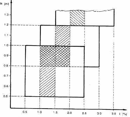
6.2.6.1.2. Depending on the mounting height in metres (h) of the lower edge of the apparent surface in the direction of the reference axis of the dipped-beam headlamp, measured on the unladen vehicles, the vertical inclination of the cut-off of the dipped beam shall, under all the static conditions of Annex 5, remain between the following limits and the initial aiming shall have the following values. For category N3G (off-road) vehicles where the headlamps exceed a height of 1,200mm, the limits for the vertical inclination of the cut-off shall be between:
-1.5% and -3.5%. The initial aim shall be set between : -2% and -2.5%:
h < 0.8
limits:between -0.5% and -2.5%
initial aiming:between -1.0% and -1.5%
0.8<h<1.0
limits:between -0.5% and -2.5%
initial aiming:between -1.0% and -1.5%
or, at the discretion of the manufacturer,
limits:between -1.0% and -3.0%
initial aiming:between -1.5% and -2.0%
The application for the vehicle type approval shall, in this case, contain information as to which of the two alternatives is to be used.
h > 1.0
limits:between -1.0% and -3.0%
initial aiming:between -1.5% and -2.0%
The above limits and the initial aiming values are summarized in the diagram below:
6.2.6.2. Headlamp levelling device
6.2.6.2.1. In the case where a headlamp levelling device is necessary to satisfy the requirements of paragraphs 6.2.6.1.1. and 6.2.6.1.2., the device shall be automatic.
6.2.6.2.2. However, devices which are adjusted manually, either continuously or non- continuously, shall be permitted, provided they have a stop positon at which the lamps can be returned to the initial inclination defined in paragraph 6.2.6.1.1. by means of the usual adjusting screws or similar means.
These manually adjustable devices must be operable from the driver's seat.
Continually adjustable devices must have reference makes indicating the loading conditions that require adjustment of the dipped-beam.
The number of positions on devices which are not continuously adjustable must be such as to ensure compliance with the range of values prescribed in paragraph 6.2.6.1.2. in all the loading conditions defined in Annex 5.
For these devices also, the loading conditions of Annex 5 that require adjustment of the dipped-beam shall be clearly marked near the control of the device (see Annex 8).
6.2.6.2.3. In the event of a failure of devices described in paragraphs 6.2.6.2.1. and 6.2.6.2.2., the dipped-beam shall not assume a position in which the dip is less than it was at the time when the failure of the device occurred.
6.2.6.3. Measuring procedure
6.2.6.3.1. After adjustment of the initial inclination, the vertical inclination of the dipped-beam, expressed in percent, shall be measured in static conditions under all the loading conditions defined in Annex 5.
6.2.6.3.2. The measurement of the variation of dipped-beam inclination as a function of load must be carried out in accordance with the test procedure set out in Annex 6.
6.2.7. Electrical connections
The control for changing over to the dipped beam must switch off all main-beam headlamps simultaneously.
The dipped beams may remain switched on at the same time as the main beams. In the case of dipped-beam headlamps according to Regulation No. "X" the gas- discharge light sources shall remain switched on during the main-beam operation.
6.2.8. Tell-tale
Tell-tale optional.
6.2.9. Other requirements
The requirements of paragraph 5.5.2. shall not apply to dipped-beam headlamps. Dipped-beam headlamps shall not swivel according to the angle of lock of steering. Dipped-beam headlamps with gas-discharge light sources shall only be permitted in conjunction with the installation of headlamp cleaning device(s) according to Regulation No. 45. In addition, with respect to vertical inclination, the provision of paragraph 6.2.6.2.2. shall not be applied when these headlamps are installed.
6.3. FRONT FOG LAMP
6.3.1. Presence
Optional on motor vehicles. Prohibited on trailers.
6.3.2. Number
Two.
6.3.3. Arrangement
No special requirement.
6.3.4. Position
6.3.4.1. In width: that point on the apparent surface in the direction of the reference axis which is farthest from the vehicle's median longitudinal plane shall not be more than 400mm from the extreme outer edge of the vehicle.
6.3.4.2. In height:
Minimum: Not less than 250mm above the ground.
Maximum: For M1 category vehicles not more than 800mm above the ground; For all other categories of vehicles no maximum height. However, no point on the apparent surface in the direction of the reference axis must be higher than the highest point on the apparent surface in the direction of the reference axis of the dipped-beam headlamp.
6.3.4.3. In length: at the front of the vehicle. This requirement shall be deemed to be satisfied if the light emitted does not cause discomfort to the driver either directly, or indirectly through the rear-view mirrors and/or other reflecting surfaces of the vehicle.
6.3.5. Geometric visibility
Defined by angles alpha and beta specified in paragraph 2.13.,
alpha = 5 degrees upwards and downwards,
Beta = 45 degrees outwards and 10 degrees inwards.
6.3.6. Orientation
Towards the front.
The alignment of the front fog lamps must not vary according to the angle of lock of the steering.
They must be directed forward without causing undue dazzling or discomfort to oncoming drives and other road users.
6.3.7. Electrical connections
It must be possible to switch the front fog lamps on and off independently of the main- beam headlamps, the dipped-beam headlamps or any combination of main- and dipped- beam headlamps.
6.3.8. Tell-tale
Circuit-closed tell-tale mandatory. An independent non-flashing warning light.
6.3.9. Other requirements
None.
6.4. REVERSING LAMP
6.4.1. Presence
Mandatory on motor vehicles. Optional on trailers.
6.4.2. Number
One or two on all vehicles.
Optional: Additional one or two white fog lamps approved to Regulation No.19 on vehicles of category N2, N3, M2, M3, O2, O3 and O4.
6.4.3. Arrangement
No special requirement.
6.4.4. Position
6.4.4.1. In width: no special requirement.
6.4.4.2. In height: For M1 category vehicles no special requirement. For all other categories of vehicles not less than 250mm nor more than 1200mm above the ground
6.4.4.3. In length: at the back of the vehicle.
6.4.5. Geometric visibility
Defined by angles alpha and beta specified in paragraph 2.13.,
alpha= 15 degrees upwards and 5 degrees downwards,
beta= 45 degrees to right and to left if there is only one light, 45 degrees outwards and 30 degrees inwards if there are two. In case of fog lamps approved to Reguration No.19:
alpha= 5 degrees upwards and downwards,
beta= 45 degrees outwards and inwards if there is only one lamp, 45 degrees outwards and 10 degrees inwards if there are two lamps.
6.4.6. Orientation
Rearwards.
6.4.7. Electrical connection
6.4.7.1. They shall be such that the lamp can light up only if the reverse gear is engaged and if the device which controls the starting and stopping of the engine is in such a position that operation of the engine is possible. It shall not light up or remain lit if either of the above conditions is not satisfied.
6.4.7.2. When fog lamps approved to Regulation No.19 are mounted they shall be switched on and off separately while at the same time the conditions of paragraph 6.4.7.1. remain satisfied. When one of the conditions of paragraph 6.4.7.1. is no longer satisfied, the lamp(s) shall be switched off, and remain off unitil the conditions of paragraph 6.4.7.1. are fulfilled and the lamp(s) are deliberately switched on again.
6.4.8. Tell-tale
Tell-tale optional.
6.4.9. Other requirements
None.
6.5. DIRECTION-INDICATOR LAMP
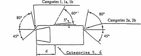
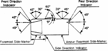
6.5.1. Presence (see figure below)
Mandatory. Types of direction-indicator lamps fall into categories (1, 1a, 1b, 2a, 2b, 5
and 6) the assembly of which on one vehicle constitutes an arrangement ("A" and "B"). Arrangement "A" shall apply to all motor vehicles.
Arrangement "B" shall apply to trailers only.
6.5.2. Number
According to the arrangement.
6.5.3. Arrangements (see figure below)
A: two front direction-indicator lamps of the following categories:
1 or 1a or 1b,
if the distance between the edge of the apparent surface in the direction of the reference axis of this lamp and that of the apparent surface in the direction of the reference axis of the dipped-beam headlamp and/or the front fog lamp, if there is one, is at least 40mm; 1a or 1b,
if the distance between the edge of the apparent surface in the direction of the reference axis of this lamp and that of the apparent surface in the direction of the reference axis of the dipped-beam headlamp and/or the front fog lamp, if there is one, is greater than 20mm and less than 40mm;
1b,
if the distance between the edge of the apparent surface in the direction of the reference axis of this lamp and that of the apparent surface in the direction of the reference axis of the dipped-beam headlamp and/or the front fog lamp, if there is one, is less than or equal to 20mm;
two rear direction-indicator lamps (categories 2a or 2b);
two side direction-indicator lamps of categories 5 or 6 (minimum requirements);
5
for all M1 vehicles;
for N1, M2 and M3 vehicles not exceeding 6m in length.
6
for all N2 and N3 vehicles;
for N1, M2 and M3 vehicles exceeding 6m in length.
It is permitted to replace category 5 side direction-indicator lamps by category 6 side direction-indicator lamps in all instances.
Where lamps combining the functions of front direction-indicator lamps (categories 1, 1a, 1b) and side direction-indicator lamps (categories 5 or 6) are fitted, two additional side direction-indicator lamps (categories 5 or 6) may be fitted to meet the visibility requirements of paragraph 6.5.5.
B: two rear direction-indicator lamps (categories 2a or 2b).
6.5.4. Position
6.5.4.1. In width: the edge of the apparent surface in the direction of the reference axis farthest from the median longitudinal plane of the vehicle must no be more than 400mm from the extreme outer edge of the vehicle.
The distance between the inner edges of the two apparent surfaces in he direction of the reference axis shall not be less than 600mm.
This distance may be reduced to 400mm where the overall width of the vehicle is less than 1,300mm.
6.5.4.2. In height: above the ground.
6.5.4.2.1. The height of the light-emitting surface of the side direction-indicator lamps of categories 5 or 6 must not be:
less than 350mm for M1 category of vehicles, and 500mm for all other categories of vehicles, both measured from the lowest point; and more than:1,500mm measured from the highest point.
6.5.4.2.2. The height of the direction-indicator lamps of categories 1, 1a, 1b, 2a and 2b, measured in accordance with paragraph 5.8., shall not be less than 350mm or more than 1,500mm.
6.5.4.2.3. If the structure of the vehicle does not permit these upper limits, measured as specified above, to be respected, they may be increased to 2,300mm for side direction-indicator lamps of categories 5 and 6, and to 2,100mm for the direction-indicator lamps of categories 1, 1a, 1b, 2a and 2b.
6.5.4.3. In length (see figure below)
The distance between the light-emitting surface of the side direction-indicator lamp (categories 5 and 6) and the transverse plane which marks the forward boundary of the vehicle's overall length, shall not exceed 1,800mm. However for M1 category vehicles, and for all other categories of vehicles if the structure of the vehicle makes it impossible to comply with the minimum angles of visibility, this distance may be increased to 2,500mm.
6.5.5. Geometric visibility
6.5.5.1 Horizontal angles, see figure below.
Vertical angles: 15 degrees above and below the horizontal for direction-indicator lamps of categories 1, 1a, 1b, 2a, 2b and 5. The vertical angle below the horizontal may be reduced to 5 degrees if the lamps are less than 750mm above the ground; 30 degrees above and 5 degrees below the horizontal for direction-indicator lamps of category 6.
Figure (see paragraph 6.5)
Arrangement A

Arrangement B
6.5.5.2 or, at the discretion of the manufacturer, for M1 category vehicles : Front and rear direction indicator lamps, as well as side-marker lamps Horizontal angles see figure below:
6.5.6. Orientation
According to the specifications for installation by the manufacturer, if any.
6.5.7. Electrical connections
Direction-indicator lamps shall switch on independently of the other lamps. All direction-indicator lamps on one side of a vehicle shall be switched on and off by means of one control and shall flash in phase. On M1 and N1 vehicles less than 6m in length, with an arrangement complying with paragraph 6.5.5.2 above, the amber side-marker lamps, when mounted, shall also flash at the same frequency (in Phase) with the direction indicator lamps.
6.5.8. Tell-tale
Operating tell-tale mandatory for front and rear direction-indicator lamps. It may be visual or auditory or both. If it is visual it shall be a flashing light which, at least in the event of the malfunction of any of the front or rear direction-indicator lamps, is either extinguished, or remains alight without flashing, or shows a marked change of frequency. If it is entirely auditory it shall be clearly audible and shall show a marked change of frequency, at least in the event of the malfunction of any of the front or rear direction-indicator lamps.
If a motor vehicle is equipped to draw a trailer, it must be fitted with a special visual operational tell-tale for the direction-indicator lamps on the trailer unless the tell-tale of the drawing vehicle allows the failure of any one of the direction-indicator lamps on the vehicle combination thus formed to be detected.
6.5.9. Other requirements
The light shall be a flashing light flashing 90 +/- 30 times per minute.
Operation of the light-signal control shall be followed within not more than one second by the emission of light and within not more than one and one-half seconds by its first extinction. If a motor vehicle is equipped to draw a trailer, the control of the direction- indicator lamps on the drawing vehicle shall also operate the indicator lamps of the trailer. In the event of failure, other than a short-circuit, of one direction-indicator lamp, the others must continue to flash, but the frequency in this condition may be different from that prescribed.
6.6. HAZARD WARNING SIGNAL
6.6.1. Presence
Mandatory.
The signal shall be given by simultaneous operation of the direction-indicator lamps in accordance with the requirements of paragraph 6.5. above.
6.6.2. Number
As specified in paragraph 6.5.2.
6.6.3. Arrangement
As specified in paragraph 6.5.3.
6.6.4. Position
6.6.4.1. Width
As specified in paragraph 6.5.4.1.
6.6.4.2. Height
As specified in paragraph 6.5.4.2.
6.6.4.3. Length
As specified in paragraph 6.5.4.3.
6.6.5. Geometric visibility
As specified in paragraph 6.5.5.
6.6.6. Orientation
As specified in paragraph 6.5.6.
6.6.7. Electrical connections
The signal shall be operated by means of a separate control enabling all the direction- indicator lamps to flash in phase. On M1 and N1 vehicles less than 6m in length, with an arrangement complying with paragraph 6.5.5.2 above, the amber side-marker lamps, when mounted, shall also flash at the same frequency (in Phase) with the direction indicator lamps.
6.6.8. Tell-tale
Circuit-closed tell-tale mandatory. Flashing warning light, which can operate in conjunction with the tell-tale(s) specified in paragraph 6.5.8.
6.6.9. Other requirements
As specified in paragraph 6.5.9.. If a power-driven vehicle is equipped to draw a trailer the hazard warning signal control shall also be capable of bringing the direction- indicator lamps on the trailer into action. The hazard warning signal shall be able to function even if the device which starts or stops the engine is in a position which makes it impossible to start the engine.
6.7. STOP LAMP
6.7.1. Presence
Devices of S1 or S2 categories:
mandatory on all categories of vehicles.
Devices of S3 category:
mandatory on M1 category of vehicles; optional on other categories of vehicles.
6.7.2. Number
Two devices of S1 or S2 categories and one of S3 category on all categories of vehicles. Only when the median longitudinal plane of the vehicle is not located on a fixed body panel but separates one or two movable parts of the vehicle (e.g. doors), and lacks sufficient space to install a single device of the S3 category on the median longitudinal plane above such movable parts, either: two devices of the S3 category type "D" may be installed, or one device of the S3 category may be installed offset to the left or to the right of the median longitudinal plane.
6.7.3. Arrangement
No special requirement.
6.7.4. Position
6.7.4.1. In width:
For M1 category vehicles: For S1 or S2 categories devices that point on the apparent surface in the direction of the reference axis which is farthest from the vehicle's median longitudinal plane shall not be more than 400mm from the extreme outer edge of the vehicle; for the distance in between the inner edges of the apparent surfaces in the direction of the reference axes there is no special requirement.
For all other categories of vehicles: For S1 or S2 categories devices the distance in between the inner edges of the apparent surfaces in the direction of the reference axes shall be not less than 600mm apart. This distance may be reduced to 400mm if the overall width of the vehicle is less than 1,300mm.
For S3 category devices: the centre of reference
6.7.4.2. In height:
For S1 or S2 categories devices: above the ground, not less than 350mm nor more than 1,500mm (2,100mm if the shape of the bodywork makes it impossible to keep within 1,500mm).
For S3 category devices, the horizontal plane tangential to the lower edge of the apparent surface shall:
either not be more than 150mm below the horizontal plane tangential to the lower edge of the exposed surface of the glass or glazing of the rear window, or
not be less than 850mm above the ground.
However, the horizontal plane tangential to the lower edge of the apparent surface of S3 category device shall be above the horizontal plane tangential to the upper edge of the apparent surface of S1 or S2 categories devices.
6.7.4.3. In length:
For S1 or S2 categories devices: at the rear of the vehicle. For S3 category devices: no special requirement.
6.7.5. Geometric visibility
Horizontal angle:For S1 or S2 categories devices: 45 degrees to the left and to the right of the longitudinal axis of the vehicle;
For S3 category devices: 10 degrees to the left and to the right of the longitudinal axis of the vehicle;
Vertical angle:For S1 or S2 categories devices: 15 degrees above and below the horizontal. However, the vertical angle below the horizontal may be reduced to 5 degrees , if the height of the lamp is less than 750mm;
For S3 category devices: 10 degrees above and 5 degrees below the horizontal.
6.7.6. Orientation
Towards the rear of the vehicle.
6.7.7. Electrical connections
Must light up when the service brake is applied. The stop lamps need not function if the device which starts and/or stops the engine is in a position which makes it impossible for the engine to operate.
The stop lamps may be activated by the application of a retarder or a similar device.
6.7.8. Tell-tale
Tell-tale optional; where fitted, this tell-tale must be an operating tell-tale consisting of a non-flashing warning light which comes on in the event of the malfunctioning of the stop lamps.
6.7.9. Other requirements
6.7.9.1. The S3 category device may not be reciprocally incorporated with any other lamp.
6.7.9.2. The S3 category device may be installed outside or inside the vehicle. In the case where it is installed inside the vehicle:
6.7.9.2.1. In the case where it is installed inside the vehicle
The light emitted shall not cause discomfort to the driver through the rear-view mirrors and/or other surfaces of the vehicle (i.e. rear window);
6.8. REAR REGISTRATION PLATE LAMP
6.8.1. Presence
Mandatory.
6.8.2. Number
Such that the device illuminates the site of the registration plate.
6.8.3. Arrangement
Such that the device illuminates the site of the registration plate.
6.8.4. Position
6.8.4.1. In width: such that the device illuminates the site of the registration plate.
6.8.4.2. In height: such that the device illuminates the site of the registration plate.
6.8.4.3. In length: such that the device illuminates the site of the registration plate.
6.8.5. Geometric visibility
Such that the device illuminates the site of the registration plate.
6.8.6. Orientation
Such that the device illuminates the site of the registration plate.
6.8.7. Electrical connections
In accordance with paragraph 5.11.
6.8.8. Tell-tale
Tell-tale optional. If it exists, its function must be carried out by the tell-tale required for the front and rear position lamps.
6.8.9. Other requirements
When the rear registration plate lamp is combined with the rear position lamp,
reciprocally incorporated in the stop lamp or in the rear fog lamp, the photometric characteristics of the rear registration plate lamp may be modified during the illumination of the stop lamp or the rear fog lamp.
6.9. FRONT POSITION LAMP
6.9.1. Presence
Mandatory on all motor vehicles.
Mandatory on trailers over 1,600mm wide.
Optional on trailers which are not more than 1,600mm wide.
6.9.2. Number
Two.
6.9.3. Arrangement
No special requirement.
6.9.4. Position
6.9.4.1. In width: that point on the apparent surface in the direction of the reference axis which is farthest from the vehicle's median longitudinal plane shall not be more than 400mm from the extreme outer edge of the vehicle. The distance between the inner edges of the two apparent surfaces in the direction of the reference axes shall:
For M1 category vehicles: have no special requirement;
For all other categories of vehicles: be not less than 600mm.
This distance may be reduced to 400mm where the overall width of the vehicle is less than 1,300mm. "
6.9.4.2. In height: above the ground, not less than 350mm nor more than 1,500mm (2,100mm for O1 and O2 categories of vehicles, or if for any other categories of vehicles the shape of the bodywork makes it impossible to keep within 1,500mm.
6.9.4.3. In length: no individual specification.
6.9.4.4. Where the front position lamp and another lamp are reciprocally incorporated, the apparent surface in the direction of the reference axis of the other lamp must be used to verify compliance with the positioning requirements (paragraphs 6.9.4.1. to 6.9.4.3.).
6.9.5. Geometric visibility
6.9.5.1 Horizontal angle for the two position lamps:
45 degrees inwards and 80 degrees outwards.
In the case of trailers, the angle inwards may be reduced to 5 degrees .
Vertical angle: 15 degrees above and below the horizontal. The vertical angle below the horizontal may be reduced to 5 degrees in the case of lamps less than 750mm above the ground.
6.9.5.2 For M1 category vehicles, as an alternative to paragraph 6.9.5.1., at the discretion of the manufacturer or his duly accredited representative, and only if a front side-marker lamp is installed on the vehicle.
Horizontal angle: 45 degrees outwards to 45 degrees inwards.
Vertical angle: 15 degrees above and below the horizontal. The vertical angle below the horizontal may be reduced to 5 degrees if the lamps are less than 750mm above the ground. To be considered visible, the lamp must provide an unobstructed view of the apparent surface of at least 12.5cm2. The illuminating surface area of any retro-reflector that does not transmit light shall be excluded."
6.9.6. Orientation
Forwards.
6.9.7. Electrical connections
In accordance with paragraph 5.11.
6.9.8. Tell-tale
Circuit-closed tell-tale mandatory. This tell-tale shall be non-flashing and shall not be required if the instrument panel lighting can only be turned on simultaneously with the front position lamps.
6.9.9. Other requirements
None.
6.10. REAR POSITION LAMP
6.10.1. Presence
Mandatory.
6.10.2. Number
Two.
6.10.3. Arrangement
No special requirement.
6.10.4. Position
6.10.4.1. In width: that point on the apparent surface in the direction of the reference axis which is farthest from the vehicle's median longitudinal plane shall not be more than 400mm from the extreme outer edge of the vehicle. The distance between the inner edges of the two apparent surfaces in the direction of the reference axes shall:
For M1 category vehicles: have no special requirement;
For all other categories of vehicles: be not less than 600mm.
This distance may be reduced to 400mm where the overall width of the vehicle is less than 1,300mm. "
6.10.4.2. In height: above the ground, not less than 350mm nor more than 1,500mm (2,100mm if the shape of the bodywork makes it impossible to keep within 1,500mm).
6.10.4.3. In length: at the rear of the vehicle.
6.10.5. Geometric visibility
6.10.5.1 Horizontal angle: 45 degrees inwards and 80 degrees outwards.
Vertical angle: 15 degrees above and below the horizontal. The vertical angle below the horizontal may be reduced to 5 degrees in the case of lamps less than 750mm above the ground.
6.10.5.2 For Ml category vehicles, as an alternative to paragraph 6.10.5.1., at the discretion of the manufacturer or his duly accredited representative, and only if a rear side-marker lamp is installed on the vehicle,
Horizontal angle: 45 degrees outwards to 45 degrees inwards.
Vertical angle: 15 degrees above and below the horizontal. The vertical angle below the horizontal may be reduced to 5 degrees if the lamps are less than 750mm above the ground.
To be considered visible, the lamp must provide an unobstructed view of the apparent surface of at least 12.5cm2. The illuminating surface area of any retro-reflector that does not transmit light shall be excluded.
6.10.6. Orientation
Rearwards.
6.10.7 Electrical connections
In accordance with paragraph 5.11.
6.10.8 Tell-tale
Circuit-closed tell-tale mandatory. It must be combined with that of the front position lamps.
6.10.9 Other requirements
None.
6.11. REAR FOG LAMP
6.11.1. Presence
Mandatory.
6.11.2. Number
One or two.
6.11.3. Arrangement
No special requirement.
6.11.4. Position
6.11.4.1. In width: if there is only one rear fog lamp, it must be on the opposite side of the median longitudinal plane of the vehicle to the direction of traffic prescribed in the country of registration, the centre of reference may also be situated on the median longitudinal plane of the vehicle.
6.11.4.2. In height: not less than 250mm nor more than 1,000mm above the ground. For category N3G (off-road) vehicles, the maximum height may be increased to 1,200mm.
6.11.4.3. In length: at the rear of the vehicle.
6.11.5. Geometric visibility
Defined by angles alpha and beta as specified in paragraph 2.13.:
alpha = 5 degrees upwards and 5 degrees downwards;
beta = 25 degrees to right and to left.
6.11.6. Orientation
Rearwards.
6.11.7. Electrical connections
These must be such that:
6.11.7.1. The rear fog lamp(s) cannot be switched on unless the main beams, dipped beams or front fog lamps are lit;
6.11.7.2. The rear fog lamp(s) can be switched off independently of any other lamp;
6.11.7.3. Either of the following applies:
6.11.7.3.1. the rear fog lamp(s) may continue to operate until the position lamps are switched off, and the rear fog lamp(s) shall then remain off until deliberately switched on again;
6.11.7.3.2. a warning, at least audible, additional to the mandatory tell-tale (paragraph 6.11.8.) shall be given if the ignition is switched off or the ignition key is withdrawn and the driver's door is opened, whether the lamps in paragraph 6.11.7.1. are on or off, whilst the rear fog lamp switch is in the "on" position.
6.11.7.4. Except as provided in paragraphs 6.11.7.1. and 6.11.7.3., the operation of the rear fog lamp(s) shall not be affected by switching on or off any other lamps.
6.11.8. Tell-tale
Circuit-closed tell-tale mandatory. An independent non-flashing warning light.
6.11.9. Other requirements
In all cases, the distance between the rear fog-lamp and each stop lamp must be greater than 100mm.
6.12. PARKING LAMP
6.12.1. Presence
On motor vehicles not exceeding 6m in length and not exceeding 2m in width, optional. On all other vehicles, prohibited.
6.12.2. Number
According to the arrangement.
6.12.3. Arrangement
Either two lamps at the front and two lamps at the rear, or one lamp on each side.
6.12.4. Position
6.12.4.1. In width: that point on the apparent surface in the direction of the reference axis which is farthest from the vehicle's median longitudinal plane shall not be more than 400mm from the extreme outer edge of the vehicle.
Furthermore, if there are two lamps, they shall be on the sides of the vehicle.
6.12.4.2. In height:
For Ml category vehicles: no special requirement;
For all other categories of vehicles: above the ground, not less than 350 mm nor more than 1,500mm (2,100mm if the shape of the bodywork makes it impossible to keep within 1,500mm). "
6.12.4.3. In length: no special requirement.
6.12.5. Geometric visibility
Horizontal angle: 45 degrees outwards, forwards and rearwards.
Vertical angle: 15 degrees above and below the horizontal. The vertical angle below the horizontal may be reduced to 5 degrees , however, if the height of the lamp is less than 750mm.
6.12.6. Orientation
Such that the lamps meet the requirements for visibility forwards and rearwards.
6.12.7. Electrical connections
The connection must allow the parking lamp(s) on the same side of the vehicle to be lit independently of any other lamps.
The parking lamp(s) must be able to function even if the device which starts and/or stops the engine is in a position which makes it impossible for the engine to operate.
6.12.8. Tell-tale
Circuit-closed tell-tale optional. If there is one, it must not be possible to confuse it with the tell-tale for the front and rear position lamps.
6.12.9. Other requirements
The functioning of this lamp may also be performed by simultaneously switching on the front and rear position lamps on the same side of the vehicle.
6.13. END-OUTLINE MARKER LAMP
6.13.1. Presence
Mandatory on vehicle exceeding 2.10m in width. Optional on vehicles between 1.80 and 2.10m in width. On chassis-cabs the rear end-outline marker lamps are optional.
6.13.2. Number
Two visible from the front and two visible from the rear.
6.13.3. Arrangement
No special requirement.
6.13.4. Position
6.13.4.1. In width:
Front and rear:as close as possible to the extreme outer edge of the vehicle. This condition is deemed to have been met when the point on the apparent surface in the direction of the reference axis which is farthest from the vehicle's median longitudinal plane is not more than 400mm from the extreme outer edge of the vehicle.
6.13.4.2. In height:
Front:Motor vehicles; the horizontal plane tangential to the upper edge of the apparent surface in the direction of the reference axis of the device must not be lower than the horizontal plane tangential to the upper edge of the transparent zone of the wind-screen. Trailers and semi-trailers: at the maximum height compatible with the requirements relating to the width, design and operational requirements of the vehicle and to the symmetry of the lamps.
Rear:At the maximum height compatible with the requirements relating to the width, design and operational requirements of the vehicle and to the symmetry of the lamps.
6.13.4.3. In length: no special requirement.
6.13.5. Geometric visibility
Horizontal angle:80 degrees outwards.
Vertical angle:5 degrees above and 20 degrees below the horizontal.
6.13.6. Orientation
Such that the lamps meet the requirements for visibility forwards and rearwards.
6.13.7. Electrical connections
In accordance with paragraph 5.11.
6.13.8. Tell-tale
Tell-tale optional. If it exists, its function shall be carried out by the tell-tale required for the front and rear position lamps.
6.13.9. Other requirements
Provided that all other requirements are met, the lamp visible from the front and the lamp visible from the rear on the same side of the vehicle may be combined in one device.
The position of an end-outline marker lamp in relation to corresponding position lamp shall be such that the distance between the projections on a transverse vertical plane of the points nearest to one another on the apparent surfaces in the direction of the respective reference axes of the two lamps considered is not less than 200mm.
6.14. REAR RETRO-REFLECTOR, NON-TRIANGULAR
6.14.1. Presence
Mandatory on motor vehicles.
Provided that they are grouped together with the other rear light-signalling devices, optional on trailers.
6.14.2. Number
Two, the performances of which shall conform to the requirements concerning Class IA or IB retro-reflectors in Regulation No. 3. Additional retro-reflecting devices and materials are permitted provided they do not impair the effectiveness of the mandatory lighting and light-signalling devices.
6.14.3. Arrangement
No special requirement.
6.14.4. Position
6.14.4.1. In width: that point on the illuminating surface which is farthest from the vehicle's median longitudinal plane shall not be more than 400mm from the extreme outer edge of the vehicle. The distance between the inner edges of the two apparent surfaces in the direction of the reference axes shall:
For M1 category vehicles: have no special requirement;
For all other categories of vehicles: be not less than 600mm.
This distance may be reduced to 400mm where the overall width of the vehicle is less than 1,300mm. "
6.14.4.2. In height: above the ground, not less than 250mm nor more than 900mm (1,500mm if the shape of the bodywork makes it impossible to keep within 900mm).
6.14.4.3. In length: at the rear of the vehicle.
6.14.5. Geometric visibility
Horizontal angle: 30 degrees inwards and outwards.
Vertical angle: 10 degrees above and below the horizontal. The vertical angle below the horizontal may be reduced to 5 degrees in the case of a retro-reflector less than 750mm above the ground.
6.14.6. Orientation
Rearwards.
6.14.7. Other requirements
The illuminating surface of the retro-reflector may have parts in common with the apparent surface of any other lamp situated at the rear.
6.15. REAR RETRO-REFLECTOR, TRIANGULAR
6.15.1. Presence
Mandatory on trailers. Prohibited on motor vehicles.
6.15.2. Number
Two, the performances of which shall conform to the requirements concerning Class IIIA retro-reflectors in Regulation No. 3. Additional retro-reflecting devices and materials are permitted provided they do not impair the effectiveness of the mandatory lighting and light-signalling devices.
6.15.3. Arrangement
The apex of the triangle shall be directed upwards.
6.15.4. Position
6.15.4.1. In width: that point on the illuminating surface which is farthest from the vehicle's median longitudinal plane shall not be more than 400mm from the extreme outer edge of the vehicle.
The inner edges of the retro-reflectors shall not be less than 600mm apart. This distance may be reduced to 400mm if the overall width of the vehicle is less than 1,300mm.
6.15.4.2. In height: above the ground, not less than 250mm nor more than 900mm (1,500mm if the shape of the bodywork makes it impossible to keep within 900mm).
6.15.4.3. In length: at the rear of the vehicle.
6.15.5. Geometric visibility
Horizontal angle: 30 degrees inwards and outwards.
Vertical angle: 15 degrees above and below the horizontal. The vertical angle below the horizontal may be reduced to 5 degrees in the case of a retro-reflector less than 750mm above the ground.
6.15.6. Orientation
Rearwards.
6.15.7. Other requirements
No lamp shall be placed inside the triangle.
6.16. FRONT RETRO-REFLECTOR, NON-TRIANGULAR
6.16.1. Presence
Mandatory on trailers.
Mandatory on motor vehicles having all forward facing lamps with reflectors concealable
Optional on other motor vehicles.
6.16.2. Number
Two, the performances of which shall conform to the requirements concerning Class IA or IB retro-reflectors in Regulation No. 3. Additional retro-reflecting devices and materials are permitted provided they do not impair the effectiveness of the mandatory lighting and light-signalling devices.
6.16.3. Arrangement
No special requirement.
6.16.4. Position
6.16.4.1. In width: that point on the illuminating surface which is farthest from the vehicle's median longitudinal plane shall not be more than 400mm from the extreme outer edge of the vehicle.
In the case of a trailer, the point of the illuminating surface which is farthest from the vehicle's median longitudinal plane shall not be farther than 150mm from the extreme outer edge of the vehicle.
The inner edges of the retro reflectors shall not be less than 600mm apart. This distance may be reduced to 400mm if the overall width of the vehicle is less than 1,300mm.
6.16.4.2. In height: above the ground, not less than 250mm nor more than 900mm (1,500mm if the shape of the bodywork makes it impossible to keep within 900mm).
6.16.4.3. In length: at the front of the vehicle.
6.16.5. Geometric visibility
Horizontal angle: 30 degrees inwards and outwards. In the case of trailers, the angle inwards may be reduced to 10 degrees . If because of the construction of the trailer this angle cannot be met by the mandatory retro-reflectors, then additional (supplementary) retro-reflectors shall be fitted, without the width limitation (paragraph 6.16.4.1.), which shall, in conjunction with the mandatory retro-reflectors, give the necessary visibility angle.
Vertical angle: 10 degrees above and below the horizontal. The vertical angle below the horizontal may be reduced to 5 degrees in the case of a retro-reflector, less than 750mm above the ground.
6.16.6. Orientation
Towards the front.
6.16.7. Other requirements
The illuminating surface of the retro-reflector may have parts in common with the apparent surface of any other lamp situated at the front.
6.17. SIDE RETRO-REFLECTOR, NON-TRIANGULAR
6.17.1. Presence
Mandatory:On all motor vehicles the length of which exceeds 6m. On all trailers. Optional: On motor vehicles the length of which does not exceed 6m.
6.17.2. Number
Such that the requirements for longitudinal positioning are complied with. The performances of these devices shall conform to the requirements concerning Class IA or IB retro-reflectors in Regulation No. 3. Additional retro-reflecting devices and materials are permitted provided they do not impair the effectiveness of the mandatory lighting and light-signalling devices.
6.17.3. Arrangement
No special requirement.
6.17.4. Position
6.17.4.1. In width: no special requirement.
6.17.4.2. In height: above the ground, not less than 250mm nor more than 900mm (1,500mm if the shape of the bodywork makes it impossible to keep within 900mm).
6.17.4.3. In length: at least one side retro-reflector must be fitted to the middle third of the vehicle, the foremost side retro-reflector being not further than 3m from the front; in the case of trailers, account shall be taken of the length of the drawbar for the measurement of this distance. The distance between two adjacent side retro-reflectors shall not exceed 3m This does not, however apply to M1 category vehicles. If the structure of the vehicle makes it impossible to comply with such a requirement, this distance may be increased to 4m. The distance between the rearmost side retro- reflector and the rear of the vehicle shall not exceed 1m. However, for motor vehicles the length of which does not exceed 6m, it is sufficient to have one side retro-reflector fitted within the first third and/or one within the last third of the vehicle length.
6.17.5. Geometric visibility
Horizontal angle: 45 degrees to the front and to the rear.
Vertical angle: 10 degrees above and below the horizontal. The vertical angle below the horizontal may be reduced to 5 degrees in the case of a retro-reflector less than 750mm above the ground.
6.17.6. Orientation
Towards the side.
6.17.7. Other requirements
The illuminating surface of the side retro-reflector may have parts in common with the apparent surface of any other side lamp.
6.18. SIDE-MARKING LAMPS
6.18.1. Presence
Mandatory: On all vehicles the length of which exceeds 6m, except for chassis-cabs; the length of trailers shall be calculated including the drawbar. The SM1 type of side-marker lamp shall be used on all categories of vehicles; however the SM2 type of side-marker lamps may be used on the M1 category of vehicles.
In addition, on Ml and Nl category vehicles less than 6m in length, side-marker lamps shall be used, if they supplement the reduced geometric visibility requirements of front position lamps conforming to paragraph 6.9.5.2. and rear position lamps conforming to paragraph 6.10.5.2.
Optional: On all other vehicles. The SM1 or SM2 type of side-marker lamps may be used.
6.18.2. Minimum number per side
Such that the rules for longitudinal positioning are complied with.
6.18.3. Arrangement
No individual specifications.
6.18.4. Position
6.18.4.1. In width: no individual specifications.
6.18.4.2. In height: above the ground, not less than 250mm nor more than 1,500mm (2,100mm if the shape of the bodywork makes it impossible to keep within 1,500mm).
6.18.4.3. In length: at least one side-marker lamp must be fitted to the middle third of the vehicle, the foremost side-marker lamp being not further than 3m from the front; in the case of trailers account shall be taken of the length of the drawbar for the measurement of this distance.
The distance between two adjacent side-marker lamps shall not exceed 3m. If the structure of the vehicle makes it impossible to comply with such a requirement, this distance may be increased to 4m.
The distance between the rearmost side-marker lamp and the rear of the vehicle shall not exceed 1m.
However, for vehicles the length of which does not exceed 6m and for chassis-cabs, it is sufficient to have one side marker lamp fitted within the first third and/or one within the last third of the vehicle length.
6.18.5. Geometric visibility
Horizontal angle:45 degrees to the front and to the rear; however for vehicles on which the installation of the side-marker lamps is optional this value can be reduced to 30 degrees . If the vehicle is equipped with side-marker lamps used to supplement the reduced geometric visibility of front and rear direction indicator lamps conforming to paragraph 6.5.5.2. and/or position lamps conforming to paragraphs 6.9.5.2. and 6.10.5.2., the angles are 45 degrees towards the front and rear ends of the vehicle and 30 degrees towards the centre of the vehicle (see the figure in paragraph 6.5.5.2. above).
Vertical angle:10 degrees above and below the horizontal. The vertical angle below the horizontal may be reduced to 5 degrees in the case of a side-marker lamp less than 750mm above the ground.
6.18.6. Orientation
Towards the side.
6.18.7. Electrical connections
On M1 and N1 category vehicles less than 6m in length amber side-marker lamps may be wired to flash, provided that this flashing is in phase and at the same frequency with the direction indicator lamps at the same side of the vehicle. For all other categories of vehicles: no individual specification.
6.18.8. Tell-tale
Tell-tale optional. If it exists its function shall be carried out by the tell-tale required for the front and rear position lamps.
6.18.9. Other requirements
When the rearmost side-marker lamp is combined with the rear position lamp reciprocally incorporated with the rear fog lamp or stop lamp, the photometric characteristics of the side marker lamp may be modified during the illumination of the rear fog lamp or stop lamp. Rear side-marker lamps must be amber if they flash with the rear direction indicator lamp
6.19. DAYTIME RUNNING LAMP
6.19.1. Presence
Optional on motor vehicles. Prohibited on trailers.
6.19.2. Number
Two.
6.19.3. Arrangement
No special requirement.
6.19.4. Position
6.19.4.1. In width: that point on the apparent surface in the direction of the reference axis which is farthest from the vehicle's median longitudinal plane shall not be more than 400mm from the extreme outer edge of the vehicle.
The distance between the inner edges of the apparent surfaces in the direction of the reference axis shall not be less than 600mm.
This distance may be reduced to 400mm where the overall width of the vehicle is less than 1,300mm.
6.19.4.2. In height: above the ground not less than 250mm nor more than 1,500mm.
6.19.4.3. In length: at the front of the vehicle. This requirement shall be deemed to be satisfied if the light emitted does not cause discomfort to the driver either directly, or indirectly through the rear-view mirrors and/or other reflecting surfaces of the vehicle.
6.19.5. Geometric visibility
Horizontal:outwards 20 degrees and inwards 20 degrees . Vertical: upwards 10 degrees and downwards 10 degrees .
6.19.6. Orientation
Towards the front.
6.19.7. Electrical connections
The daytime running lamp shall switch off automatically when the headlamps are switched on, except when the latter are used to give intermittent luminous warnings at short intervals.
6.19.8. Tell-tale
Optional.
7. MODIFICATIONS OF THE VEHICLE TYPE OR OF THE INSTALLATION OF ITS LIGHTING AND LIGHT-SIGNALLING DEVICES AND EXTENSION OF APPROVAL
7.1. Every modification of the vehicle type, or of the installation of its lighting or light- signalling devices, or of the list referred to in paragraph 3.2.2. above, shall be notified to the administrative department which approved that vehicle type. The department may then either:
7.1.1. Consider that the modifications made are unlikely to have an appreciable adverse effect and that in any case the vehicle still meets the requirements; or
7.1.2. Require a further test report from the technical service responsible for conducting the tests.
7.2. Confirmation of extension or refusal of approval, specifying the alteration, shall be communicated by the procedure specified in paragraph 4.3. above to the Parties to the Agreement applying this Regulation.
7.3. The competent authority issuing the extension of approval shall assign a series number to each communication form drawn up for such an extension and inform thereof the other Parties to the 1958 Agreement applying this Regulation by means of a communication form conforming to the model in Annex 1 to this Regulation.
8. CONFORMITY OF PRODUCTION
The conformity of production procedures shall comply with those set out in the Agreement, Appendix 2 (E/ECE/324-E/ECE/TRANS/505/Rev.2), with the following requirements:
8.1. Any vehicle approved pursuant to this Regulation shall be so manufactured as to conform to the type approved by meeting the requirements set out in paragraphs 5 and 6 above.
8.2. The holder of the approval shall in particular:
8.2.1. ensure existence of procedures for effective quality control of the vehicle as regards all aspects relevant to compliance with the requirements set out in paragraphs 5 and 6 above;
8.2.2. ensure that for each type of vehicle at least the tests prescribed in Annex 9 to this Regulation or physical checks from which equivalent data may be derived are carried out;
8.3. ensure that for each type of vehicle at least the tests prescribed in Annex 9 to this Regulation or physical checks from which equivalent data may be derived are carried out;
The competent authority may carry out any test prescribed in this Regulation. These tests will be on samples selected at random without causing distortion of the manufacturers delivery commitments.
8.3.4. The competent authority shall strive to obtain a frequency of inspection of once per year. However, this is at the discretion of the competent authority and their confidence in the arrangements for ensuring effective control of the conformity of production. In the case where negative results are recorded, the competent authority shall ensure that all necessary steps are taken to re-establish the conformity of production as rapidly as possible.
9. PENALTIES FOR NON-CONFORMITY OF PRODUCTION
9.1. The approval granted in respect of a type of vehicle pursuant to this Regulation may be withdrawn if the requirements are not complied with or if a vehicle bearing the approval mark does not conform to the type approved.
9.2. If a Party to the Agreement applying this Regulation withdraws an approval it has previously granted, it shall forthwith so notify the other Contracting Parties applying this Regulation by means of a communication form conforming to the model in Annex 1 to this Regulation.
10. PRODUCTION DEFINITELY DISCONTINUED
If the holder of the approval completely ceases to manufacture a type of vehicle approved in accordance with this Regulation, he shall so inform the authority which granted the approval. Upon receiving the relevant communication, that authority shall inform thereof the other Parties to the Agreement applying this Regulation by means of a communication form conforming to the model in Annex 1 of this Regulation.
11. NAMES AND ADDRESSES OF TECHNICAL SERVICES RESPONSIBLE FOR CONDUCTING APPROVAL TESTS AND, OF ADMINISTRATIVE DEPARTMENTS
The Parties to the 1958 Agreement applying this Regulation shall communicate to the United Nations Secretariat the names and addresses of the technical services responsible for conducting approval tests and of the administrative departments which grant approval and to which forms certifying approval or extension or refusal or withdrawal of approval, issued in other countries, are to be sent.
12. TRANSITIONAL PROVISIONS
12.1. As from the official date of entry into force of the 02 series of amendments, no Contracting Party applying this Regulation shall refuse to grant ECE approval under this Regulation as amended by the 02 series of amendments.
12.2. As from 1 October 2002, Contracting Parties applying this Regulation shall grant ECE approvals only if the vehicle type to be approved meets the requirements of this Regulation as amended by the 02 series of amendments.
12.3. Contracting Parties applying this Regulation shall not refuse to grant extensions of approval to preceding series of amendments to this Regulation.
12.4. Until 1 October 2002, Contracting Parties applying this Regulation shall continue to grant approvals to those types of vehicles which comply with the requirements of this Regulation as amended by the preceding series of amendments.
12.5. ECE approvals granted under this Regulation before 1 October 2002 and all extensions of such approvals, including those to a preceding series of amendments to this Regulation granted subsequently, shall remain valid indefinitely. When the vehicle type approved to the preceding series of amendments meets the requirements of this Regulation as amended by the 02 series of amendments, the Contracting Party which granted the approval shall notify the other Contracting Parties applying this Regulation thereof.
12.6. No Contracting Party applying this Regulation shall refuse national type approval of a vehicle type approved to the 02 series of amendments to this Regulation.
12.7. Until 1 October 2002, no Contracting Party applying this Regulation shall refuse national type approval of a vehicle type approved to the preceding series of amendments to this Regulation.
12.8. From 1 October 2003, Contracting Parties applying this Regulation may refuse first national registration (first entry into service) of a vehicle which does not meet the requirements of the 02 series of amendments to this Regulation.