
Vehicle Standard (Australian Design Rule 66/0066/00 – Seat Strength, Seat Anchorage Strength and Padding in OmnibusesSeat Strength, Seat Anchorage Strength and Padding in Omnibuses) 20062006
I, JAMES ERIC LLOYD, Minister for Local Government, Territories and Roads, determine this vehicle standard under subsection 7 (1) of the Motor Vehicle Standards Act 1989.
Dated 5 July 2006
[Signed]
James Eric Lloyd
Minister for Local Government, Territories and Roads
CONTENTS
66.0. legislative provisions..............................................
A. Function and SCOPE..............................................
B. APPLICABILITY AND IMPLEMENTATION.........................
C. Applicability Table...............................................
66.1. DEFINITIONS...................................................
66.2. REQUIREMENTS................................................
66.3. ALTERNATIVE STANDARDS.....................................
66.4. ALTERNATIVE SYSTEMS........................................
66.0. legislative provisions
66.0.1. NAME OF STANDARD
66.0.1.1. This Standard is the Vehicle Standard (Australian Design Rule 66/00 – Seat Strength, Seat Anchorage Strength and Padding in Omnibuses) 2006.
66.0.1.2. This Standard may also be cited as Australian Design Rule 66/00 — Seat Strength, Seat Anchorage Strength and Padding in Omnibuses.
66.0.2. COMMENCEMENT
66.0.2.1. This Standard commences on the day after it is registered.
66.0.3. REPEAL
66.0.3.1. This Standard repeals each vehicle standard with the name Australian Design Rule 66/00 — Seat Strength, Seat Anchorage Strength and Padding in Omnibuses that is:
(a) made under section 7 of the Motor Vehicle Standards Act 1989; and
(b) in force at the commencement of this Standard.
66.0.3.2. This Standard also repeals each instrument made under section 7 of the Motor Vehicle Standards Act 1989 that creates a vehicle standard with the name Australian Design Rule 66/00 — Seat Strength, Seat Anchorage Strength and Padding in Omnibuses, if there are no other vehicle standards created by that instrument, or amendments to vehicle standards made by that instrument, that are still in force at the commencement of this Standard.
- Function and SCOPE
The function of this ADR is to specify requirements for the strength of ‘Seats’, seat-anchorages and seatbelt ‘Anchorages’’ of certain omnibuses; and for protecting occupants from accessories on the ‘Seats’ and the armrests.
The rule includes requirements for both the ‘Seats’ themselves and for vehicles fitted with ‘Seats’.
B. APPLICABILITY AND IMPLEMENTATION
B.1. Subject to clause B.2, this ADR applies to the design and construction of vehicles as set out in the table below.
B.2. This ADR does not apply to ‘Route Service Omnibuses’ or omnibuses with less than 17 ‘Seats’ including the driver and crew, or to vehicles in which all passenger ‘Seats’ have a “reference height” of less than 1.0 metre.
B.3. Omnibuses complying with ADR 68/... need not comply with this rule.
C. Applicability Table
Vehicle Category | ADR Category Code | UNECE Category Code * | Manufactured on or After | Acceptable Prior Rules |
Moped 2 wheels | LA | L1 | Not Applicable | |
Moped 3 wheels | LB | L2 | Not Applicable | |
Motor cycle | LC | L3 | Not Applicable | |
Motor cycle and sidecar | LD | L4 | Not Applicable | |
Motor tricycle | LE | L5 | Not Applicable | |
Passenger car | MA | M1 | Not Applicable | |
Forward-control passenger vehicle | MB | M1 | Not Applicable | |
Off-road passenger vehicle | MC | M1 | Not Applicable | |
Light omnibus | MD | M2 | Not Applicable | |
| up to 3.5 tonnes ‘GVM’ and up to 12 seats | MD1 | | Not Applicable | |
| up to 3.5 tonnes ‘GVM’ and more than 12 seats | MD2 | | Not Applicable | |
| over 3.5 tonnes and up to 4.5 tonnes ‘GVM’ | MD3 | | 1 Jan 1993 | Nil |
| over 4.5 tonnes and up to 5 tonnes ‘GVM’ | MD4 | | 1 Jan 1993 | Nil |
Heavy omnibus | ME | M3 | 1 July 1992 | Nil |
Light goods vehicle | NA | N1 | Not Applicable | |
Medium goods vehicle | NB | N2 | Not Applicable | |
Heavy goods vehicle | NC | N3 | Not Applicable | |
Very light trailer | TA | O1 | Not Applicable | |
Light trailer | TB | O2 | Not Applicable | |
Medium trailer | TC | O3 | Not Applicable | |
Heavy trailer | TD | O4 | Not Applicable | |
66.1. DEFINITIONS
66.1.1. Refer to Vehicle Standard (Australian Design Rule Definitions and Vehicle Categories) 2005.
66.2. REQUIREMENTS
66.2.1. Vehicles and the ‘Seats’ therein shall comply with the requirements of this rule, which incorporates ECE Regulation 80 requirements in Appendix A.
66.2.2. Appendix A is an extract from ECE Regulation 80 with administrative provisions not relevant to this ADR deleted or identified by cross-hatching. In the case of deletion of whole sections or annexes, that section’s or annex’s title will be cross-hatched and the words “Not Applicable” or “Not Used” placed beside its title.
Where technical provisions of Appendix A are not applicable to this rule, or have been modified or clarified, the text has either been hatched out or modified by use of appropriate inverse text (white text on a black background).
In particular, paragraph 3 of Annex 6 is not applicable.
66.2.3. Accessories on ‘Seat’
Fittings such as ashtrays, hand-grips, switches, folding trays, etc. above a horizontal plane 400 mm above the ‘Reference Plane’ must be so made that when a horizontal longitudinal force of 375 N, using a sphere of 165 mm diameter and directed ‘Forward’ is applied:
66.2.3.1. the fitting must not project, in the most unfavourable position, more than 25 mm from the rear surface of the ‘Seat’; or
66.2.3.2. the fitting must break off or bend so that no projections or edges are exposed so as to be contactable by a sphere of 70 mm diameter.
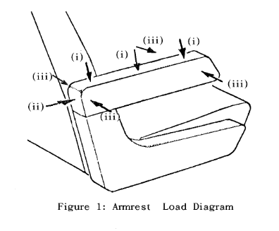
66.2.4. Armrests
Armrests must be tested in the directions shown in Figure 1, using the forces specified below, applied using a semi-cylindrical form of 50 mm radius and a length of 200 mm. Each location must be loaded separately.
66.2.4.1. A vertical load (i) of 1,000 N shall be applied to the armrest at locations within 30 mm of each end and at the centre of the armrest, with the loading form horizontal and transversely across the armrest.
66.2.4.2. A horizontal longitudinal load (ii) of 2,000 N shall be applied to the rear upper 30 mm of each armrest, with the the loading form vertical.
66.2.4.3. A horizontal load (iii) of 1,000 N shall be applied to locations within 30 mm of the ends of the armrest, with the the loading form vertical. These loads shall be applied in both directions to the ‘Forward’ end of the armrest and towards the ‘Seat’ at the rear end of the armrest, and outwards from the ‘Seat’ at the rear end of the armrest if that part of the armrest is exposed in any position of the ‘Seat’.
66.2.4.4. After the specified loads have been applied, no projections or edges may be exposed as a consequence of the application of these loads so as to be contactable by a sphere of 70 mm diameter.
66.2.4.5. All radii contactable by a sphere 165 mm in diameter must present a radius of curvature of at least 5 mm.
66.2.4.6. If any part of the fittings and accessories is made of a material of hardness less than 50 shore A on a rigid backing, the requirements set out in clause 6 apply only to the rigid backing.
66.2.5. The occupant of every ‘Seat’ without another ‘Seat’ meeting this rule immediately in front of it shall be protected by means equivalent to the protection given in paragraph 5.2 of Appendix A.
66.2.5.1. This protection may be provided by either a seat belt or a padded structure providing protection at least equivalent to that provided by a ‘Seat’ back complying with this rule. If a seat belt is used then the strength of the ‘Seat’ shall be such that it is capable of withstanding the seat belt load and the load required by paragraph 5.2 of Appendix A simultaneously.
If a ‘Lap-Sash Belt’ is used no limitations are placed upon the presence or construction of such items as modesty panels in front of the ‘Seat’.
If a ‘Lap Belt’ is used there shall be no obstructions between the ‘Seat’ and a vertical plane 1,300 mm ‘Forward’ of the ‘Seating Reference Point’.
Where padding in accordance with this clause is fitted, for example on a modesty panel, no seat belt is required.
66.2.5.2. In addition, for such a ‘Seat’ fitted with a seat belt the movement of the back of the ‘Seat’ specified in paragraph 5.2 of Appendix A shall be one half of the values specified for a static test.
66.2.5.3. Where seat belts are fitted, all anchorages, including the ‘Final Torso Anchorage’, shall be mounted on the ‘Seat’, except where there is no other ‘Seat’ immediately behind it.
66.2.5.4. A ‘Seat’ with no other ‘Seat’ behind it is required to withstand a horizontal longitudinal force of 10 times the weight of the ‘Seat’ together with the loads of any seat belts mounted on the ‘Seat’.
66.2.6. ‘Seats’ convertible to a sleeper/bunk shall also meet the requirements of the rule in their sleeper/bunk configuration.
Any ‘Seat’ or other device which reclines to or is positioned at more than 45 degrees from the vertical is considered to be a sleeper/bunk.
Compliance with this requirement shall be demonstrated through the use of a test procedure approved by the ‘Administrator’.
66.2.7. A Hybrid III manikin may be used in lieu of the Hybrid II manikin referred to in this rule.
66.2.8. Paragraph 3.2.5 in Annex 4 of Appendix A specifies a force equal to at least 20 N. For the purposes of this rule the force is to be 40 + 20 N.
66.2.9. Paragraph 1.1 of Appendix A specifies requirements for ‘Seats’ which are installed on horizontal planes not differing by more than 6 cm from the floor level of the other forward-facing ‘Seat’ immediately in front of it. Where the difference in height is more than 6 cm the rearmost ‘Seat’ shall be considered as a ‘Seat’ coming within the provisions of clause 66.2.5 and shall either meet the requirements of clause 66.2.5 or shall meet the intent of this Rule to the satisfaction of the ‘Administrator’.
66.3. ALTERNATIVE STANDARDS
Provided that the vehicle and/or its ‘Seats’ comply with the requirements of clauses 66.2.3 to 66.2.9, the technical requirements of ECE R 80/00 “ Strength of Seats & their Anchorages in Large Passenger Vehicles” shall be deemed to be equivalent to the technical requirements of this rule.
66.4. ALTERNATIVE SYSTEMS
Innovative and/or alternative systems may be submitted for approval where the safety of the system can be demonstrated by testing.
Approval of any alternative systems shall be on the basis that, overall, the occupant protection is equal to or greater than that required by this rule.

Regulation No. 80
UNIFORM PROVISIONS CONCERNING THE APPROVAL OF SEATS OF LARGE PASSENGER VEHICLES AND OF THESE VEHICLES WITH REGARD TO THE STRENGTH OF THE SEATS AND THEIR ANCHORAGES
CONTENTS
1. Scope
2. Definitions
3. Application for approval
4. Approval
5. Requirements for a seat type
6. Requirements for a vehicle type
7. Conformity of production
8. Penalties for nonconformity of production
9. Modifications and extension of approval of the seat type and/or the vehicle type
10. Production definitely discontinued
11. Names and addresses of technical services responsible for conducting approval tests and of administrative departments
ANNEXES
Annex 1 Communication concerning ... (seat) ... Regulation No. 80
Annex 2 Communication concerning ... (vehicle) ... Regulation No. 80
Annex 3 Arrangements of approval marks
Annex 4 Test procedures for seats according to paragraph 5 and/or anchorages according to paragraph 6.1.2
Annex 5 Test procedure for the anchorages of a vehicle in application of paragraph 6.1.1
Annex 6 Measurements to be made
Annex 7 Determination of acceptability criteria
Annex 8 Procedure for determining the “H” point and the actual torso angle for seating positions in motor vehicles
1. SCOPE
This Regulation applies to vehicles constructed for the carriage of more than sixteen passengers, in addition to the driver and crew, in respect of:
1.1. Every passenger seat having a reference height of at least 1 m intended to be installed facing forwards and immediately in front of another forward-facing seat on a horizontal plane not differing by more than 6 cm from the floor level of the other forward-facing seat, and tested according to the requirements of paragraph 5.
1.2. The seat anchorages provided in the vehicle and intended to be fitted with the seats indicated in paragraph 1.1. or any other type of seat likely to be fitted on these anchorages and tested according to the requirements of paragraph 6.
2. DEFINITIONS
2.1. “Approval of a seat type” means an approval in relation to the protection of the occupants of forwardfacing seats, the strength of the seats structure and supports;
2.2. “Approval of a vehicle type” means an approval with regard to the strength of the parts of the vehicle structure to which seats are to be secured, and with regard to the installation of seats;
2.3. “Seat type” means a category of seats which do not differ essentially with respect to the following characteristics likely to affect their strength and their aggressivity;
2.3.1. Structure, shape, dimensions and materials of the load bearing parts;
2.3.2. Types and dimensions of the seat back adjustment and locking system;
2.3.3. Dimensions, structure and materials of the attachments and supports (e.g. legs);
2.4. “Vehicle type” means a category of vehicles which do not differ essentially in respect of the constructional features relevant to this Regulation;
2.5. “Seat” means a structure likely to be anchored to the vehicle structure, including its trim and attachment fittings, intended to be used in a vehicle, and to seat one or more adult persons;
2.6. “Individual seat” means a seat designed and constructed for the accommodation of one seated passenger;
2.7. “Double seat” means a seat designed and constructed for the accommodation of two seated passengers side by side, two seats side by side and having no interconnection shall be regarded as two individual seats;
2.8. “Row of seats” means a seat designed and constructed for the accommodation of three or more seated passengers side by side; several individual or double seats arranged side by side shall not be regarded as a row of seats;
2.9. “Seat cushion” means the part of the seat which is arranged almost horizontally and designed to support a seated passenger;
2.10. “Seat-back” means the part of the seat that is almost vertical, designed to support the passenger’s back, shoulders and, possibly, his head;
2.11. “Adjustment system” means the device by which the seat or its parts can be adjusted to a position suited to the seated occupant;
2.12. “Displacement system” means a device enabling the seat or one of its parts to be displaced angularly, laterally or longitudinally without a fixed intermediate position of the seat or one of its parts, to facilitate access by passengers;
2.13. “Locking system” means a device ensuring that the seat and its parts are maintained in the position of use;
2.14. “Anchorage” means a part of the floor or of the body of a vehicle to which a seat may be fixed;
2.15. “Attachment fittings” means bolts or other components used to attach the seat to the vehicle;
2.16. “Trolley” means the test equipment made and used for dynamic reproduction of road accidents involving frontal collision;
2.17. “Auxiliary seat” means a seat for the manikin mounted on the trolley to the rear of the seat to be tested;
2.18. “Reference plane” means the plane passing through the points of contact of the heels of the manikin, used for the determination of the H point and the actual angle of torso for the seating position of motor vehicles according to the prescriptions of annex 8;
This “reference plane” is horizontal.
2.19. “Reference height” means the height of the top of the seat above the reference plane;
2.20. “Manikin”, a manikin corresponding to the specifications for HYBRID II.
3APPLICATION FOR APPROVAL. NOT USED
4. APPROVAL. NOT USED
5. REQUIREMENTS FOR A SEAT TYPE
5.1. Every adjustment and displacement system provided shall incorporate a locking system, which shall operate automatically.
5.2. Each type of seat may be checked by either of the tests described in annex 4. Another suitable test may be used provided that its equivalence with one of the prescribed tests is demonstrated.
The test is to determine:
5.2.1. If the seat occupant(s) is (are) correctly retained by the seat(s) in front of him (them).
This requirement shall be considered satisfied:
5.2.1.1. either, in the case of the test prescribed in paragraph 2 of annex 4, if the forward movement of any part of the trunk and the head of the manikin does not pass beyond the transversal vertical plane situated at 1.6 m from the R point of the auxiliary seat;
5.2.1.2. or, in the case of the test prescribed in paragraph 3 of annex 4, if the maximum displacement of the central point of application of each force prescribed in paragraph 3.2.1. of annex 4 measured in the horizontal plane and in the longitudinal median plane of the relevant seating position does not exceed 400 mm.
5.2.2. If the seat occupant(s) is (are) not seriously injured.
This requirement shall be considered satisfied:
5.2.2.1. either, in the case of the test prescribed in paragraph 2 of annex 4 which uses an instrumented manikin, if the following biomechanical acceptability criteria, determined in accordance with annex 7, are met;
5.2.2.1.1. The head acceptability criterion HAC is less than 500;
5.2.2.1.2. The thorax acceptability criterion (ThAC) is less than 30 g except for periods totalling less than 3 ms;
5.2.2.1.3. The femur acceptability criterion (FAC) is less than 10 kN and the value of 8 kN is not exceeded for periods totalling more than 20 ms;
5.2.2.2. or, in the case of the test prescribed in paragraph 3 of annex 4, if the following energy absorption characteristics are met;
5.2.2.2.1. The maximum displacement of the central point of application of each of the forces prescribed in paragraph 3.2.1. of annex 4, measured as described in paragraph 5.2.1.2., is not less than 100 mm.
5.2.2.2.2 The maximum displacement of the central point of application of each of the forces prescribed in paragraph 3.2.2 of annex 4, measured as described in paragraph 5.2.1.2., is not less than 50 mm.
5.2.3. The seat and the seat mountings are strong enough. This requirement shall be considered satisfied if:
5.2.3.1. No part of the seat, the seat mountings or the accessories becomes completely detached during the test;
5.2.3.2. The seat remains firmly held, even if one or more anchorages is partly detached, and all the locking systems remain locked during the whole duration of the test;
5.2.3.3. After the test no structural part of the seat or accessories has any fracture or sharp or pointed edges or corners likely to cause any bodily injury.
5.3. All fittings forming part of the back of the seat or accessories thereto shall be such as to be unlikely to cause any bodily injury to a passenger during impact. This requirement shall be considered satisfied if any part contactable by a sphere 165 mm in diameter presents a radius of curvature of at least 5 mm.
5.3.1. If any part of the fittings and accessories referred to above is made of a material of hardness less than 50 shore A on a rigid backing, the requirements set out in paragraph 5.3. shall apply only to the rigid backing.
5.3.2. The parts of the back of the seat such as adjustment devices for the seat and accessories shall not be subject to any requirements of paragraph 5.3. if in the position of rest they are situated below a horizontal plane 400 mm above the reference plane, even if the occupant might enter into contact with them.
See also Clauses 66.2.3 and 66.2.4 for other accessory/armrest requirements.
5.4. The adjustment and locking systems shall not be required to be in full working order after the test.
6. REQUIREMENTS FOR A VEHICLE TYPE
6.1. The anchorages for the seats on the vehicle shall be capable of withstanding,
6.1.1. either the test described in annex 5,
6.1.2. or, if a seat is mounted on the part of the vehicle structure being tested, one of the tests prescribed in annex 4. The seat need not be an approved seat provided that it satisfies the requirements of paragraph 5.2.1.
6.2. Permanent deformation, including breakage, of an anchorage or the surrounding area shall be permissible provided the prescribed force has been sustained throughout the prescribed period.
6.3. When there is more than one type of anchorage on a vehicle, each variant shall be tested in order to obtain approval for the vehicle.
6.4. One test may be used to approve simultaneously a seat and a vehicle.
7 CONFORMITY OF PRODUCTION. NOT USED
8. PENALTIES ... PRODUCTION. NOT USED
9. MODIFICATION ... TYPE. NOT USED
10. PRODUCTION ... DISCONTINUED. NOT USED.
11. NAMES ... DEPARTMENTS. NOT USED
Annexes 1, 2 and 3 NOT USED
Annex 4
TEST PROCEDURES FOR SEATS ACCORDING TO PARAGRAPH 5 AND/OR ANCHORAGES ACCORDING TO PARAGRAPH 6.1.2.
1. PREPARATION OF THE SEAT TO BE TESTED
1.1. The seat to be tested shall be mounted:
1.1.1. either on a testing platform representative of the body of a vehicle,
1.1.2. or on a rigid testing platform.
1.2 The anchorage on the testing platform provided for the test seat(s) shall be identical to or have the same characteristics as that used in vehicle(s) in which the seat is intended to be used.
1.3. The seat to be tested shall be complete with all upholstery and accessories. If the seat is fitted with a table, it shall be in the stowed position.
1.4. If adjustable laterally, the seat shall be positioned for maximum extension.
1.5 If adjustable, the seat back shall be adjusted so that the resulting inclination of the torso of the manikin used for determining the H point and the actual torso angle for seating positions in motor vehicles according to annex 8 is as close as possible to that recommended by the manufacturer for normal use or, in the absence of any particular recommendation by the manufacturer, as near as possible to 25 degrees towards the rear in relation to the vertical.
If the seat back is equipped with a head restraint adjustable for height, it shall be in its lowest position.
2. DYNAMIC TESTS
2.1. The testing platform shall be mounted on a trolley.
2.2. Auxiliary seat
The auxiliary seat shall be the same type as the seat being tested and shall be located parallel to and directly behind the seat being tested, the two seats being at the same height, adjusted identically and on a pitch of 75 cm.
2.3. Manikin
A manikin shall be installed behind each seating position of the seat to be tested as follows:
2.3.1. The manikin shall be placed on the auxiliary seat so that its plane of symmetry corresponds to the plane of symmetry of the seating position in question.
2.3.2. The manikin’s hands shall rest on their thighs with their elbows touching the seat back; the legs shall be extended to the maximum and shall, if possible, be parallel; the heels shall touch the floor.
2.3.3. Each manikin required shall be installed on a seat in accordance with the following procedure:
2.3.3.1. the manikin shall be placed on the seat as close as possible to the desired position,
2.3.3.2. a flat rigid surface 76 mm x 76 mm in area shall be placed as low as possible against the front of the manikin’s torso,
2.3.3.3. the flat surface shall be pressed horizontally against the manikin’s torso at a load of between 25 and 35 daN:
2.3.3.3.1. the torso shall be drawn forward by the shoulders to the vertical position, then laid back against the seat back. This operation shall be performed twice,
2.3.3.3.2. without the torso moving, the head shall be placed in a position such that the platform supporting the measuring instruments contained in the head is horizontal and that the median sagittal plane of the head is parallel to that of the vehicle.
2.3.3.4. the flat surface be carefully removed,
2.3.3.5. the manikin shall be moved forward on the seat and the installation procedure described above repeated,
2.3.3.6. if necessary, the position of the lower members shall be corrected,
2.3.3.7. the measuring instruments installed shall not in any way affect the movement of the manikin during impact,
2.3.3.8. the temperature of the system of measuring instruments shall be stabilized before the test and maintained so far as possible within a range between 19oC and 26oC.
2.4. Impact simulation
2.4.1. The impact speed of the trolley shall be between 30 and 32 km/h.
2.4.2. The deceleration of the trolley during the impact test shall be in accordance with the provisions shown in Figure 1 below. Except for intervals totalling less than 3 ms, the deceleration time history of the trolley shall remain between the limit curves shown in Figure 1.
2.4.3. Furthermore, the average deceleration shall be comprised between 6.4 g and 8.5 g.
3. STATIC TESTS
3.1. Test apparatus
3.1.1. This consists of cylindrical surfaces with a radius of curvature equal to 82 ± 3 mm and a width:
3.1.1.1. at least equal to the width of the seat-back of each seating position of the seat to be tested for the upper form,
3.1.1.2. equal to 320 - 0mm, + 10 mm for the lower form as shown in Figure 2 of this annex.
3.1.2. The surface resting against the parts of the seat shall be made of a material the hardness of which is not less than 80 Shore A.
3.1.3. Each cylindrical surface shall be equipped with at least one force transducer able to measure the forces applied in the direction defined in paragraph 3.2.1.1. of this annex.
3.2. Test procedure
3.2.1. A test force to 1,000/H1 + 50 N shall be applied using a device, conforming to paragraph 3.1. of this annex, to the rear part of the seat corresponding to each seating position of the seat.
3.2.1.1. The direction of application of the force shall be situated in the vertical median plane of the seating position concerned, it shall be horizontal and from the rear towards the front of the seat.
3.2.1.2. This direction shall be situated at the height H1 which shall be between 0.70 m and 0.80 m and above the reference plane. The exact height shall be determined by the manufacturer.
3.2.2. A test force equal to 2,000/H2 + 100 N shall be applied simultaneously to the rear part of the seat corresponding to each seating position of the seat in the same vertical plane and in the same direction at the height H2 which shall be between 0.45 and 0.55 m above the reference plane, with a device conforming to paragraph 3.1. of this annex. The exact height shall be determined by the manufacturer.
3.2.3. The test forms shall be maintained as far as possible in contact with the rear of the seat during the application of the forces specified in paragraphs 3.2.1. and 3.2.2. of this annex. They shall be able to pivot in a horizontal plane.
3.2.4. Where a seat consists of more than one seating position, the forces corresponding to each seating position shall be applied simultaneously and there shall be as many upper and lower forms as seating positions.
3.2.5. The initial position of each seating position of each of the forms shall be determined by bringing the test devices into contact with the seat with a force equal to at least 20 N.
3.2.6. The forces indicated in paragraph 3.2.1. and 3.2.2. shall be applied as rapidly as possible and shall be maintained together at the specified value, whatever the deformation, for at least 0.2 seconds.
3.2.7. If the test has been carried out with one or more forces but not with all the forces greater than those specified in paragraphs 3.2.1. and 3.2.2. and if the seat complies with the requirements, the test shall be considered to be satisfied.
Figure 1


Figure 2
Annex 5
TEST PROCEDURE FOR THE ANCHORAGES OF A VEHICLE IN APPLICATION OF PARAGRAPH 6.1.1.
1. TEST APPARATUS
1.1. A rigid structure sufficiently representative of the pedestal of the seat is fixed by the means of fixation (bolts, screws, etc.) provided by the manufacturer to the parts of the structure submitted to the tests.
1.2. If several seat types differing from one another in respect of the distance between the front and back ends of their feet can be mounted on the same anchorage, the test shall be carried out with the shortest footing. This footing shall be described on the communication form.
2. TEST PROCEDURE
2.1. A force F shall be applied:
2.1.1. at a height of 0.75 m above the reference plane and on the vertical line containing the geometrical centre of the surface bounded by the polygon having the different anchorage points as apexes or, if applicable, the extreme anchorages of the seat, by the rigid structure as defined in paragraph 1.1.,
2.1.2. in the horizontal direction and directed to the front of the vehicle,
2.1.3. in a delay as short as possible and while a duration of
shall be maintained for
at least 0.2 s.
2.2. The force F shall be determined by the following formula:
F = (5,000 + 50) × i
where: F is given in N and i represents the number of seating positions of the seat for which the anchorages to be tested are to be approved.
Annex 6
MEASUREMENTS TO BE MADE
1. All measurements necessary shall be made with measurement systems corresponding to the specifications of International Standard ISO 6487 entitled “Technique of measurement in impact tests: Instrumentation” and published in 1980.
2. DYNAMIC TEST
2.1. Measurements to be made on the trolley
The characteristics of the deceleration of the trolley shall be measured, from the accelerations measured on the rigid frame of the trolley, with measurement systems with a CFC of 60.
2.2. Measurements to be made on manikins
The readings of the measuring devices shall be recorded through independent data channels of the following CFC:
2.2.1. Measurements in the head of the manikin
The resultant triaxial acceleration referring to the centre of gravity ( r) shall be measured with a CFC of 600.
2.2.2. Measurements in the thorax of the manikin
The resultant acceleration at the centre of gravity shall be measured with a CFC of 180.
2.2.3. Measurements in the femur of the manikin
The axial compression force shall be measured with a CFC of 600.
3. STATIC TEST
Forces shall be measured with a CFC of 600 Not Applicable
Annex 7
DETERMINATION OF ACCEPTABILITY CRITERIA
1. HEAD ACCEPTABILITY CRITERION (HAC)
1.1. This acceptability criterion (HAC) is calculated on the basis of the resultant tri-axial acceleration measured according to annex 6, paragraph 2.2.1. by the following expression:

in which t1 and t2 are any values of time during the test, HAC being maximum value for any interval t1, t2. The values of t1 and t2 are expressed in seconds.
2. THORAX ACCEPTABILITY CRITERION (ThAC)
2.1. This criterion is determined by the absolute value of the resultant acceleration, expressed in g and measured according to annex 6, paragraph 2.2.2., and by the acceleration period, expressed in ms.
3. FEMUR ACCEPTABILITY CRITERION (FAC)
This criterion is determined by the compression load expressed in kN, transmitted axially on each femur of
the manikin and measured according to annex 6, paragraph 2.2.3., and by the duration of the compression load, expressed in ms.
Annex 8
PROCEDURE FOR DETERMINING THE “H” POINT AND THE ACTUAL TORSO ANGLE FOR SEATING POSITION IN MOTOR VEHICLES
1. PURPOSE
The procedure described in this annex is used to establish the “H” point location and the actual torso angle for one or several seating positions in a motor vehicle and to verify the relationship of measured data to design specifications given by the vehicle manufacturer.
2. DEFINITIONS
For the purposes of this annex:
2.1. “Reference data” means one or several of the following characteristics of a seating position:
2.1.1. the “H” point and the “R” point and their relationship;
2.1.2. the actual torso angle and the design torso angle and their relationship;
2.2. “Three-dimensional ‘H’ point machine” (3 DH machine) means the device used for the determination of “H” points and actual torso angles. This device is described in appendix 1 to this annex;
2.3. “‘H’ point” means the pivot centre of the torso and thigh of the 3 DH machine installed in the vehicle seat in accordance with paragraph 4 below. The “H” point is located in the centre of the centreline of the device which is between the “H” point sight buttons on either side of the 3 DH machine. The “H” point corresponds theoretically to the “R” point (for tolerances see paragraph 3.2.2. below). Once determined in accordance with the procedure described in paragraph 4, the “H” point is considered fixed in relation to the seat-cushion structure and to move with it when the seat is adjusted;
2.4. “R point” or “seating reference point” means a design point defined by the vehicle manufacturer for each seating position and established with respect to the three-dimensional reference system;
2.5. “Torso line” means the centreline of the probe of the 3 DH machine with the probe in the fully rearward position;
2.6. “Actual torso angle” means the angle measured between a vertical line through the “H” point and the torso line using the back angle quadrant on the 3 DH machine. The actual torso angle corresponds theoretically to the design torso angle (for tolerances see paragraph 3.2.2. below);
2.7. “Design torso angle” means the angle measured between a vertical line through the “R” point and the torso line in a position which corresponds to the design position of the seat-back established by the vehicle manufacturer;
2.8. “Centreplane of occupant” (C/LO) means the median plane of the 3 DH machine positioned in each designated seating position; it is represented by the co-ordinate of the “H” point on the “Y” axis. For individual seats, the centreplane of the seat coincides with the centreplane of the occupant. For other seats, the centreplane of the occupant is specified by the manufacturer;
2.9. “Three-dimensional reference system” means a system as described in appendix 2 to this annex;
2.10. “Fiducial marks” are physical points (holes, surfaces, marks or indentations) on the vehicle body as defined by the manufacturer;
2.11. “Vehicle measuring attitude” means the position of the vehicle as defined by the coordinates of fiducial marks in the three-dimensional reference system.
3. REQUIREMENTS
3.1. Data presentation
For each seating position where reference data are required in order to demonstrate compliance with the provisions of the present Regulation, all or an appropriate selection of the following data shall be presented in the form indicated in appendix 3 to this annex:
3.1.1. the co-ordinates of the “R” point relative to the three-dimensional reference system;
3.1.2. the design torso angle;
3.1.3. all indications necessary to adjust the seat (if it is adjustable) to the measuring position set out in paragraph 4.3 below;
3.2. Relationship between measured data and design specifications
3.2.1. The co-ordinates of the “H” point and the value of the actual torso angle obtained by the procedure set out in paragraph 4 below shall be compared, respectively, with the co-ordinates of the “R” point and the value of the design torso angle indicated by the vehicle manufacturer;
3.2.2. The relative positions of the “R” point and the “H” point and the relationship between the design torso angle and the actual torso angle shall be considered satisfactory for the seating position in question if the “H” point, as defined by its co-ordinates, lies within a square of 50 mm side length with horizontal and vertical sides whose diagonals intersect at the “R” point, and if the actual torso angle is within 5 degrees of the design torso angle;
3.2.3. If these conditions are met, the “R” point and the design torso angle shall be used to demonstrate compliance with the provisions of this Regulation;
3.2.4. If the “H” point or the actual torso angle does not satisfy the requirements of paragraph 3.2.2. above, the “H” point and the actual torso angle shall be determined twice more (three times in all). If the results of two of these three operations satisfy the requirements, the conditions of paragraph 3.2.3. above shall apply;
3.2.5. If the results of at least two of the three operations described in paragraph 3.2.4. above do not satisfy the requirements of paragraph 3.2.2. above, or if the verification cannot take place because the vehicle manufacturer has failed to supply information regarding the position of the “R” point or regarding the design torso angle, the centroid of the three measured points or the average of the three measured angles shall be used and be regarded as applicable in all cases where the “R” point or the design torso angle is referred to in this Regulation.
4. PROCEDURE FOR “H” POINT AND ACTUAL TORSO ANGLE DETERMINATION
4.1. The vehicle shall be pre-conditioned at the manufacturer’s discretion, at a temperature of 20 ± 10oC to ensure that the seat material reaches room temperature. If the seat to be checked has never been sat upon, a 70 to 80 kg person or device shall sit on the seat twice for one minute to flex the cushion and back. At the manufacturer’s request, all seat assemblies shall remain unloaded for a minimum period of 30 min. prior to installation of the 3 DH machine;
4.2. The vehicle shall be at the measuring attitude defined in paragraph 2.11. above;
4.3. The seat, if it is adjustable, shall be adjusted first to the rearmost normal driving or riding position, as indicated by the vehicle manufacturer, taking into consideration only the longitudinal adjustment of the seat, excluding seat travel used for purposes other than normal driving or riding positions. Where other modes of seat adjustment exist (vertical, angular, seat-back, etc.) these will be then adjusted to the position specified by the vehicle manufacturer. For suspension seats, the vertical position shall be rigidly fixed corresponding to a normal driving position as specified by the manufacturer;
4.4. The area of the seating position contacted by the 3 DH machine shall be covered by a muslin cotton, of sufficient size and appropriate texture, described as a plain cotton fabric having 18.9 threads per cm2 and weighing 0.228 kg/m2 or knitted or non-woven fabric having equivalent characteristics;
If test is run on a seat outside the vehicle, the floor on which the seat is placed shall have the same essential characteristics as the floor of the vehicle in which the seat is intended to be used;
4.5. Place the seat and back assembly of the 3 DH machine so that the centreplane of the occupant (C/LO) coincides with the centreplane of the 3 DH machine. At the manufacturer’s request, the 3 DH machine may be moved inboard with respect to the C/LO if the 3 DH machine is located so far outboard that the seat edge will not permit levelling of the 3 DH machine;
4.6. Attach the foot and lower leg assemblies to the seat pan assembly, either individually or by using the T-bar and lower leg assembly. A line through the “H” point sight buttons shall be parallel to the ground and perpendicular to the longitudinal centreplane of the seat;
4.7. Adjust the feet and leg positions of the 3 DH machine as follows:
4.7.1. Designated seating position: driver and outside front passenger
4.7.1.1. Both feet and leg assemblies shall be moved forward in such a way that the feet take up natural positions on the floor, between the operating pedals if necessary. Where possible the left foot shall be located approximately the same distance to the left of the centreplane of the 3DH machine as the right foot is to the right. The spirit level verifying the transverse orientation of the 3 DH machine is brought to the horizontal by readjustment of the seat pan if necessary, or by adjusting the leg and foot assemblies towards the rear. The line passing through the “H” point sight buttons shall be maintained perpendicular to the longitudinal centreplane of the seat;
4.7.1.2. If the left leg cannot be kept parallel to the right leg and the left foot cannot be supported by the structure, move the left foot until it is supported. The alignment of the sight buttons shall be maintained;
4.7.2. Designated seating position: outboard rear
For rear seats or auxiliary seats, the legs are located as specified by the manufacturer. If the feet then rest on parts of the floor which are at different levels, the foot which first comes into contact with the front seat shall serve as a reference and the other foot shall be so arranged that the spirit level giving the transverse orientation of the seat of the device indicates the horizontal;
4.7.3. Other designated seating positions:
The general procedure indicated in paragraph 4.7.1. above shall be followed except that the feet shall be placed as specified by the vehicle manufacturer.
4.8. Apply lower leg and thigh weights and level the 3 DH machine;
4.9. Tilt the back pan forward against the forward stop and draw the 3 DH machine away from the seat-back using the T‑bar. Reposition the 3 DH machine on the seat by one of the following methods:
4.9.1. If the 3 DH machine tends to slide rearward, use the following procedure. Allow the 3 DH machine to slide rearward until a forward horizontal restraining load on the T-bar is no longer required, i.e. until the seat pan contacts the seat-back. If necessary, reposition the lower leg;
4.9.2. If the 3 DH machine does not tend to slide rearward, use the following procedure. Slide the 3 DH machine rearwards by applying a horizontal rearward load to the T-bar until the seat pan contacts the seatback (see figure 2 of appendix 1 to this annex);
4.10. Apply a 100 ± 10 N load to the back and pan assembly of the 3 DH machine at the intersection of the hip angle quadrant and the T–bar housing. The direction of load application shall be maintained along a line passing by the above intersection to a point just above the thigh bar housing (see Figure 2 of appendix 1 to this annex). Then carefully return the back pan to the seat–back. Care must be exercised throughout the remainder of the procedure to prevent the 3 DH machine from sliding forward;
4.11. Install the right and left buttock weights and then, alternately, the eight torso weights. Maintain the 3 DH machine level;
4.12. Tilt the back pan forward to release the tension on the seat-back. Rock the 3 DH machine from side to side through 10o arc (5O to each side of the vertical centreplane) for three complete cycles to release any accumulated friction between the 3 DH machine and the seat;
During the rocking action, the T-bar of the 3 DH machine may tend to diverge from the specified horizontal and vertical alignment. The T-bar must therefore be restrained by applying an appropriate lateral load during the rocking motions. Care shall be exercised in holding the T-bar and rocking the 3 DH machine to ensure that no inadvertent exterior loads are applied in a vertical or fore and aft direction;
The feet of the 3 DH machine are not to be restrained or held during this step. If the feet change position, they should be allowed to remain in that attitude for the moment.
Carefully return the back pan to the seat-back and check the two spirit levels for zero position. If any movement of the feet has occurred during the rocking operation of the 3 DH machine, they must be repositioned as follows:
Alternatively, lift each foot off the floor the minimum necessary amount until no additional foot movement is obtained. During this lifting, the feet are to be free to rotate; and no forward or lateral loads are to be applied. When each foot is placed back in the down position, the heel is to be in contact with the structure designed for this;
Check the lateral spirit level for zero position; if necessary, apply a lateral load to the top of the back pan sufficient to level the 3 DH machine’s seat pan on the seat;
4.13. Holding the T-bar to prevent the 3 DH machine from sliding forward on the seat cushion, proceed as follows:
(a) return the back pan to the seat-back;
(b) alternately apply and release a horizontal rearward load, not to exceed 25 N, to the back angle bar at a height approximately at the centre of the torso weights until the hip angle quadrant indicates that a stable position has been reached after load release. Care shall be exercised to ensure that no exterior downward or lateral loads are applied to the 3 DH machine. If another level adjustment of the 3 DH machine is necessary, rotate the back pan forward, re-level, and repeat the procedure from 4.12.;
414. Take all measurements:
4.14.1. The co-ordinates of the “H” point are measured with respect to the three-dimensional reference system;
4.14.2. The actual torso angle is read at the back angle quadrant of the 3 DH machine with the probe in its fully rearward position;
4.15. If a re-run of the installation of the 3 DH machine is desired, the seat assembly should remain unloaded for a minimum period of 30 min prior to the re-run. The 3 DH machine should not be left loaded on the seat assembly longer than the time required to perform the test;
4.16. If the seats in the same row can be regarded as similar (bench seat, identical seats, etc.) only one “H” point and one “actual torso angle” shall be determined for each row of seats, the 3 DH machine described in appendix 1 to this annex being seated in a place regarded as representative for the row. This place shall be:
4.16.1. in the case of the front row, the driver’s seat;
4.16.2 in the case of the rear row or rows, an outer seat.
Annex 8 Appendix 1
DESCRIPTION OF THE THREE DIMENSIONAL “H” POINT MACHINE
(3 DH machine)
1. Back and seat pans
The back and seat pans are constructed of reinforced plastic and metal; they simulate the human torso and thigh and are mechanically hinged at the “H” point. A quadrant is fastened to the probe hinged at the “H” point to measure the actual torso angle. An adjustable thigh bar, attached to the seat pan, establishes the thigh centreline and serves as a baseline for the hip angle quadrant.
2. Body and leg elements
Lower leg segments are connected to the seat pan assembly at the T-bar joining the knees, which is a lateral extension of the adjustable thigh bar. Quadrants are incorporated in the lower leg segments to measure knee angles. Shoe and foot assemblies are calibrated to measure the foot angle. Two spirit levels orient the device in space. Body element weights are placed at the corresponding centres of gravity to provide seat penetration equivalent to a 76 kg male. All joints of the 3 DH machine should be checked for free movement without encountering noticeable friction.
Annex 8
Appendix 1

Figure 1 - 3 DH machine elements designation
Annex 8
Appendix 1
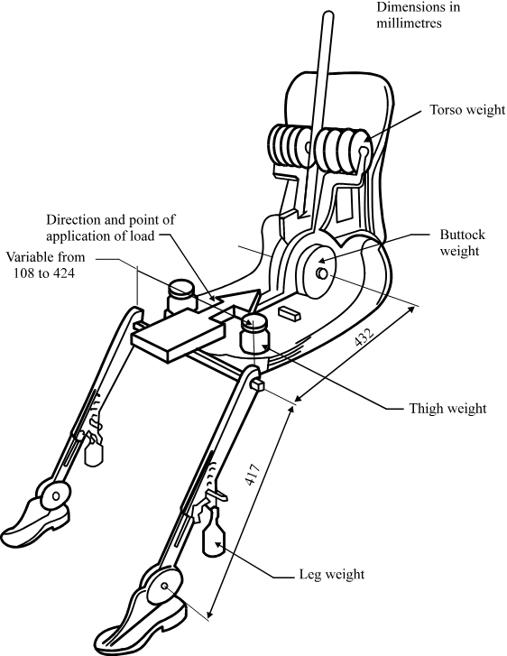
Figure 2 - Dimensions of the 3 DH machine elements and load distribution
Annex 8
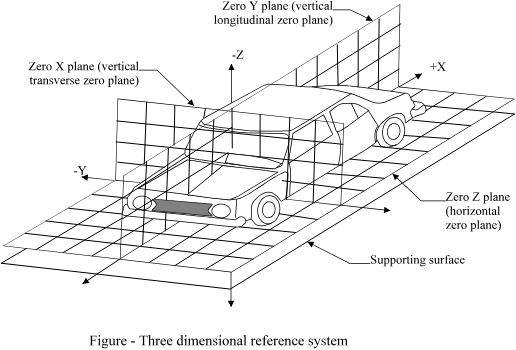
Appendix 2
THREE-DIMENSIONAL REFERENCE SYSTEM
1. The three-dimensional reference system is defined by three orthogonal planes established by the vehicle manufacturer (see figure).
2. The vehcile measureing attitude is established by positioning the vehicle on the supporting surface such that the co-ordinates of the fiducial marks correspond to the values indicated by the manufacturer.
3. The co-ordinates of the “R” point and the “H” point are established in relation to the fiduciul marks defined by the vehicle manufacturer.
Annex 8 Appendix 3
REFERENCE DATA CONCERNING SEATING POSITIONS
1. Coding of reference data
Reference data are listed consecutively for each seating position. Seating positions are identified by a two-digit code. The first digit is an Arabic numeral and designates the row of seats, counting from the front to the rear of the vehicle. The second digit is a capital letter which designates the location of the seating position in a row, as viewed in the direction of forward motion of the vehicle; the following letters shall be used:
L = left
C = centre
R = right
2. Description of vehicle measuring attitude
2.1. Coordinates of fiducial marks
X ............................
Y ............................
Z ............................
3. List of reference data
3.1. Seating position: ..........................
3.1.1. Coordinates of “R” point
X ............................
Y ............................
Z ............................
3.1.2. Design torso angle: ........................
3.1.3. Specifications for seat adjustment
horizontal : .................
vertical : .................
angular : .................
torso angle: .................
Note: List reference data for further seating positions under 3.2, 3.3, etc.