Vehicle Standard (Australian Design Rule 14/0214/02 – Rear Vision MirrorsRear Vision Mirrors) 20062006
I, JAMES ERIC LLOYD, Minister for Local Government, Territories and Roads, determine this vehicle standard under subsection 7 (1) of the Motor Vehicle Standards Act 1989.
Dated 8 August 2006
[SIGNED]
James Eric Lloyd
Minister for Local Government, Territories and Roads
CONTENTS
1. legislative provisions..............................................
2. SCOPE.........................................................
3. APPLICABILITY AND IMPLEMENTATION.........................
4. DEFINITIONS...................................................
5. REQUIREMENTS................................................
6. EXEMPTIONS TO APPENDIX A...................................
7. EXEMPTIONS TO APPENDIX B...................................
8. ALTERNATIVE STANDARDS.....................................
Appendix A – UNECE R46................................................
appendix B – UNECE R81................................................
Appendix C – ADR 14/02 - Rear Vision Mirrors...............................
1. definitions......................................................
2. REQUIREMENTS FOR LEP; MA; MB; MC; AND MD1 VEHICLES ONLY
3. REQUIREMENTS FOR VEHICLES OF CATEGORY LEG; NA AND MD2 ONLY
4. REQUIREMENTS FOR MD3; MD4; ME; NB; AND NC VEHICLES ONLY.
5. REQUIREMENTS FOR LA; LB; LC; LD AND LEM GROUP VEHICLES ONLY
6. ADDITIONAL EXTERNAL REAR VISION MIRRORS.................
- legislative provisions
- NAME OF STANDARD
- This Standard is the Vehicle Standard (Australian Design Rule 14/02 – Rear Vision Mirrors) 2006.
- This Standard may also be cited as Australian Design Rule 14/02 — Rear Vision Mirrors.
- COMMENCEMENT
- This Standard commences on the day after it is registered.
- REPEAL
- This Standard repeals each vehicle standard with the name Australian Design Rule 14/02 — Rear Vision Mirrors that is:
(a) made under section 7 of the Motor Vehicle Standards Act 1989; and
(b) in force at the commencement of this Standard.
1.3.2. This Standard also repeals each instrument made under section 7 of the Motor Vehicle Standards Act 1989 that creates a vehicle standard with the name Australian Design Rule 14/02 — Rear Vision Mirrors, if there are no other vehicle standards created by that instrument, or amendments to vehicle standards made by that instrument, that are still in force at the commencement of this Standard.
2. SCOPE
2.1. The function of this vehicle standard is to specify requirements for rear vision mirrors to provide the driver with a clear and reasonably unobstructed view to the rear.
3. APPLICABILITY AND IMPLEMENTATION
3.1. This vehicle standard applies to the design and construction of vehicles as set out in 3.3 Applicability Table.
3.2. Provided that they were tested to the SAE test procedure J964a August 1974, and meet the curvature specifications, vehicles certified to the requirements of any of the Acceptable Prior Rules as shown below in the Applicability Table are deemed to comply with this Rule.
3.3. Applicability Table
Vehicle Category | ADR Category Code | UNECE Category Code | Manufactured on or After | Acceptable Prior Rules |
Moped 2 wheels | LA | L1 | 1 March 1993 | /00, /01 |
Moped 3 wheels | LB | L2 | 1 March 1993 | /00, /01 |
Motor cycle | LC | L3 | 1 March 1993 | /00, /01 |
Motor cycle and sidecar | LD | L4 | 1 March 1993 | /00, /01 |
Motor tricycle | LE | L5 | | |
| LEM | | 1 March 1993 | /00, /01 |
| LEP | | 1 July 1992 | Nil |
| LEG | | 1 July 1992 | Nil |
Passenger car | MA | M1 | 1 Jan 1993 | /00, /01 |
Forward-control passenger vehicle | MB | M1 | 1 Jan 1993 | /00, /01 |
Off-road passenger vehicle | MC | M1 | 1 Jan 1993 | /00, /01 |
Light omnibus | MD | M2 | | |
| up to 3.5 tonnes ‘GVM’ and up to 12 seats | MD1 | | 1 July 1992 | /00, /01 |
| up to 3.5 tonnes ‘GVM’ and more than 12 seats | MD2 | | 1 July 1992 | /00, /01 |
| over 3.5 tonnes and up to 4.5 tonnes ‘GVM’ | MD3 | | 1 July 1992 | /00, /01 |
| over 4.5 tonnes and up to 5 tonnes ‘GVM’ | MD4 | | 1 July 1992 | /00, /01 |
Heavy omnibus | ME | M3 | 1 July 1992 | /00, /01 |
Light goods vehicle | NA | N1 | 1 July 1992 | /00, /01 |
Medium goods vehicle | NB | N2 | | |
| over 3.5 tonnes up to 4.5 tonnes ‘GVM’ | NB1 | | 1 July 1992 | /00, /01 |
| over 4.5 tonnes up to 12 tonnes ‘GVM’ | NB2 | | 1 July 1992 | /00, /01 |
Heavy goods vehicle | NC | N3 | 1 July 1992 | /00, /01 |
Very light trailer | TA | O1 | Not Applicable | |
Light trailer | TB | O2 | Not Applicable | |
Medium trailer | TC | O3 | Not Applicable | |
Heavy trailer | TD | O4 | Not Applicable | |
4. DEFINITIONS
4.1. Refer to Section 2 and 12 of Appendix A,
4.2. Section 3 of Appendix B, and
4.3. Section 1 of Appendix C
5. REQUIREMENTS
5.1. Vehicles of applicable categories listed in clause 3.3 complying with one of the following clauses (5.1.1 – 5.1.4) shall be accepted as complying with this vehicle standard.
5.1.1. For M and N category, and LE category with bodywork that partially or wholly encloses the driver, Appendix A as varied by section 6 Exemptions to Appendix A.
5.1.2. For LA, LB, LC and LD category, and LE category without bodywork that partially or wholly encloses the driver, Appendix B as varied by section 7 Exemptions to Appendix B.
5.1.3. For any vehicle category, Appendix C.
5.1.4. The technical requirements of an alternative standard specified in section 8.
6. EXEMPTIONS TO APPENDIX A
6.1. The following provisions of Appendix A do not apply to this vehicle standard.
Section 3 Application for approval
Section 4 Markings
Section 5 Approval
Section 7 Modification of the type of device for indirect vision and extension of approval
Section 8 Conformity of production
Section 9 Penalties for non-conformity of production
Section 10 Production definitely discontinued
Section 11 Names and addresses of technical services responsible for conducting approval tests, and of administrative departments
Section 13 Application for approval
Section 14 Approval
Section 16 Modifications of the vehicle type and extension of approval
Section 17 Conformity of production
Section 18 Penalties for non-conformity of production
Section 19 Production definitely discontinued
Section 20 Names and addresses of technical services responsible for conducting approval tests, and of administrative departments
Section 21 Transitional arrangements
Annex 1 Information document for type-approval of a device for indirect vision
Annex 2 Information document for type-approval of a vehicle with respect to the installation of devices for indirect vision
Annex 3 Communication
Annex 4 Communication
Annex 5 Arrangement of approval mark of a device for indirect vision
6.2. Class VI mirrors are optional for all vehicles (see table in clause 15.2.1.1.1).
7. EXEMPTIONS TO APPENDIX B
7.1. The following provisions of Appendix B do not apply to this vehicle standard.
Section 3 Application for approval
Section 4 Markings
Section 5 Approval
Section 9 Conformity of production
Section 10 Penalties for non-conformity of production
Section 11 Modification and extension of approval of the type of rear view mirror
Section 12 Production definitely discontinued
Section 14 Application for approval
Section 15 Approval
Section 17 Conformity of production
Section 18 Penalties for non-conformity of production
Section 19 Modifications and extension of approval of the vehicle type
Section 20 Production definitely discontinued
Section 21 Names and addresses of technical services responsible for conducting approval tests, and of administrative departments
Annex 1 Communication
Annex 2 Communication
Annex 3 Arrangement of the rear view mirror approval mark
Annex 4 Arrangements of the vehicle approval mark concerning the installation of rear view mirrors
Annex 7 Control of the conformity of production
8. ALTERNATIVE STANDARDS
8.1. UNECE R46 UNIFORM PROVISIONS CONCERNING THE APPROVAL OF DEVICES FOR INDIRECT VISION REAR VIEW MIRRORS, AND OF MOTOR VEHICLES WITH REGARD TO THE INSTALLATION OF THESE DEVICES, up to and including the /02 series of amendments entered into force 23 June 2005.
8.2. UNECE R81 UNIFORM PROVISIONS CONCERNING THE APPROVAL OF REAR VIEW MIRRORS AND OF TWO WHEELED POWER DRIVEN VEHICLES WITH OR WITHOUT SIDE CAR, WITH REGARD TO THE INSTALLATION OF REAR VIEW MIRRORS ON HANDLEBARS, up to and including the /00 series of amendments.
Appendix A – UNECE R46
AGREEMENT
CONCERNING THE ADOPTION OF UNIFORM TECHNICAL PRESCRIPTIONS FOR WHEELED VEHICLES, EQUIPMENT AND PARTS WHICH CAN BE FITTED AND/OR BE USED ON WHEELED VEHICLES AND THE CONDITIONS FOR RECIPROCAL RECOGNITION OF APPROVALS GRANTED ON THE BASIS OF THESE PRESCRIPTIONS /
(Revision 2, including the amendments which entered into force on 16 October 1995)
_________
Addendum 45: Regulation No. 46
Revision 2
Incorporating all valid text up to:
Corrigendum 2 to Revision 1 of the Regulation, subject of Depositary Notification C.N.232.1992.TREATIES-32 dated 11 September 1992 (French only)
Supplement 2 to the 01 series of amendments - Date of entry into force: 27 August 1996
Supplement 3 to the 01 series of amendments – Date of entry into force: 20 September 1994
Supplement 4 to the 01 series of amendments – Date of entry into force: 3 January 1998
UNIFORM PROVISIONS CONCERNING THE APPROVAL OF DEVICES FOR
INDIRECT VISION AND OF MOTOR VEHICLES WITH REGARD TO
THE INSTALLATION OF THESE DEVICES

_________
UNITED NATIONS
Regulation No. 46
UNIFORM PROVISIONS CONCERNING THE APPROVAL OF DEVICES FOR
INDIRECT VISION AND OF MOTOR VEHICLES WITH REGARD TO
THE INSTALLATION OF THESE DEVICES
CONTENTS
REGULATION Page
1. Scope ................................................................6
I. DEVICES FOR INDIRECT VISION
2. Definitions ............................................................6
3. Application for approval .................................................9
4. Markings .............................................................9
5. Approval .............................................................9
6. Requirements .........................................................11
6.1. Mirrors ..............................................................11
6.2. Devices for indirect vision other than mirrors ................................18
7. Modification of the type of device for indirect vision and extension of approval.....19
9. Penalties for non‑conformity of production ..........................20
10. Production definitely discontinued ........................................20
11. Names and addresses of technical services responsible for conducting
approval tests, and of administrative departments.............................21
II. INSTALLATION OF DEVICES FOR INDIRECT VISION
12. Definitions ...........................................................21
13. Application for approval ................................................22
14. Approval ............................................................22
CONTENTS (continued)
15. Requirements .........................................................23
16. Modifications of the vehicle type and extension of approval ....................36
17. Conformity of production ...............................................37
18. Penalties for non‑conformity of production ..........................37
19. Production definitely discontinued .............................................37
20. Names and addresses of technical services responsible for conducting
approval tests, and of administrative departments ............................38
21. Transitional provisions .................................................38
Annex 1 - Model of information document for type approval of a device
for indirect vision .................................................40
Annex 2 - Model of information document for type approval of vehicle with
respect to the installation of devices for indirect vision .....................42
Annex 3 - Communication concerning the approval or refusal or
extension or withdrawal of approval or production
definitely discontinued of a type of device for indirect vision,
pursuant to Regulation No. 46 ........................................45
Annex 4 - Communication concerning the approval or refusal or
extension or withdrawal of approval or production
definitely discontinued of a vehicle type with regard
to the installation of devices for indirect vision, pursuant to
Regulation No. 46 ..................................................47
Annex 5 - Arrangement of approval mark for a device for indirect vision...............50
Annex 6 - Test method for determining reflectivity ................................51
Annex 7 - Procedure for determining the radius of curvature "r" of the
reflecting surface of a mirror..........................................57
CONTENTS (continued)
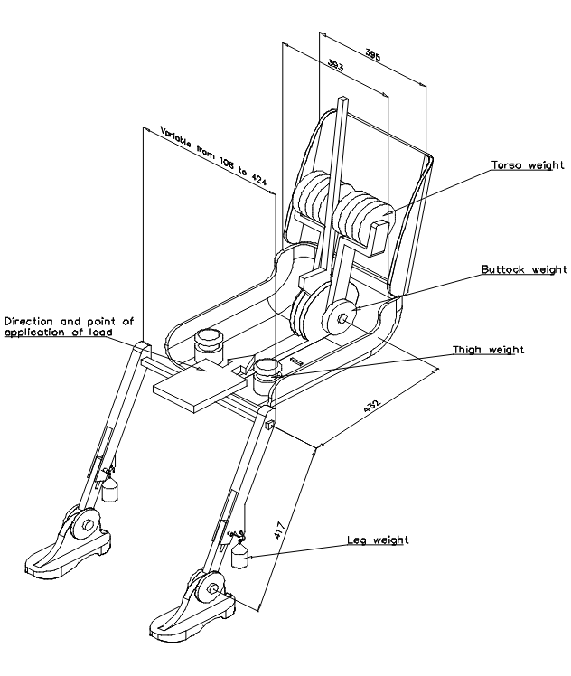
Annex 8 - Procedure for determining the "H" point and the actual
torso angle for seating positions in motor vehicles ........................59
Annex 8 ‑ Appendix 1 Description of the Three-Dimensional "H" Point Machine
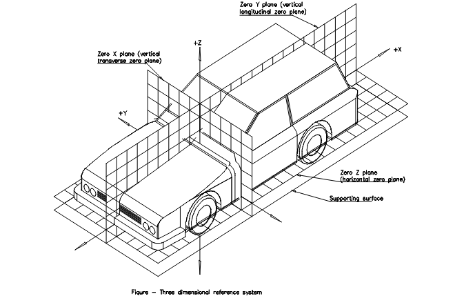
Annex 8 – Appendix 2 Three-dimensional Reference System
Annex 8 – Appendix 3 Reference Data Concerning Seating Positions
Annex 9 (reserved) ........................................................71
Annex 10 - Calculation of the detection distance ...................................72
1. SCOPE
This Regulation applies,
1.1. to devices for indirect vision intended to be installed on motor vehicles of categories M and N / and to all other motor vehicles having less than four wheels fitted with bodywork which partly or wholly encloses the driver and,
1.2. to the installation of devices for indirect vision on:
1.2.1. motor vehicles of categories M and N;
1.2.2. all other motor vehicles having less than four wheels when fitted with bodywork which partly or wholly encloses the driver.
- DEVICES FOR INDIRECT VISION
2. DEFINITIONS
For the purposes of this Regulation:
2.1. "Devices for indirect vision" means devices to observe the traffic area adjacent to the vehicle which cannot be observed by direct vision. These can be conventional mirrors, camera-monitors or other devices able to present information about the indirect field of vision to the driver.
2.1.1 "Mirror" means any device, excluding devices such as periscopes, intended to give a clear view to the rear, side or front of the vehicle within the fields of vision defined in paragraph 15.2.4.
2.1.1.1. "Interior mirror" means a device as defined in paragraph 2.1., which can be fitted in the passenger compartment of a vehicle.
2.1.1.2. "Exterior mirror" means a device as defined in paragraph 2.1., which can be mounted on the external surface of a vehicle.
2.1.1.3. "Surveillance mirror" means a mirror other than the ones defined in paragraph 2.1.1. which can be fitted to the inside or outside of the vehicle in order to provide fields of vision other than those specified in paragraph 15.2.4.
2.1.1.4. "r" means the average of the radii of curvature measured over the reflecting surface, in accordance with the method described in Annex 7.
2.1.1.5. "The principal radii of curvature at one point on the reflecting surface (ri)" means the values obtained with the apparatus defined in Annex 7, measured on the arc of the reflecting surface passing through the centre of this surface parallel to the segment b, as defined in paragraph 6.1.2.1.2.1. and on the arc perpendicular to this segment.
2.1.1.6. "The radius of curvature at one point on the reflecting surface (rp)" means the arithmetical average of the principal radii of curvature ri and ri i.e.:

2.1.1.7. "Spherical surface" means a surface, which has a constant and equal radius in all directions
2.1.1.8. "Aspherical surface" means a surface, which has only in one plane a constant radius.
2.1.1.9. "Aspherical mirror” means a mirror composed of a spherical and an aspherical part, in which the transition of the reflecting surface from the spherical to the aspherical part has to be marked. The curvature of the main axis of the mirror is defined in the x/y coordinate system defined by the radius of the spherical primary calotte with:

R: nominal radius in the spherical part
k: constant for the change of curvature
a: constant for the spherical size of the spherical primary calotte
2.1.1.10. "Centre of the reflecting surface" means the centre of the visible area of the reflecting surface.
2.1.1.11. "The radius of curvature of the constituent parts of the mirror" means the radius "c" of the arc of the circle which most closely approximates to the curved form of the part in question.
2.1.1.12. "Class of mirror" means all devices having one or more common characteristics or functions. They are classified as follows:
- Class I: "Interior rear-view mirror", giving the field of vision defined in paragraph 15.2.4.1.
- Class II and III: "Main exterior rear-view mirror", giving the fields of vision defined in paragraphs 15.2.4.2. and 15.2.4.3.
- Class IV: "Wide-angle exterior mirror", giving the field of vision defined in paragraph 15.2.4.4.
- Class V: "Close-proximity exterior mirror", giving the field of vision defined in paragraph 15.2.4.5.
- Class VI: "Front mirror", giving the field of vision defined in paragraph 15.2.4.6.
2.1.2. "Camera-monitor device for indirect vision" means a device as defined in paragraph 2.1., where the field of vision is obtained by means of a camera-monitor combination as defined in paragraphs 2.1.2.1. and 2.1.2.2.
2.1.2.1. "Camera" means a device that renders an image of the outside world by means of a lens onto a light-sensitive electronic detector that then converts this image into a video signal.
2.1.2.2. "Monitor" means a device that converts a video signal into images that are rendered into the visual spectrum.
2.1.2.3. "Detection" means the ability to distinguish an object from its background/surroundings at certain distance.
2.1.2.4. "Luminance" contrast means the brightness ratio between an object and its immediate background/surrounding that allows the object to be distinguished from its background/surroundings.
2.1.2.5. "Resolution" means the smallest detail that can be discerned with a perceptual system, i.e. perceived as separate from the larger whole. The resolution of the human eye is indicated as "visual acuity".
2.1.2.6. "Critical object" means a circular object with a diameter D0 = 0.8 m. /
2.1.2.7. "Critical perception" means the level of perception that the human eye is generally capable of achieving under various conditions. For traffic conditions the limiting value for a critical perception is eight arc-minutes of visual angle.
2.1.2.8. "Field of vision" means the section of the tri-dimensional space in which a critical object can be observed and rendered by the device for indirect vision. This is based on the view on ground level offered by a device and might possibly be limited on the basis of the applicable maximum detection distance of the device.
2.1.2.9. "Detection distance" means the distance measured at ground level from the viewing reference point to the extreme point at which a critical object can just be perceived (the limiting value for a critical perception just barely achieved).
2.1.2.10. "Critical field of vision" means the area in which a critical object has to be detected by means of a device for indirect vision and that is defined by an angle and one or more detection distances.
2.1.2.11. "Viewing reference point" means the point linked to the vehicle to which the prescribed field of vision is related. This point is the projection on the ground of the intersection of a vertical plane passing through the driver's ocular points with a plane parallel to the median longitudinal plane of the vehicle situated 20 cm outside the vehicle.
2.1.2.12. "Visual spectrum" means light with a wavelength within the range of the perceptual limits of the human eyes: 380‑780 nm.
2.1.3. "Other devices for indirect vision" means devices as defined in paragraph 2.1., where the field of vision is not obtained by means of a mirror or a camera-monitor type device for indirect vision.
2.1.4. "Type of device for indirect vision" means devices that do not differ on the following essential characteristics:
- design of the device inclusive, if pertinent, the attachment to the bodywork;
- in case of mirrors the class, the shape, the dimensions and radius of curvature of the mirror's reflecting surface;
- in case of camera-monitor devices the detection distance and the range of vision.
3. APPLICATION FOR APPROVAL
3.1. The application for approval of a type of device for indirect vision shall be submitted by the holder of the trade name or mark or by his duly accredited representative.
3.2. A model of information document is shown in Annex 1.
3.3 For each type of device for indirect vision the application shall be accompanied by:
3.3.1. in case of mirrors, four samples: three for use in the tests and one to be retained by the laboratory for any further examination that might subsequently prove necessary. Additional specimens may be called for at the request of the laboratory.
3.3.2. in case of other devices for indirect vision: one sample of all the parts.
4. MARKINGS
4.1. The samples of devices for indirect vision submitted for approval shall bear the trade name or mark of the manufacturer; this marking shall be clearly legible and be indelible.
4.2. Every device shall possess on its protective housing a space large enough to accommodate the approval mark, which must be legible when the device has been mounted on the vehicle; this space shall be shown on the drawings referred to in Annex 1.
5. APPROVAL
5.1. If the samples submitted for approval meet the requirements of paragraph 6. of this Regulation, approval of the pertinent type of device for indirect vision shall be granted.
5.2. An approval number shall be assigned to each type approved. Its first two digits (at present 02,) shall indicate the series of amendments incorporating the most recent major technical amendments made to the Regulation at the time of issue of the approval. The same Contracting Party shall not assign the same number to another type of device for indirect vision.
5.3. Notice of approval or of refusal or of extension or withdrawal of approval or of production definitely discontinued of a type of device for indirect vision pursuant to this Regulation shall be communicated to the Parties to the Agreement which apply this Regulation by means of a form conforming to the model in Annex 3 to this Regulation.
5.4. There shall be affixed, conspicuously and in the space referred to in paragraph 4.2. above, to every device for indirect vision conforming to a type approved under this Regulation, in addition to the mark prescribed in paragraph 4.1., an international approval mark consisting of:
5.4.1. A circle surrounding the letter "E" followed by the distinguishing number of the country which has granted approval; /
5.4.2. An approval number;
5.4.3. An additional symbol I or II or III or IV or V or VI, specifying the class to which the type of mirror belongs or the symbol S in case of any device for indirect vision other than a mirror. The additional symbol shall be placed in any convenient position in the vicinity of the circle containing the letter "E".
5.5. The approval mark and the additional symbol shall be clearly legible and be indelible.
5.6. Annex 5 to this Regulation gives an example of the arrangement of the aforesaid approval mark and additional symbol.
6. Requirements
6.1 Mirrors
6.1.1. General specifications
6.1.1.1. All mirrors shall be adjustable.
6.1.1.2. The edge of the reflecting surface must be enclosed in a protective housing (holder, etc.) which, on its perimeter, must have a value 'c' greater than or equal to 2.5 mm at all points and in all directions. If the reflecting surface projects beyond the protective housing, the radius of curvature 'c' on the edge of the projecting part must be not less than 2.5 mm and the reflecting surface must return into the protective housing under a force of 50 N applied to the point of greatest projection, relative to the protective housing, in a horizontal direction, approximately parallel to the longitudinal median plane of the vehicle.
6.1.1.3. When the mirror is mounted on a plane surface, all parts, irrespective of the adjustment position of the device, including those parts remaining attached to the support after the test provided for in paragraph 6.1.3.2., which are in potential, static contact with a sphere either 165 mm in diameter in the case of an interior mirror or 100 mm in diameter in the case of an exterior mirror, must have a radius of curvature 'c' of not less than 2.5 mm.
6.1.1.4. Edges of fixing holes or recesses of which the diameter or longest diagonal is less than 12 mm are exempt from the radius requirements of paragraph 6.1.1.3. provided that they are blunted.
6.1.1.5. The device for the attachment of mirrors to the vehicle must be so designed that a cylinder with a 70 mm radius, having as its axis the axis, or one of the axes, of pivot or rotation which ensures deflection of the mirror in the direction of impact concerned, passes through at least part of the surface to which the device is attached.
6.1.1.6. The parts of exterior mirrors referred to in paragraphs 6.1.1.2. and 6.1.1.3. which are made of a material with a Shore A hardness not exceeding 60 are exempt from the relevant provisions.
6.1.1.7. In the case of those parts of interior mirrors which are made of a material with a Shore A hardness of less than 50 and which are mounted on a rigid support, the requirements of paragraphs 6.1.1.2. and 6.1.1.3. shall only apply to the support.
6.1.2. Special specifications
6.1.2.1. DIMENSIONS
6.1.2.1.1. Interior rear-view mirrors (Class I)
The dimensions of the reflecting surface must be such that it is possible to inscribe thereon a rectangle one side of which is 40 mm and the other 'a' mm in length, where

and r is the radius of curvature.
6.1.2.1.2. Main exterior rear-view mirrors (Classes II and III)
6.1.2.1.2.1. The dimensions of the reflecting surface must be such that it is possible to inscribe therein:
- a rectangle 40 mm high the base length of which, measured in millimetres, has the value 'a';
- a segment which is parallel to the height of the rectangle and the length of which, expressed in millimetres, has the value 'b'.
6.1.2.1.2.2. The minimum values of 'a' and 'b' are given in the table below:
Class of rear-view mirror | a (mm) | b (mm) |
II | 
| 200 |
III | 
| 70 |
6.1.2.1.3. "Wide-angle" exterior mirrors (Class IV)
The contours of the reflecting surface must be of simple geometric form and its dimensions such that it provides, if necessary in conjunction with a Class II exterior mirror, the field of vision specified in paragraph 15.2.4.4.
6.1.2.1.4. "Close-proximity" exterior mirrors (Class V)
The contours of the reflecting surface must be of simple geometric form and its dimensions such that the mirror provides the field of vision specified in paragraph 15.2.4.5.
6.1.2.1.5. Front mirrors (Class VI)
The contours of the reflecting surface must be of simple geometric form and its dimensions such that the mirror provides the field of vision specified in paragraph 15.2.4.6.
6.1.2.2. Reflecting surface and coefficients of reflection
6.1.2.2.1. The reflecting surface of a mirror must be either flat or spherically convex. Exterior mirrors may be equipped with an additional aspherical part provided that the main mirror fulfils the requirements of the indirect field of vision.
6.1.2.2.2. Differences between the radii of curvature of mirrors
6.1.2.2.2.1. The difference between ri or r'i, and rp at each reference point must not exceed 0.15 r.
6.1.2.2.2.2. The difference between any of the radii of curvature (rp1, rp2, and rp3) and r must not exceed 0.15 r.
6.1.2.2.2.3. When r is not less than 3,000 mm, the value of 0.15 r quoted in paragraphs 6.1.2.2.2.1. and 6.1.2.2.2.2. is replaced by 0.25 r.
6.1.2.2.3. Requirements for aspherical parts of mirrors
6.1.2.2.3.1. Aspherical mirrors shall be of sufficient size and shape to provide useful information to the driver. This normally means a minimum width of 30 mm at some point.
6.1.2.2.3.2. The radius of curvature ri of the aspherical part shall not be less than 150 mm.
6.1.2.2.4. Value of 'r' for spherical mirrors must not be less than:
6.1.2.2.4.1. 1,200 mm for interior rear-view mirrors (Class I);
6.1.2.2.4.2. 1,200 mm for Class II and III main exterior rear-view mirrors;
6.1.2.2.4.3. 300 mm for "wide-angle" exterior mirrors (Class IV) and "close-proximity" exterior mirrors (Class V);
6.1.2.2.4.4. 200 mm for front mirrors (Class VI).
6.1.2.2.5. The value of the normal coefficient of reflection, as determined according to the method described in Annex 6, must be not less than 40 per cent.
In the case of reflecting surfaces with a changeable degree of reflection, the "day" position must allow the colours of the signals used for road traffic to be recognized. The value of the normal coefficient of reflection in the "night" position must be not less than 4 per cent.
6.1.2.2.6. The reflecting surface must retain the characteristics laid down in paragraph 6.1.2.2.5. in spite of prolonged exposure to adverse weather conditions in normal use.
6.1.3. Test
6.1.3.1. Mirrors shall be subjected to the tests described in paragraph 6.1.3.2.
6.1.3.1.1. The test provided for in paragraph 6.1.3.2. shall not be required in the case of any exterior mirror of which no part is less than 2 m from the ground, regardless of the adjustment position, when the vehicle is under a load corresponding to its maximum technically permissible mass.
This derogation also applies to the attachments of mirrors (attachment plates, arms, swivel joints, etc.) which are situated less than 2 m from the ground and which do not project beyond the overall width of the vehicle, measured in the transverse plane passing through the lowest mirror attachments or any other point forward of this plane if this configuration produces a greater overall width.
In such cases, a description specifying that the mirror must be mounted so as to conform to the above-mentioned conditions for the positioning of its attachments on the vehicle must be provided.
Where advantage is taken of this derogation, the arm shall be indelibly marked with the symbol

and the type-approval certificate shall be endorsed to this effect.
6.1.3.2. Impact test
The test according to this paragraph is not to be carried out for devices integrated in the bodywork of the vehicle and providing a frontal deflecting area of an angle not more than 45° measured in relation to the longitudinal median plane of the vehicle, or devices not protruding more than 100 mm measured beyond the circumscribing bodywork of the vehicle according to Regulation No. 26.
6.1.3.2.1. Description of the test rig
6.1.3.2.1.1. The test rig consists of a pendulum capable of swinging about two horizontal axes at right angles to each other, one of which is perpendicular to the plane containing the "release" trajectory of the pendulum.
The end of the pendulum comprises a hammer formed by a rigid sphere with a diameter of 165 ± 1 mm having a 5 mm thick rubber covering of Shore A hardness 50.
A device is provided which permits determination of the maximum angle assumed by the arm in the plane of release.
A support firmly fixed to the structure of the pendulum serves to hold the specimens in compliance with the impact requirements specified in paragraph 6.1.3.2.2.6.
Figure 1 below gives the dimensions (in mm) of the test rig and the special design specifications:

Figure 1
6.1.3.2.1.2. The centre of percussion of the pendulum coincides with the centre of the sphere, which forms the hammer. It is at a distance l from the axis of oscillation in the release plane, which is equal to 1 m ± 5 mm. The reduced mass of the pendulum is mo = 6.8 ± 0.05 kilograms. The relationship of mo to the total mass m of the pendulum and to the distance d between the centre of gravity of the pendulum and its axis of rotation is expressed in the equation:

6.1.3.2.2. Description of the test
6.1.3.2.2.1.1. The procedure used to clamp the mirror to the support shall be that recommended by the manufacturer of the device or, where appropriate, by the vehicle manufacturer.
6.1.3.2.2.2. Positioning of the mirror for the test:
6.1.3.2.2.2.1. Mirrors shall be positioned on the pendulum impact rig in such a way that the axes which are horizontal and vertical when the mirror is installed on a vehicle in accordance with the applicant's mounting instructions are in a similar position;
6.1.3.2.2.2.2. When a mirror is adjustable with respect to the base, the test position shall be that in which any pivoting device is least likely to operate, within the limits of adjustment provided by the applicant;
6.1.3.2.2.2.3. When the mirror has a device for adjusting its distance from the base, the device must be set in the position in which the distance between the housing and the base is shortest;
6.1.3.2.2.2.4. When the reflecting surface is mobile in the housing, it shall be so adjusted that the upper corner, which is furthest from the vehicle, is in the position of greatest projection relative to the housing.
6.1.3.2.2.3. Except in the case of test 2 for interior mirrors (see paragraph 6.1.3.2.2.6.1.), when the pendulum is in a vertical position the horizontal and longitudinal vertical planes passing through the centre of the hammer shall pass through the centre of the reflecting surface as defined in paragraph 2.1.1.10. The longitudinal direction of oscillation of the pendulum shall be parallel to the longitudinal median plane of the vehicle.
6.1.3.2.2.4. When, under the conditions governing adjustment laid down in paragraphs 6.1.3.2.2.1. and 6.1.3.2.2.2. parts of the mirror limit the return of the hammer, the point of impact must be displaced in a direction perpendicular to the axis of rotation or pivoting in question.
The displacement must be no greater than is strictly necessary for the execution of the test; it must be limited in such a way that:
- either the sphere delimiting the hammer remains at least tangential to the cylinder as defined in paragraph 6.1.1.5.;
- or the point of contact with the hammer is located at least 10 mm from the periphery of the reflecting surface.
6.1.3.2.2.5. The test consists in allowing the hammer to fall from a height corresponding to a pendulum angle of 60° from the vertical so that the hammer strikes the mirror at the moment when the pendulum reaches the vertical position.
6.1.3.2.2.6. The mirrors are subjected to impact under the following different conditions:
6.1.3.2.2.6.1. Interior mirrors
- Test 1: The points of impact shall be as defined in paragraph 6.1.3.2.2.3. The impact must be such that the hammer strikes the mirror on the reflecting surface side.
- Test 2: Point of impact on the edge of the protective housing, such that the impact produced makes an angle of 45° with the plane of the reflecting surface and is situated in the horizontal plane passing through the centre of that surface. The impact must occur on the reflecting surface side.
6.1.3.2.2.6.2. Exterior mirrors
- Test 1: The point of impact shall be as defined in paragraph 6.1.3.2.2.3. or 6.1.3.2.2.4. The impact must be such that the hammer strikes the mirror on the reflecting surface side.
- Test 2: The point of impact shall be as defined in paragraph 6.1.3.2.2.3. or 6.1.3.2.2.4. The impact must be such that the hammer strikes the mirror on the side opposite to the reflecting surface.
Where Class II or III rear-view mirrors are fixed to the same mounting as Class IV rear-view mirrors, the above-mentioned tests shall be executed on the lower mirror. Nevertheless, the technical service responsible for testing may repeat one or both of these tests on the upper mirror if this is less than 2 m from the ground.
6.1.3.3. Results of the tests
6.1.3.3.1. In the tests described in paragraph 6.1.3.2., the pendulum must continue to swing after impact in such a way that the projection of the position assumed by the arm on the plane of release makes an angle of at least 20° with the vertical. The accuracy of measurement of the angle shall be within ± 1°.
6.1.3.3.1.1. This requirement is not applicable to mirrors stuck to the windscreen, in respect of which the requirement stipulated in paragraph 6.1.3.3.2. shall apply after the test.
6.1.3.3.1.2. The required angle to the vertical is reduced from 20° to 10° for all Class II and Class IV rear-view mirrors and for Class III rear-view mirrors which are attached to the same mounting as Class IV mirrors.
6.1.3.3.2. Should the mounting of the mirror break during the tests described in paragraph 6.1.3.2. for mirrors stuck to the windscreen, the part remaining must not project beyond the base by more than 10 mm and the configuration remaining after the test must satisfy the conditions laid down in paragraph 6.1.1.3.
6.1.3.3.3. The reflecting surface must not break during the tests described in paragraph 6.1.3.2. However, breakage of the reflecting surface will be allowed if one of the following conditions is fulfilled:
6.1.3.3.3.1. the fragments of glass still adhere to the back of the housing or to a surface firmly attached to the housing; partial separation of the glass from its backing is admissible provided that this does not exceed 2.5 mm on either side of the cracks. It is permissible for small splinters to become detached from the surface of the glass at the point of impact;
6.1.3.3.3.2. the reflecting surface is made of safety glass.
6.2. Devices for indirect vision other than mirrors
6.2.1 GENERAL REQUIREMENTS
6.2.1.1. If adjustment by the user is needed, the device for indirect vision shall be adjustable without the use of tools.
6.2.1.2. If a device for indirect vision can only render the total prescribed field of vision by scanning the field of vision, the total process of scanning, rendering and reset to its initial position together shall not take more than 2 seconds.
6.2.2. CAMERA-MONITOR DEVICES FOR INDIRECT VISION
6.2.2.1. General requirements
6.2.2.1.1. When the camera-monitor device for indirect vision is mounted on a plane surface, all parts, irrespective of the adjustment position of the device which are in potential, static contact with a sphere either 165 mm in diameter in the case of a monitor or 100 mm in diameter in the case of a camera, must have a radius of curvature "c" of not less than 2.5 mm.
6.2.2.1.2. Edges of fixing holes or recesses of which the diameter or longest diagonal is less than 12 mm are exempt from the radius requirements of paragraph 6.2.2.1.1. provided that they are blunted.
6.2.2.1.3. For parts of the camera and the monitor which are made of a material with a Shore A hardness of less than 60 and which are mounted on a rigid support, the requirements of paragraph 6.2.2.1.1. shall only apply to the support.
6.2.2.2. Functional requirements
6.2.2.2.1. The camera should function well under low sunlight conditions. The camera shall provide a luminance contrast of at least 1:3 under low sun condition in a region outside the part of the image where the light source is reproduced (condition as defined in EN 12368: 8.4). The light source shall illuminate the camera with 40,000 lx. The angle between the normal of the sensor plane and the line connecting the midpoint of the sensor and the light source shall be 10°.
6.2.2.2.2. The monitor shall render a minimum contrast under various light conditions as specified by international standard ISO 15008:2003.
6.2.2.2.3. It shall be possible to adjust the average luminance of the monitor either manually or automatically to the ambient conditions.
6.2.2.2.4. The measurements for the luminance contrast shall be carried out according to ISO 15008:2003.
6.2.3. OTHER DEVICES FOR INDIRECT VISION
It has to be proved that the device meets the following requirements:
6.2.3.1. The device shall perceive the visual spectrum and shall always render this image without the need for interpretation into the visual spectrum.
6.2.3.2. The functionality shall be guaranteed under the circumstances of use in which the system shall be put into service. Depending on the technology used in obtaining images and presenting them paragraph 6.2.2.2. shall be entirely or partly applicable. In other cases this can be achieved by establishing and demonstrating by means of system sensitivity analogous to paragraph 6.2.2.2. that a function is ensured that is comparable to or better than what is required for and by demonstrating that a functionality is guaranteed that is equivalent or better than that required for mirror- or camera-monitor type devices for indirect vision.
7. MODIFICATION OF THE TYPE OF DEVICE FOR INDIRECT VISION AND EXTENSION OF APPROVAL
7.1. Every type modification of the device for indirect vision including its connection to the bodywork shall be notified to the administrative department which approved the type of device for indirect vision. The department may then either:
7.1.1. Consider that the modifications made are unlikely to have an appreciable adverse effect, and that in any case the device for indirect vision still complies with the requirements; or
7.1.2. Require a further test report from the technical service responsible for conducting the tests.
7.2. Confirmation or refusal of approval, specifying the alterations shall be communicated by the procedure specified in paragraph 5.3. above to the Parties to the Agreement which apply this Regulation.
7.3. The extension of approval shall be notified to all Parties to the 1958 Agreement applying this Regulation by the procedure set out in paragraph 5.3. above.
7.4. The competent authority issuing the extension of approval shall assign a series number to each communication form drawn up for such an extension.
8. CONFORMITY OF PRODUCTION
8.1. The conformity of production procedure shall comply with those set out in the Agreement, Appendix 2 (E/ECE/324‑E/ECE/TRANS/505/Rev.2).
8.2. Every device for indirect vision approved under this Regulation shall be so manufactured as to conform to the type approved by meeting the requirements set out in paragraph 6. above.
9. PENALTIES FOR NON‑CONFORMITY OF PRODUCTION
9.1. The approval granted in respect of a type of device for indirect vision pursuant to this Regulation may be withdrawn if the requirement laid down in paragraph 8.1. above is not complied with or if the type of device for indirect vision did not satisfy the requirements prescribed in paragraph 8.2. above.
9.2. If a Party to the Agreement which applies this Regulation withdraws an approval it has previously granted, it shall forthwith so notify the other Contracting Parties applying this Regulation by means of a copy of the communication form bearing at the end, in large letters, the signed and dated annotation "APPROVAL WITHDRAWN".
10. PRODUCTION DEFINITELY DISCONTINUED
If the holder of the approval completely ceases to manufacture a type of device for indirect vision approved in accordance with this Regulation, he shall so inform the authority which granted the approval. Upon receiving the relevant communication that authority shall inform thereof the other Parties to the Agreement applying this Regulation by means of a copy of the approval form bearing at the end, in large letters, the signed and dated annotation "PRODUCTION DISCONTINUED".
11. NAMES AND ADDRESSES OF TECHNICAL SERVICES RESPONSIBLE FOR CONDUCTING APPROVAL TESTS, AND OF ADMINISTRATIVE DEPARTMENTS
The Parties to the Agreement applying this Regulation shall communicate to the United Nations Secretariat the names and addresses of the technical services responsible for conducting approval tests and of the administrative departments which grant approval and to which forms certifying approval or refusal or extension or withdrawal of approval, issued in other countries, are to be sent.
II. INSTALLATION OF DEVICES FOR INDIRECT VISION
12. DEFINITIONS
For the purpose of this Regulation:
12.1. "The driver's ocular points" means two points 65 mm apart and 635 mm vertically above point R of the driver's seat as defined in Annex 8. The straight line joining these points runs perpendicular to the vertical longitudinal median plane of the vehicle. The centre of the segment joining the two ocular points is in a vertical longitudinal plane which must pass through the centre of the driver's designated seating position, as specified by the vehicle manufacturer.
12.2. "Ambinocular vision" means the total field of vision obtained by the superimposition of the monocular fields of the right eye and the left eye (see Figure 2 below).
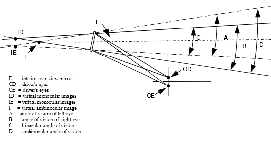
Figure 2
12.3. "Type of vehicle as regards indirect vision" means motor vehicles which are identical in respect of the following basic features:
12.3.1. Type of device for indirect vision;
12.3.2. The bodywork features which reduce the field of vision;
12.3.3. The coordinates of point R;
12.3.4. The prescribed positions, and type-approval markings of compulsory and (if fitted) optional devices for indirect vision.
12.4. "Vehicles of categories M1, M2, M3, N1, N2 and N3" means those defined in the Consolidated Resolution on the Construction of Vehicles (R.E.3), Annex 7 (document TRANS/WP.29/78/Rev.1/Amend.2).
12.5. "Unladen kerb mass" (MK) (kg) means the mass of the vehicle in running order, unoccupied and unladen but with the addition of 75 kg for the mass of the driver, the mass of fuel corresponding to 90 per cent of the capacity of the fuel tank specified by the manufacturer, and the masses of coolant, lubricant, tools and spare wheel, if any.
12.6. "Forward control" means a configuration in which more than half of the engine length is rearward of the foremost point of the windshield base and the steering wheel hub in the forward quarter of the vehicle length.
13. APPLICATION FOR APPROVAL
13.1. The application for approval of a vehicle type with regard to the installation of devices for indirect vision shall be submitted by the vehicle manufacturer or by his duly accredited representative.
13.2. A model of information document is shown in Annex 2.
13.3. A vehicle representative of the vehicle type to be approved shall be submitted to the technical service responsible for conducting the approval tests.
13.4. The competent authority shall verify the existence of satisfactory arrangements for ensuring effective checks on conformity of production before type‑approval is granted.
14. APPROVAL
14.1. If the vehicle type submitted for approval in accordance with paragraph 13. above meets the requirements of paragraph 15. of this Regulation, approval shall be granted.
14.2. An approval number shall be assigned to each type approved. Its first two digits (at present 02) shall indicate the series of amendments incorporating the most recent or technical amendments made to the Regulation at the time of issue of the approval. The same Contracting Party shall not assign the same number to another vehicle type.
14.3. Notice of approval or of refusal or of extension or withdrawal of approval of a vehicle type pursuant to this Regulation shall be communicated to the Parties to the Agreement which apply this Regulation by means of a form conforming to the model in Annex 4 to this Regulation.
15. REQUIREMENTS
15.1. GENERAL
15.1.1. (reserved)
15.1.2. Mirrors and other devices for indirect vision must be fitted in such a way that the mirror or other device does not move so as significantly to change the field of vision as measured or vibrate to an extent which would cause the driver to misinterpret the nature of the image perceived.
15.1.3. The conditions laid down in paragraph 15.1.2. must be maintained when the vehicle is moving at speeds of up to 80 per cent of its maximum design speed, but not exceeding 150 km/h.
15.1.4. The fields of vision defined below shall be established using ambinocular vision, the eyes being at the "driver's ocular points" as defined in paragraph 12.1. The fields of vision shall be determined when the vehicle is unladen in the condition described in paragraph 12.5. They shall be established through windows which have a total light transmission factor of at least 70 per cent measured normal to the surface.
15.2. MIRRORS
15.2.1. Number
15.2.1.1. Minimum number of compulsory mirrors
15.2.1.1.1. The fields of vision prescribed in paragraph 15.2.4. shall be obtained from the minimum number on mandatory mirrors set out in the following table. Where the presence of a mirror is not requested on a mandatory base, this means that no other system for indirect vision can be requested on a mandatory base.
Vehicle category | Interior mirror | Exterior mirrors |
Interior mirror Class I | Main mirror (large)
Class II | Main mirror (small) Class III | | Close-proximity mirror Class V | |
M1 | Compulsory Unless a mirror would not provide rearward vision (as defined in paragraph 15.2.4.1.) Optional If the mirror does not provide rearward vision | Optional | Compulsory 1 on the driver's side and 1 on the passenger's side Class II mirrors may be fitted as an alternative. | Optional
1 on the driver's side and / or 1 on the passenger's side | Optional
1 on the driver's side and 1 on the passenger's side (both must be fitted at least 2 m above the ground) | Optional
(must be fitted at least 2 m above the ground) |
M2 | Optional (no requirements for the field of view) | Compulsory 1 on the driver's side and
1 on the passenger's side | | Optional
1 on the driver's side and / or 1 on the passenger's side | Optional
1 on the driver's side and
1 on the passenger's side (both must be fitted at least 2 m above the ground) | Optional
(must be fitted at least 2 m above the ground) |
M3 | Optional (no requirementsfor the field of view) | Compulsory
1 on the driver's side and
1 on the passenger's side | Not permitted | Optional
1 on the driver's side and / or 1 on the passenger's side | Optional
1 on the driver's side and
1 on the passenger's side
(both must be fitted at least 2 m above the ground) | Optional (must be fitted at least 2 m above the ground) |
N1 | Compulsory Unless a mirror would not provide rearward vision
(as defined in paragraph 15.2.4.1.)
Optional If the mirror does not provide rearward vision | Optional
| Compulsory 1 on the driver's side and
1 on the passenger's side
Class II mirrors may be fitted as an alternative. | Optional
1 on the driver's side and / or 1 on the passenger's side | Optional
1 on the driver's side and
1 on the passenger's side
(both must be fitted at least 2 m above the ground) | Optional (must be fitted at least 2 m above the ground) |
N2 7,5 t | Optional(no requirements for the field of view) | Compulsory
1 on the driver's side and 1 on the passenger's side | Not permitted | Optional
1 on the driver's side and
1 on the passenger's side | Optional
1 on the passenger's side
1 on Driver's side
(both must be fitted at least 2 m above the ground) | Optional
1 front mirror
(must be fitted at least 2 m above the ground) |
N2 > 7,5 t | Optional (no requirementsfor the field of view) | Compulsory | Not permitted | Compulsory
1 on the driver's side and
1 on the passenger's side | Compulsory, see paragraph 15.2.2.7. and 15.2.4.5.5) 1 on the passenger's side Optional 1 on Driver's side (both must be fitted at least 2 m above the ground) | Compulsory, see paragraph 15.2.1.1.2
1. front mirror
(must be fitted at least 2 m above the ground) |
N3 | Optional (no requirementsfor the field of view) | Compulsory | Not permitted | Compulsory
1 on the driver's side and
1 on the passenger's side | Compulsory, see paragraph 15.2.2.7. and 15.2.4.5.5) 1 on the passenger's side Optional
1 on driver's side (both must be fitted at least 2 m above the ground) | Compulsory, see paragraph 15.2.1.1.2 1. front mirror
(must be fitted at least 2 m above the ground) |
15.2.1.1.2. In case the described field of vision of a front mirror prescribed in paragraph 15.2.4.6. can be obtained by another device for indirect vision that is approved according to paragraph 6.2. and that is installed according to paragraph 15., this device can be used instead of a mirror.
In case a camera/ monitor device is used the monitor must exclusively show the field of vision prescribed in paragraph 15.2.4.6. while the vehicle is moving forward with a speed up to 30 km/h.
In case the vehicle is moving with higher speed or moving backwards the monitor can be used to display the field of vision of other cameras mounted to the vehicle.
15.2.1.1.3. Motor vehicles having less than four wheels fitted with bodywork which partly or wholly encloses the driver shall be equipped:
either with an interior rear‑view mirror of Class I and an exterior rear‑view mirror of Class II or Class III, which shall be fitted to the drivers side of the vehicle,
or with two exterior rear‑view mirrors of Class II or Class III, one at each side of the vehicle.
The provisions of paragraph 15.2.4. below are not applicable to the above‑mentioned vehicles.
15.2.1.2. The provisions of this Regulation do not apply to the surveillance mirrors defined in paragraph 2.1.1.3. Nevertheless, the exterior surveillance mirrors must be mounted at least 2 m above the ground when the vehicle is under a load corresponding to its maximum technical permissible mass.
15.2.2. Position
15.2.2.1. Mirrors must be so placed that the driver, when sitting on the driving seat in a normal driving position, has a clear view of the road to the rear, side(s) or front of the vehicle.
15.2.2.2. Exterior mirrors shall be visible through the side windows or through the portion of the windscreen that is swept by the windscreen wiper. Nevertheless, for design reasons, this last provision (i.e. the provisions relating the cleaned part of the windscreen) shall not apply to:
exterior mirrors on the passenger side of vehicles of categories M2 and M3;
Class VI mirrors.
15.2.2.3. In the case of any vehicle, which is in chassis/cab form when the field of vision is measured, the minimum and maximum body widths shall be stated by the manufacturer and, if necessary, simulated by dummy headboards. All vehicles and mirror configurations taken into consideration during the tests shall be shown on the type-approval certificate for a vehicle with regard to the installation of mirrors (see Annex 4).
15.2.2.4. The prescribed exterior mirror on the driver’s side of the vehicle must be so located that an angle of not more than 55° is formed between the vertical longitudinal median plane of the vehicle and the vertical plane passing through the centre of the mirror and through the centre of the straight line 65 mm long which joins the driver's two ocular points.
15.2.2.5. Mirrors must not project beyond the external bodywork of the vehicle substantially more than is necessary to comply with the requirements concerning fields of vision laid down in paragraph 15.2.4.
15.2.2.6. Where the lower edge of an exterior mirror is less than 2 m above the ground when the vehicle is loaded to its technically permissible maximum laden mass, this mirror must not project more than 250 mm beyond the overall width of the vehicle measured without mirrors.
15.2.2.7. Class V and Class VI mirrors shall be mounted on vehicles in such a way that, regardless of their position after adjustment, no part of these mirrors or their holders is less than 2 m from the ground when the vehicle is under a load corresponding to its technically permissible maximum laden mass.
These mirrors shall not, however, be mounted on vehicles the cab height of which is such as to prevent compliance with this requirement. In this case an other device for indirect vision is not requested.
15.2.2.8. Subject to the requirements of paragraphs 15.2.2.5., 15.2.2.6. and 15.2.2.7., mirrors may project beyond the permissible maximum widths of vehicles.
15.2.3. Adjustment
15.2.3.1. The interior mirror must be capable of being adjusted by the driver from his driving position.
15.2.3.2. The exterior mirror situated on the driver's side must be capable of being adjusted from inside the vehicle while the door is closed, although the window may be open. The mirror may, however, be locked in position from the outside.
15.2.3.3. The requirements of paragraph 15.2.3.2. do not apply to exterior mirrors which, after having been knocked out of alignment, can be returned to their former position without the need for adjustment.
15.2.4. Fields of vision
15.2.4.1. Interior rear-view mirror (Class I)
The field of vision must be such that the driver can see at least a 20 m wide, flat, horizontal portion of the road centred on the vertical longitudinal median plane of the vehicle and extending from 60 m behind the driver’s ocular points (Figure 3) to the horizon.

Figure 3: Field of vision of Class I mirror
15.2.4.2. Main exterior rear-view mirrors Class II
15.2.4.2.1. Exterior rear-view mirror on the driver's side
The field of vision must be such that the driver can see at least a 5 m wide, flat, horizontal portion of the road, which is bounded by a plane which is parallel to the median longitudinal vertical plane and passing through the outermost point of the vehicle on the driver's side of the vehicle and extends from 30 m behind the driver's ocular points to the horizon.
In addition, the road must be visible to the driver over a width of 1 m, which is bounded by a plane parallel to the median longitudinal vertical plane and passing through the outermost point of the vehicle starting from a point 4 m behind the vertical plane passing through the driver's ocular points (see Figure 4).
15.2.4.2.2. Exterior rear-view mirror on the passenger's side
The field of vision must be such that the driver can see at least a 5 m wide, flat, horizontal portion of the road, which is bounded on the passenger's side by a plane parallel to the median longitudinal vertical plane of the vehicle and passing through the outermost point of the vehicle on the passenger's side and which extends from 30 m behind the drivers ocular points to the horizon.
In addition, the road must be visible to the driver over a width of 1 m, which is bounded by a plane parallel to the median longitudinal vertical plane and passing through the outermost point of the vehicle starting from a point 4 m behind the vertical plane passing through the driver's ocular points (see Figure 4).

Figure 4: Field of vision of Class II mirrors
15.2.4.3. Main exterior rear-view mirrors Class III
15.2.4.3.1. Exterior rear-view mirror on the driver’s side
The field of vision must be such that the driver can see at least a 4 m wide, flat, horizontal portion of the road, which is bounded by a plane parallel to the median longitudinal vertical plane and passing through the outermost point of the vehicle on the driver’s side of the vehicle and extends from 20 m behind the driver’s ocular points to the horizon (see Figure 5).
In addition, the road must be visible to the driver over a width of 1 m, which is bounded by a plane parallel to the median longitudinal vertical plane and passing through the outermost point of the vehicle starting from a point 4 m behind the vertical plane passing through the driver’s ocular points.
15.2.4.3.2. Exterior rear-view mirror on the passenger’s side
The field of vision must be such that the driver can see at least a 4 m wide flat, horizontal portion of the road which is bounded by a plane parallel to the median longitudinal vertical plane passing through the outermost point of the vehicle on the passenger’s side and which extends from 20 m behind the driver’s ocular points to the horizon (see Figure 5).
In addition, the road must be visible to the driver over a width of 1 m, which is bounded by a plane parallel to the median longitudinal vertical plane and passing through the outermost point of the vehicle starting from a point 4 m behind the vertical plane passing through the driver’s ocular points.

Figure 5: Field of vision of Class III mirrors
15.2.4.4. "Wide-angle" exterior mirror (Class IV)
15.2.4.4.1. "Wide-angle" exterior mirror on the driver’s side
The field of vision must be such that the driver can see at least a 15 m wide, flat, horizontal portion of the road, which is bounded by a plane parallel to the median longitudinal vertical plane of the vehicle and passing through the outermost point of the vehicle on the driver’s side and which extends from at least 10 m to 25 m behind the driver’s ocular points.
In addition, the road must be visible to the driver over a width of 4.5 m, which is bounded by a plane parallel to the median longitudinal vertical plane and passing through the outermost point of the vehicle starting from a point 1.5 m behind the vertical plane passing through the driver’s ocular points (see Figure 6).
15.2.4.4.2. "Wide-angle" exterior mirror on the passenger’s side
The field of vision must be such that the driver can see at least a 15 m wide, flat, horizontal portion of the road, which is bounded by a plane parallel to the median longitudinal vertical plane of the vehicle and passing through the outermost point of the vehicle on the passenger’s side and which extends from at least 10 m to 25 m behind the driver’s ocular points.
In addition, the road must be visible to the driver over a width of 4.5 m, which is bounded by a plane parallel to the median longitudinal vertical plane and passing through the outermost point of the vehicle starting from a point 1.5 m behind the vertical plane passing through the driver’s ocular points (see Figure 6).

Figure 6: Field of vision of Class IV wide-angle mirrors
15.2.4.5. "Close-proximity" exterior mirror (Class V)
The field of vision must be such that the driver can see a flat horizontal portion of the road along the side of the vehicle, bounded by the following vertical planes (see Figures 7a and 7b):
15.2.4.5.1. The plane parallel to the median longitudinal vertical plane of the vehicle which passes through the outermost point of the vehicle cab on the passenger’s side;
15.2.4.5.2. in the transverse direction, the parallel plane passing at a distance of 2 m in front of the plane mentioned in paragraph 15.2.4.5.1.
15.2.4.5.3. to the rear, the plane parallel to the vertical plane passing through the driver’s ocular points and situated at a distance of 1.75 m behind that plane;
15.2.4.5.4. to the front, the plane parallel to the vertical plane passing through the driver’s ocular points and situated at a distance of 1 m in front of that plane. If the vertical transverse plane passing through the leading edge of the vehicle bumper is less than 1 m in front of the vertical plane passing through the driver’s ocular points, the field of vision shall be limited to that plane.
15.2.4.5.5. In case the field of vision described in Figures 7a and 7b can be perceived through the combination of the field of vision from a Class IV wide-angle mirror and that of a Class VI front mirror, the installation of a Class V close proximity mirror is not compulsory.


Figures 7a and 7b: Field of vision of Class V close-proximity mirror
15.2.4.6. Front mirror (Class VI)
15.2.4.6.1. The field of vision must be such that the driver can see at least a flat horizontal portion of the road, which is bounded by:
- One traverse vertical plane through the outermost point of the front of the vehicle-cab,
- one traverse vertical plane 2,000 mm in front of the vehicle,
- one longitudinal vertical plane parallel to the longitudinal vertical median plane going though the outermost side of the vehicle at the driver’s side and
- one longitudinal vertical plane parallel to the longitudinal vertical median plane 2,000 mm outside the outermost side of the vehicle opposite to the driver’s side.
The front of this field of vision opposite to the driver’s side may be rounded off with a radius of 2,000 mm (see Figure 8).
The provisions for front mirrors are compulsory for forward controlled (as defined in paragraph 12.6.) vehicles of categories N2 > 7.5 t and N3.
If vehicles of these categories with other construction characteristics regarding the bodywork cannot fulfil the requirements by using a front mirror, a camera/monitor device shall be used. If either of these options do not provide the adequate field of vision then any other device for indirect vision shall be used. This device must be able to detect an object of 50 cm height and with a diameter of 30 cm within the field defined in Figure 8.

Figure 8: Field of vision of Class VI front mirror
15.2.4.6.2. However, if the driver can see, taking into account the obstructions by the A‑pillars, a straight line 300 mm in front of the vehicle at a height of 1,200 mm above the road surface and which is situated between a longitudinal vertical plane parallel to the longitudinal vertical median plane going through the outermost side of the vehicle at the driver’s side and a longitudinal vertical plane parallel to the longitudinal vertical median plane 900 mm outside the outermost side of the vehicle opposite to the driver’s side, a front mirror of Class VI is not mandatory.
15.2.4.7. In the case of mirrors consisting of several reflecting surfaces which are either of different curvature or make an angle with each other, at least one of the reflecting surfaces must provide the field of vision and have the dimensions (paragraph 6.1.2.1.2.2.) specified for the class to which they belong.
15.2.4.8. Obstructions
15.2.4.8.1. Interior rear-view mirror (Class I)
The field of vision may be reduced by the presence of headrest and devices such as, in particular, sun visors, rear windscreen wipers, heating elements and stop lamp of category S3 or by components of bodywork such as window columns of rear split doors, provided that all these devices together do not obscure more than 15 per cent of the prescribed field of vision when projected onto a vertical plane perpendicular to the longitudinal median plane of the vehicle. The degree of obstruction shall be measured with the headrests adjusted to their lowest possible position and with the sun visors folded back.
15.2.4.8.2. Exterior mirrors (Classes II, III, IV, V and VI)
In the fields of vision specified above, obstruction due to the bodywork and some of its components, such as mirrors, door handles, outline marker lights, direction indicators and rear bumpers, as well as reflective-surface cleaning components, shall not be taken into account if they are responsible for a total obstruction of less than 10 per cent of the specified field of vision.
15.2.4.9. Test procedure
The field of vision shall be determined by placing powerful light sources at the ocular points and examining the light reflected on the vertical monitoring screen. Other equivalent methods may be used.
15.3. DEVICES FOR INDIRECT VISION OTHER THAN MIRRORS
15.3.1. A device for indirect vision shall give such performances that a critical object can be observed within the described field of vision, taking into account the critical perception.
15.3.2. Obstruction of the driver’s direct view caused by the installation of a device for indirect vision shall be restricted to a minimum.
15.3.3. For the determination of the detection distance in case of camera-monitor devices for indirect vision, the procedure of Annex 10 shall be applied.
15.3.4. Installation requirements for the monitor
The viewing direction of the monitor shall roughly be the same direction as the one for the main mirror.
15.3.5. Vehicles of category M2 and M3 and complete or completed vehicles of categories N2 7.5 t and N3 having a special bodywork for refuse collection may be equipped on the rear part of their bodywork with a device for indirect vision other than a mirror in order to ensure the following field of vision.
15.3.5.1. The field of vision (Figure 9) must be such that the driver can see at least a flat horizontal portion of the road, which is bounded by :
- a vertical plane aligned on the furthest rear point of the complete vehicle and perpendicular to the longitudinal vertical median plane of the vehicle;
- a vertical plane which is parallel to and positioned 2,000 mm to the rear of the previous plane (with respect to the rear of the vehicle);
- two longitudinal vertical planes defined at the outermost sides of the vehicle and which are parallel to the longitudinal vertical median plane of the vehicle.
15.3.5.2. If vehicles of these categories cannot fulfil the requirements of paragraph 15.3.5 1. by using a camera/monitor device, other devices for indirect vision can be used. In this case the device must be able to detect an object of 50 cm height and with a diameter of 30 cm within the field defined in paragraph 15.3.5.1.

Figure 9 : Field of vision of rear devices for indirect vision
16. MODIFICATIONS OF THE VEHICLE TYPE AND EXTENSION OF APPROVAL
16.1. Every modification of the vehicle type shall be notified to the administrative department which approved the vehicle type. The department may then either:
16.1.1. Consider that the modifications made are unlikely to have an appreciable adverse effect, and that in any case the vehicle still complies with the requirements; or
16.1.2. Require a further test report from the technical service responsible for conducting the tests.
16.2. Confirmation or refusal of approval, specifying the alterations, shall be communicated to the Parties to the Agreement which apply this Regulation by means of a form conforming to the model in Annex 4 to this Regulation.
16.3. The competent authority issuing the extension of approval shall assign a series number to each communication form drawn up for such an extension.
17. CONFORMITY OF PRODUCTION
17.1 The conformity of production procedure shall comply with those set out in the Agreement, Appendix 2, (E/ECE/324-E/ECE/TRANS/505/Rev.2).
17.2 Every vehicle approved under this Regulation shall be so manufactured as to conform to the type approved by meeting the requirements set out in paragraph 15. above.
18. PENALTIES FOR NON‑CONFORMITY OF PRODUCTION
18.1. The approval granted in respect of a vehicle type pursuant to this Regulation may be withdrawn if the requirement laid down in paragraph 17.1. above is not complied with or if the vehicle fails to pass the checks prescribed in paragraph 17.2. above.
18.2. If a Party to the Agreement which applies this Regulation withdraws an approval it has previously granted, it shall forthwith so notify the other Contracting Parties applying this Regulation by means of a copy of the approval form bearing at the end, in large letters, the signed and dated annotation "APPROVAL WITHDRAWN".
19. PRODUCTION DEFINITELY DISCONTINUED
If the holder of the approval completely ceases to manufacture a type of vehicle approved in accordance with this Regulation, he shall so inform the authority which granted the approval. Upon receiving the relevant communication, that authority shall inform thereof the other Parties to the Agreement applying this Regulation by means of a copy of the approval form bearing at the end, in large letters, the signed and dated annotation "PRODUCTION DISCONTINUED".
20. NAMES AND ADDRESSES OF TECHNICAL SERVICES RESPONSIBLE FOR CONDUCTING APPROVAL TESTS, AND OF ADMINISTRATIVE DEPARTMENTS
The Parties to the Agreement applying this Regulation shall communicate to the United Nations Secretariat the names and addresses of the technical services responsible for conducting approval tests and of the administrative departments which grant approval and to which forms certifying approval or refusal or extension or withdrawal of approval, issued in other countries, are to be sent.
21. TRANSITIONAL PROVISIONS
21.1. As from the official date of entry into force of the 02 series of amendments to this Regulation, no Contracting Party applying this Regulation shall refuse an application for approval under this Regulation as amended by the 02 series of amendments.
21.2. As from 26 January 2006, Contracting Parties applying this Regulation shall grant approvals to a type of vehicle with regard to the installation of devices for indirect vision only if the type of vehicle meets the requirements of this Regulation as amended by the 02 series of amendments. However, this date shall be postponed by 12 months as regards the requirements concerning the installation of a Class VI front mirror.
21.3. As from 26 January 2006, Contracting Parties applying this Regulation shall grant approvals to a type of devices for indirect vision only if the type meets the requirements of this Regulation as amended by the 02 series of amendments.
21.4. As from 26 January 2010 for vehicles of category M1 and N1 and 26 January 2007 for vehicles of other categories, Contracting Parties applying this Regulation may refuse to recognize approvals of a type of vehicle which have not been granted in accordance with the 02 series of amendments to this Regulation.
21.5. As from 26 January 2010 for vehicles of category M1 and N1 and from 26 January 2007 for vehicles of other categories, Contracting Parties applying this Regulation may refuse to recognize approvals of a device for indirect vision which have not been granted in accordance with the 02 series of amendments to this Regulation.
21.6. Approvals which were granted to rear‑view mirrors of Classes I or III pursuant to this Regulation in its original form (00 series) or modified by the 01 series of amendments before the date of entry into force of this series of amendments shall remain valid.
21.7. The provisions of this Regulation shall not prohibit the approval of a type of vehicle with regard to the mounting of rear-view mirrors pursuant to this Regulation as modified by the 02 series of amendments, if all or part of the rear‑view mirrors of Classes I or III, with which it is fitted, bear the approval mark prescribed by the original version (00 or 01series) of this Regulation.
21.8. Notwithstanding the provisions of paragraphs 21.3. and 21.5. above, for the purpose of replacement parts Contracting Parties applying this Regulation shall continue to grant approvals according to the 01 series of amendments to this Regulation, to devices for indirect vision for use on vehicle types which have been approved before the date mentioned in paragraph 21.2. pursuant to the 01 series of amendments of Regulation No. 46, and, where applicable, subsequent extensions to these approvals.
Annex 1
INFORMATION DOCUMENT
FOR TYPE-APPROVAL OF A DEVICE FOR INDIRECT VISION
The following information, if applicable, shall be supplied in triplicate and must include a list of contents.
Any drawings shall be supplied in appropriate scale and in sufficient detail on size A4 paper or on a folder of A4 format.
Photographs, if any, shall show sufficient detail.
1. Make (trade name of manufacturer): .......................................
2. Type and general commercial description(s): ................................
3. Means of identification of the type, if indicated on the device:...................
4. Category of vehicle for which the device is intended:..........................
5. Name and address of manufacturer: .......................................
6. Location and method of affixing of the approval mark: ........................
7. Address(es) of assembly plant(s): .........................................
8. Mirrors (state for each mirror):............................................
8.1. Variant ..............................................................
8.2. Drawing(s) for the identification of the mirror: ...............................
8.3. Details of the method of attachment: .......................................
9. Devices for indirect vision other than mirrors:................................
9.1. Type and characteristics (such as a complete description of the device): ...........
9.1.1. In the case of camera-monitor device, the detection distance (mm), contrast, luminance range, glare correction, display performance (black and white/colour) image repetition frequency, luminance reach of the monitor:
9.2. sufficiently detailed drawings to identify the complete device including installation instructions; the position for the type-approval mark has to be indicated on the drawings:
Annex 2
INFORMATION DOCUMENT
FOR TYPE-APPROVAL OF A VEHICLE WITH RESPECT TO
THE INSTALLATION OF DEVICES FOR INDIRECT VISION
The following information, if applicable, shall be supplied in triplicate and include a list of contents.
Any drawings shall be supplied in appropriate scale and in sufficient detail on size A4 paper or on a folder of A4 format.
Photographs, if any, shall show sufficient detail.
GENERAL
1. Make (trade name of manufacturer):.......................................
2. Type and general commercial description(s):................................
3. Means of identification of type, if marked on the vehicle (b):....................
4. Location of that marking:................................................
5. Category of vehicle (c):.................................................
6. Name and address of manufacturer:........................................
7. Address(es) of assembly plant(s):.........................................
GENERAL CONSTRUCTION CHARACTERISTICS OF THE VEHICLE
8. Photograph(s) and/or drawing(s) of a representative vehicle:....................
9. Driving cab (forward control or bonneted) :...............................
10. Driving position: left/right 1/ ............................................
10.1. The vehicle is equipped to be driven in right-hand/left hand traffic 1/
11. Range of vehicle dimensions (overall):.....................................
11.1 For chassis without bodywork
11.1.1. Width: ...........................................................
11.1.1.1. Maximum permissible width: ............................................
11.1.1.2. Minimum permissible width: ............................................
11.2. For chassis with bodywork: ..............................................
11.2.1. Width 1/ .............................................................
12.1. Devices for indirect vision
12.1.1.1. Drawing(s) showing the position of the mirror relative to the vehicle structure: .....
12.1.1.2. Details of the method of attachment including that part of the vehicle structure to which it is attached: ………………
12.1.1.3. Optional equipment which may affect the rearward field of vision: ...............
12.1.1.4 A brief description of the electronic components (if any) of the adjustment
device: ..............................................................
12.1.2. Devices for indirect vision other than mirrors: ...............................
12.1.2.1. Sufficiently detailed drawings with the installation instructions:..................
Annex 3
COMMUNICATION
(Maximum format: A4 (210 x 297 mm))


concerning: APPROVAL GRANTED
APPROVAL EXTENDED
APPROVAL REFUSED
APPROVAL WITHDRAWN
PRODUCTION DEFINITELY DISCONTINUED
of a type of device for indirect vision to Regulation No. 46
Approval No. ..... Extension No. .....
1. Trade name or mark of device: ...........................................
2. Manufacturer’s name for the type of device:.................................
3. Manufacturer’s name and address:.........................................
4. If applicable, name and address of Manufacturer's representative:................
5. Submitted for approval on:...............................................
6. Technical service responsible for conducting approval tests:....................
7. Date of report issued by that service...............................................
8. Number of report issued by that service.....................................
Identification of the device: mirror, camera/monitor, other device 2/
Device for indirect vision of Class I, II, III, IV, V, VI, S 2/
Symbol as defined in paragraph 6.1.3.1.1. of this Regulation: yes/no 2/
10. Position of the approval mark:............................................
11. Reason(s) for extension (if applicable):.....................................
12. Approval granted/refused/extended/withdrawn: 2/
13. Place:...............................................................
14. Date:................................................................
15. Signature:............................................................
16. The list of documents deposited with the Administrative Service which has granted approval is annexed to this communication and may be obtained on request.
Annex 4
COMMUNICATION
(Maximum format: A4 (210 x 297 mm))

concerning: APPROVAL GRANTED
APPROVAL EXTENDED
APPROVAL REFUSED
APPROVAL WITHDRAWN
PRODUCTION DEFINITELY DISCONTINUED
of a type of vehicle with regard to the mounting of devices for indirect vision pursuant to Regulation No. 46
Approval number:…………. Extension No.: ……………
1. Make (trade name of manufacturer): .........................................
2. Type and general commercial description(s)...................................
3. Means of identification of type, if marked on the vehicle:.........................
3.1. Location of that marking:..................................................
4. Category of vehicle: (M1, M2, M3, N1, N2 7.5t, N2 > 7.5t, N3) 2/
5. Name and address of manufacturer:..........................................
6. Address(es) of the production plant(s)........................................
7. Additional information: (where applicable): See appendix
8. Technical service responsible for carrying out the tests:..........................
9. Date of test report:.......................................................
10. Number of test report:....................................................
11. Remarks: (if any): See appendix
12. Place:.................................................................
13. Date: .................................................................
14 Signature:..............................................................
15. The index to the information package lodged with the approval authority, which may be obtained on request is attached.
Appendix to type-approval communication form No. ……concerning the type-approval of a vehicle with regard to the mounting of devices for indirect vision under Regulation No. 46
1. Trade name or mark of mirrors and supplementary devices for indirect vision and component type-approval number: …………………………………………………
2. Class(es) of mirrors and devices for indirect vision (I, II, III, IV, V, VI, S) 2/)
3. Extension of type approval of the vehicle to cover the following device for indirect vision
………………………………………………………………………………………
4. Data for identification of the R point of the driver’s seating position:
………………………………………………………………………………………
5. Maximum and minimum bodywork width in respect of which the mirror and the devices for indirect vision has been granted type-approval (in the case of chassis/cab referred to in paragraph 15.2.2.3.)
6. The following documents, bearing the type-approval number shown above, are annexed to this certificate:
- drawings showing the mounting of the devices for indirect vision
- drawings and plans showing the mounting position and characteristics of the part of the structure where the devices for indirect vision are mounted.
7. Remarks: (e.g. valid for right hand/left hand traffic 2/ )
Annex 5
ARRANGEMENT OF APPROVAL MARK OF A DEVICE FOR INDIRECT VISION
(See paragraph 5.4. of the Regulation)
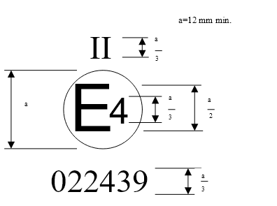
The above approval mark affixed to a device for indirect vision indicates that the mirror is a rear‑view mirror, of Class II, which has been approved in the Netherlands (E 4) pursuant to Regulation No. 46 and under approval number 022439. The first two digits of the approval number indicate that Regulation No. 46 already included the 02 series of amendments when the approval was granted.
______________
Note: The approval number and the additional symbol must be placed close to the circle and either above or below the "E" or to the left or right of that letter. The digits of the approval number must be on the same side of the "E" and point in the same direction. The additional symbol must be directly opposite the approval number. The use of Roman numerals as approval numbers should be avoided so as to prevent any confusion with other symbols.
Annex 6
TEST METHOD FOR DETERMINING REFLECTIVITY
1. DEFINITIONS
1.1. CIE standard illuminate A 1/: Colorimetric illuminate, respecting the full radiator at T68 = 2 855.6 K.
1.1.2. CIE standard source A 1/: Gas-filled tungsten filament lamp operating at a correlated colour temperature of T68 = 2,855.6 K.
1.1.3. CIE 1931 standard colorimetric observer 1/: Receptor of radiation whose colorimetric characteristics correspond to the spectral tristimulus values  (see table).
1.1.4. CIE spectral tristimulus values 1/: Tristimulus values of the spectral components of an equi energy spectrum in the CIE (XYZ) system.
1.1.5. Photopic vision : Vision by the normal eye when it is adapted to levels of luminance of at least several cd/m2.
2. APPARATUS
2.1. General
The apparatus shall consist of a light source, a holder for the test sample, a receiver unit with a photodetector and an indicating meter (see Figure 1), and means of eliminating the effects of extraneous light.
The receiver may incorporate a light-integrating sphere to facilitate measuring the reflectance of non-flat (convex) mirrors (see Figure 2).
2.2. Spectral characteristics of light source and receiver
The light source shall consist of a CIE standard source A and associated optics to provide a near-collimated light beam. A voltage stabiliser is recommended in order to maintain a fixed lamp voltage during instrument operation.
The receiver shall have a photodetector with a spectral response proportional to the photopic luminosity function of the CIE (1931) standard colorimetric observer (see table). Any other combination of illuminate-filter-receptor giving the overall equivalent of CIE standard illuminate A and photopic vision may be used. When an integrating sphere is used in the receiver, the interior surface of the sphere shall be coated with a matt (diffusive) spectrally non-selective white coating.
2.3. Geometrical conditions
The angle of the incident beam ( ) should preferably be 0.44 ± 0.09 rad (25 ± 5°) from the perpendicular to the test surface and shall not exceed the upper limit of the tolerance (i.e. 0.53 rad or 30°). The axis of the receptor shall make an angle (
 ) with this perpendicular equal to that of the incident beam (see Figure 1). The incident beam upon arrival at the test surface shall have a diameter of not less than 13 mm (0.5 in.). The reflected beam shall not be wider than the sensitive area of the photodetector, shall not cover less than 50 per cent of such area, and as nearly as possible shall cover the same area segment as used during instrument calibration.
When an integrating sphere is used in the receiver section, the sphere shall have a minimum diameter of 127 mm (5 in.). The sample and incident beam apertures in the sphere wall shall be of such a size as to admit the entire incident and reflected light beams. The photodetector shall be so located as not to receive direct light from either the incident or the reflected beam.
2.4. Electrical characteristics of the photodetector-indicator unit
The photodetector output as read on the indicating meter shall be a linear function of the light intensity of the photosensitive area. Means (electrical and/or optical) shall be provided to facilitate zeroing and calibration adjustments. Such means shall not affect the linearity or the spectral characteristics of the instrument. The accuracy of the receptor indicator unit shall be within ± 2 per cent of full scale, or ± 10 per cent of the magnitude of the reading, whichever is the smaller.
2.5. Sample holder
The mechanism shall be capable of locating the test sample so that the axes of the source arm and receptor intersect at the reflecting surface. The reflecting surface may lie within or at either face of the mirror sample, depending on whether it is a first surface, second surface or prismatic "flip" type mirror.
3. PROCEDURE
3.1. Direct calibration method
In the direct calibration method, air is used as the reference standard. This method is applicable for those instruments, which are so constructed as to permit calibration at the 100 per cent point by swinging the receiver to a position directly on the axis of the light source (see Figure 1).
It may be desired in some cases (such as when measuring low-reflectivity surfaces) to use an intermediate calibration point (between 0 and 100 per cent on the scale) with this method. In these cases, a neutral density filter of known transmittance shall be inserted in the optical path, and the calibration control shall then be adjusted until the meter reads the percentage transmission of the neutral density filter. This filter shall be removed before reflectivity measurements are performed.
3.2. Indirect calibration method
The indirect calibration method is applicable in the case of instruments with fixed source and receiver geometry. A properly calibrated and maintained reflectance standard is required. This reference standard should preferably be a flat mirror with a reflectance value as near as possible to that of the test samples.
3.3. Flat mirror measurement
The reflectance of flat mirror samples can be measured on instruments employing either the direct or the indirect calibration method. The reflectance value is read directly from the indicating meter.
3.4. Non-flat (convex) mirror measurement
Measurement of the reflectance of non-flat (convex) mirrors requires the use of instruments which incorporate an integrating sphere in the receiver unit (see Figure 2). If the instrument-indicating meter indicates ne divisions with a standard mirror of E per cent reflectance, then, with a mirror of unknown reflectance, nx divisions will correspond to a reflectance of X per cent, in accordance with the formula:

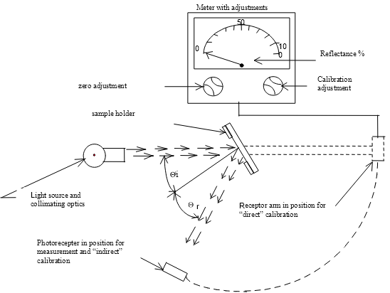
Figure 1: Generalised reflectometer showing experimental set-ups for the two calibration methods
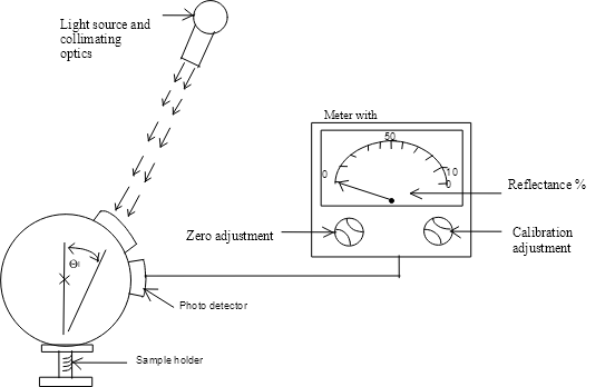
Figure 2: Generalised reflectometer, incorporating an integrating sphere in the receiver
SPECTRAL TRISTIMULUS VALUES FOR THE CIE 1931 STANDARD COLORMETRIC OBSERVER 2/
This table is taken from CIE publication 50 (45) (1970)

_____________
Example of device for measuring the reflection factor of spherical mirrors
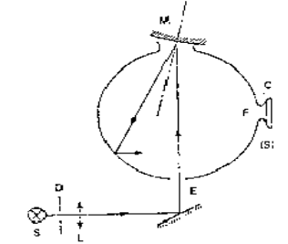
C = Receiver
D = Diaphragm
E = Window of entry
F = Window of measurement
L = Lens
M = Object window
S = Light source
(S) = Integrating sphere
Annex 7
PROCEDURE FOR DETERMINING THE RADIUS OF CURVATURE "r" OF THE
REFLECTING SURFACE OF A MIRROR
1. MEASUREMENT
1.1. Equipment
A "spherometer" similar to the one described in Figure 1 of this annex having the indicated distances between the tracing pin of the dial gauge and the fixed legs of the bar is used.
1.2. Measuring points
1.2.1. The principal radii of curvature shall be measured at three points situated as close as possible to positions at one-third, one-half and two-thirds of the distance along the arc of the reflecting surface passing through the centre of this surface and parallel to segment b, or of the arc passing through the centre of the reflecting surface which is perpendicular to it if this arc is the longer.
1.2.2. Where, owing to the size of the reflecting surface, it is impossible to obtain measurements in the directions defined in paragraph 2.1.1.5. of this Regulation, the technical services responsible for the tests may take measurements at the said point in two perpendicular directions as close as possible to those prescribed above.
2. CALCULATION OF THE RADIUS OF CURVATURE "r"
"r" expressed in mm is calculated from the formula:

where:
rp1 = the radius of curvature at the first measuring point,
rp2 = the radius of curvature at the second measuring point,
rp3 = the radius of curvature at the third measuring point.

| 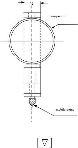
|
Figure 1: spherometer |
Annex 8
PROCEDURE FOR DETERMINING THE "H" POINT AND THE ACTUAL TORSO ANGLE
FOR SEATING POSITIONS IN MOTOR VEHICLES
1. PURPOSE
The procedure described in this annex is used to establish the "H" point location and the actual torso angle for one or several seating positions in a motor vehicle and to verify the relationship of measured data to design specifications given by the vehicle manufacturer. /
2. DEFINITIONS
For the purposes of this annex:
2.1. "Reference data" means one or several of the following characteristics of a seating position:
2.1.1. the "H" point and the "R" point and their relationship;
2.1.2. the actual torso angle and the design torso angle and their relationship.
2.2. "Three‑dimensional 'H' point machine" (3-D H machine) means the device used for the determination of "H" points and actual torso angles. This device is described in Appendix 1 to this annex.
2.3. "'H' point" means the pivot centre of the torso and thigh of the 3-D H machine installed in the vehicle seat in accordance with paragraph 4. below. The "H" point is located in the centre of the centreline of the device which is between the "H" point sight buttons on either side of the 3-D H machine. The "H" point corresponds theoretically to the "R" point (for tolerances see paragraph 3.2.2. below). Once determined in accordance with the procedure described in paragraph 4., the "H" point is considered fixed in relation to the seat‑cushion structure and to move with it when the seat is adjusted.
2.4.1.1. "'R' point" or "seating reference point" means a design point defined by a vehicle manufacturer for each seating position and established with respect to the three‑dimensional reference system;
2.5. "Torso‑line" means the centreline of the probe of the 3-D H machine with the probe in the fully rearward position.
2.6. "Actual torso angle" means the angle measured between a vertical line through the "H" point and the torso line using the back angle quadrant on the 3-D H machine. The actual torso angle corresponds theoretically to the design torso angle (for tolerances see paragraph 3.2.2. below).
2.7. "Design torso angle" means the angle measures between a vertical line through the "R" point and the torso line in a position which corresponds to the design position of the seat‑back established by the vehicle manufacturer.
2.8. "Centreplane of occupant" (C/LO) means the median plane of the 3-D H machine positioned in each designated seating position; it is represented by the co‑ordinate of the "H" point on the "Y" axis. For individual seats, the centreplane of the seat coincides with the centreplane of the occupant. For other seats, the centreplane of the occupant is specified by the manufacturer;
2.9. "Three‑dimensional reference system" means a system as described in Appendix 2 to this annex;
2.10. "Fiducial marks" are physical points (holes, surfaces, marks or indentations) on the vehicle body as defined by the manufacturer;
2.11. "Vehicle measuring attitude" means the position of the vehicle as defined by the co‑ordinates of fiducial marks in the three-dimensional reference system.
3. REQUIREMENTS
3.1. Data presentation
For each seating position where reference data are required in order to demonstrate compliance with the provisions of the present Regulation, all or an appropriate selection of the following data shall be presented in the form indicated in Appendix 3 to this annex:
3.1.1. the co‑ordinates of the "R" point relative to the three‑dimensional reference system;
3.1.2. the design torso angle;
3.1.3. all indications necessary to adjust the seat (if it is adjustable) to the measuring position set out in paragraph 4.3. below.
3.2. Relationship between measured data and design specifications
3.2.1. The co‑ordinates of the "H" point and the value of the actual torso angle obtained by the procedure set out in paragraph 4. below shall be compared, respectively, with the co‑ordinates of the "R" point and the value of the design torso angle indicated by the vehicle manufacturer.
3.2.2. The relative positions of the "R" point and the "H" point and the relationship between the design torso angle and the actual torso angle shall be considered satisfactory for the seating position in question if the "H" point, as defined by its co‑ordinates, lies within a square of 50 mm side length with horizontal and vertical sides whose diagonals intersect at the "R" point, and if the actual torso angle is within 5 degree of the design of the torso angle.
3.2.3. If these conditions are met, the "R" point and the design torso angle, shall be used to demonstrate compliance with the provisions of this Regulation.
3.2.4. If the "H" point or the actual torso angle does not satisfy the requirements of paragraph 3.2.2. above, the "H" point and the actual torso angle shall be determined twice more (three times in all). If the results of two of these three operations satisfy the requirements, the conditions of paragraph 3.2.3. above shall apply.
3.2.5. If the results of at least two of the three operations described in paragraph 3.2.4. above do not satisfy the requirements of paragraph 3.2.2. above, or if the verification cannot take place because the vehicle manufacturer has failed to supply information regarding the position of the "R" point or regarding the design torso angle, the centroid of the three measured points or the average of the three measured angles shall be used and be regarded as applicable in all cases where the "R" point or the design torso angle is referred to in this Regulation.
4. PROCEDURE FOR "H" POINT AND ACTUAL TORSO ANGLE DETERMINATION
4.1. The vehicle shall be preconditioned at the manufacturer's discretion, at a temperature of 20 + 10°C to ensure that the seat material reaches the room temperature. If the seat to be checked has never been sat upon, a 70 to 80 kg person or device shall sit on the seat twice for one minute to flex the cushion and back. At the manufacturer's request, all seat assemblies shall remain unloaded for a minimum period of 30 min prior to installation of the 3-D H machine.
4.2. The vehicle shall be at the measuring attitude defined in paragraph 2.11. above.
4.3. The seat, if it is adjustable, shall be adjusted first to the rearmost normal driving or riding position, as indicated by the vehicle manufacturer, taking into consideration only the longitudinal adjustment of the seat, excluding seat travel used for purposes other than normal driving or riding positions. Where other modes of seat adjustment exist (vertical, angular, seat-back, etc.) these will be then adjusted to the position specified by the vehicle manufacturer. For suspension seats, the vertical position shall be rigidly fixed corresponding to a normal driving position as specified by the manufacturer.
4.4. The area of the seating position contacted by the 3-D H machine shall be covered by a muslin cotton, of sufficient size and appropriate texture, described as a plain cotton fabric having 18.9 threads per/cm2 and weighing 0.228 kg/m2 or knitted or non‑woven fabric having equivalent characteristics.
If test is run on a seat outside the vehicle, the floor on which the seat is placed shall have the same essential characteristics / as the floor of the vehicle in which the seat is intended to be used.
4.5. Place the seat and back assembly of the 3-D H machine so that the centreplane of the occupant (C/LO) coincides with the centreplane of the 3-D H machine. At the manufacturer's request, the 3-D H machine may be moved inboard with respect to the C/LO if the 3-D H machine is located so far outboard that the seat edge will not permit levelling of the 3-D H machine.
4.6. Attach the foot and lower leg assemblies to the seat pan assembly, either individually or by using the T‑bar and lower leg assembly. A line through the "H" point sight buttons shall be parallel to the ground and perpendicular to the longitudinal centreplane of the seat.
4.7. Adjust the feet and leg positions of the 3-D H machine as follows:
4.7.1. Designated seating position: driver and outside front passenger
4.7.1.1. Both feet and leg assemblies shall be moved forward in such a way that the feet take up natural positions on the floor, between the operating pedals if necessary. Where possible the left foot shall be located approximately the same distance to the left of the centreplane of the 3-D H machine as the right foot is to the right. The spirit level verifying the transverse orientation of the 3-D H machine is brought to the horizontal by readjustment of the seat pan if necessary, or by adjusting the leg and foot assemblies towards the rear. The line passing through the "H" point sight buttons shall be maintained perpendicular to the longitudinal centreplane of the seat.
4.7.1.2. If the left leg cannot be kept parallel to the right leg and the left foot cannot be supported by the structure, move the left foot until it is supported. The alignment of the sight buttons shall be maintained.
4.7.2. Designated seating position: outboard rear
For rear seats or auxiliary seats, the legs are located as specified by the manufacturer. If the feet then rest on parts of the floor which are at different levels, the foot which first comes into contact with the front seat shall serve as a reference and the other foot shall be so arranged that the spirit level giving the transverse orientation of the seat of the device indicates the horizontal.
4.7.3. Other designated seating positions:
The general procedure indicated in paragraph 4.7.1. above shall be followed except that the feet shall be placed as specified by the vehicle manufacturer.
4.8. Apply lower leg and thigh weights and level the 3-D H machine.
4.9. Tilt the back pan forward against the forward stop and draw the 3-D H machine away from the seat‑back using the T‑bar. Reposition the 3-D H machine on the seat by one of the following methods:
4.9.1. If the 3-D H machine tends to slide rearward, use the following procedure. Allow the 3‑D H machine to slide rearward until a forward horizontal restraining load on the T‑bar is no longer required, i.e. until the seat pan contacts the seat‑back. If necessary, reposition the lower leg;
4.9.2. If the 3-D H machine does not tend to slide rearward, use the following procedure. Slide the 3-D H machine rearwards by applying a horizontal rearward load to the T‑bar until the seat pan contacts the seat‑back (see figure 2 of Appendix 1 to this annex).
4.10. Apply a 100 + 10 N load to the back and pan assembly of the 3-D H machine at the intersection of the hip angle quadrant and the T‑bar housing. The direction of load application shall be maintained along a line passing by the above intersection to a point just above the thigh bar housing (see figure 2 of Appendix 1 to this Annex). Then carefully return the back pan to the seat‑back. Care must be exercised throughout the remainder of the procedure to prevent the 3-D H machine from sliding forward.
4.11. Install the right and left buttock weights and then, alternately, the eight torso weights. Maintain the 3-D H machine level.
4.12. Tilt the back pan forward to release the tension on the seat‑back. Rock the 3‑D H machine from side to side through 10° arc (5° to each side of the vertical centreplane) for three complete cycles to release any accumulated friction between the 3‑D H machine and the seat.
During the rocking action, the T‑bar of the 3-D H machine may tend to diverge from the specified horizontal and vertical alignment. The T‑bar must therefore be restrained by applying an appropriate lateral load during the rocking motions. Care shall be exercised in holding the T‑bar and rocking the 3-D H machine to ensure that no inadvertent exterior loads are applied in a vertical or fore‑and‑aft direction.
The feet of the 3-D H machine are not to be restrained or held during this step. If the feet change position, they should be allowed to remain in that attitude for the moment.
Carefully return the back pan to the seat‑back and check the two spirit levels for zero position. If any movement of the feet has occurred during the rocking operation of the 3‑D H machine, they must be repositioned as follows:
Alternately, lift each foot off the floor the minimum necessary amount until no additional foot movement is obtained. During this lifting, the feet are to be free to rotate; and no forward or lateral loads are to be applied. When each foot is placed back in the down position, the heel is to be in contact with the structure designed for this;
Check the lateral spirit level for zero position; if necessary, apply a lateral load to the top of the back pan sufficient to level the 3-D H machine's seat pan on the seat.
4.13. Holding the T‑bar to prevent the 3-D H machine from sliding forward on the seat cushion, proceed as follows:
(a) return the back pan to the seat back;
(b) alternately apply and release a horizontal rearward load, not to exceed 25 N, to the back angle bar at a height approximately at the centre of the torso weights until the hip angle quadrant indicates that a stable position has been reached after load release. Care shall be exercised to ensure that no exterior downward or lateral loads are applied to the 3-D H machine. If another level adjustment of the 3-D H machine is necessary, rotate the back pan forward, re‑level, and repeat the procedure from paragraph 4.12.
4.14. Take all measurements:
4.14.1. The co‑ordinates of the "H" point are measured with respect to the three‑dimensional reference system;
4.14.2. The actual torso angle is read at the back angle quadrant of the 3-D H machine with the probe in its fully rearward position.
4.15. If a re‑run of the installation of the 3-D H machine is desired, the seat assembly should remain unloaded for a minimum period of 30 min prior to the re‑run. The 3‑D H machine should not be left loaded on the seat assembly longer than the time required to perform the test.
4.16. If the seats in the same row can be regarded as similar (bench seat, identical seats, etc.) only one "H" point and one "actual torso angle" shall be determined for each row of seats, the 3-D H machine described in appendix 1 to this annex being seated in a place regarded as representative for the row. This place shall be:
4.16.1. in the case of the front row, the driver's seat;
4.16.2 in the case of the rear row or rows, an outer seat.
Annex 8 ‑ Appendix 1
DESCRIPTION OF THE THREE DIMENSIONAL "H" POINT MACHINE
(3-D H machine)
1. Back and seat pans
The back and seat pans are constructed of reinforced plastic and metal; they simulate the human torso and thigh and are mechanically hinged at the "H" point. A quadrant is fastened to the probe hinged at the "H" point to measure the actual torso angle. An adjustable thigh bar, attached to the seat pan, establishes the thigh centreline and serves as a baseline for the hip angle quadrant.
2. Body and leg elements
Lower leg segments are connected to the seat pan assembly at the T‑bar joining the knees, which is a lateral extension of the adjustable thigh bar. Quadrants are incorporated in the lower leg segments to measure knee angles. Shoe and foot assemblies are calibrated to measure the foot angle. Two spirit levels orient the device in space. Body element weights are placed at the corresponding centres of gravity to provide seat penetration equivalent to a 76 kg male. All joints of the 3‑D H machine should be checked for free movement without encountering noticeable friction.

Figure 1 – 3-D H machine elements designation
Figure 2 ‑ Dimensions of the 3-D H machine elements and load distribution
Annex 8 ‑ Appendix 2
THREE‑DIMENSIONAL REFERENCE SYSTEM
1. The three‑dimensional reference system is defined by three orthogonal planes established by the vehicle manufacturer (see figure).
2. The vehicle measuring attitude is established by positioning the vehicle on the supporting surface such that the co‑ordinates of the fiducial marks correspond to the values indicated by the manufacturer.
3. The co‑ordinates of the "R" point and the "H" point are established in relation to the fiducial marks defined by the vehicle manufacturer.
Figure ‑ Three‑dimensional reference system
Annex 8 ‑ Appendix 3
REFERENCE DATA CONCERNING SEATING POSITIONS
1. Coding of reference data
Reference data are listed consecutively for each seating position. Seating positions are identified by a two‑digit code. The first digit is an Arabic numeral and designates the row of seats, counting from the front to the rear of the vehicle. The second digit is a capital letter which designates the location of the seating position in a row, as viewed in the direction of forward motion of the vehicle; the following letters shall be used:
L = left
C = centre
R = right
2. Description of vehicle measuring attitude
2.1. Co‑ordinates of fiducial marks
X ............................
Y ............................
Z ............................
3. List of reference data
3.1. Seating position: ..................................
3.1.1. Co‑ordinates of "R" point
X ............................
Y ............................
Z ............................
3.1.2. Design torso angle ..............................
3.1.3. Specifications for seat adjustment /
horizontal: ....................
vertical: ....................…
angular: ........................
torso angle: ...................
Note: List reference data for further seating positions under paragraphs 3.2, 3.3., etc.
Annex 10
Calculation of the detection distance
1. CAMERA MONITOR DEVICE FOR INDIRECT VISION
1.1. Resolution threshold of a camera
The resolution threshold of a camera is defined by the formula:

where:
c ‑ resolution threshold of the camera (arc-min)
c ‑ angle of vision of the camera (°)
Nc ‑ number of video lines of the camera (#)
The manufacturer shall supply the values for c and Nc
1.2. Determination of the critical viewing distance of the monitor
For a monitor having certain dimensions and properties, a distance to the monitor can be calculated within which the detection distance is dependent only on the performances of the camera. This critical viewing distance rm,c is defined by:

where:
rm,c ‑ critical viewing distance (m)
Hm ‑ height of the monitor image (m)
Nm ‑ number of video lines of the monitor (-)
eye ‑ resolution threshold of the observer (minutes of arch)
The number 60 is for conversion from minutes of arches to degrees.
The manufacturer shall supply the values for Hm and Nm.
eye = 1
1.3. Determination of the detection distance
1.3.1. Maximum detection distance within the critical viewing distance where, due to the installation, the distance eye-monitor is less than the critical viewing distance, the maximum attainable detection distance shall be defined by:

where:
rd ‑ detection distance [m]
Do ‑ diameter of the object [m]
ƒ ‑ threshold increasing factor
c , c and Nc according to paragraph 1.1.
D0 = 0.8 m
ƒ = 8
1.3.2. Detection distance greater than the critical viewing distance. Where, due to the installation, the distance eye-monitor is more than the critical viewing distance, the maximum obtainable detection distance shall be defined:

where:
rm ‑ viewing distance to the monitor (m)
Dm ‑ diagonal of the monitor screen (inch)
Nm ‑ number of video lines of the monitor (-)
c and Nc according to paragraph 1.1.
Nm and eye according to paragraph 1.2.
2. SECONDARY FUNCTIONAL REQUIREMENTS
Based on the installation conditions, a determination shall be made to discover whether the entire device can still satisfy the functional requirements listed in paragraph 6.2.2. of this Regulation, especially the glare correction, the maximum and the minimum luminance of the monitor. It shall also be determined the degree to which the glare correction will be addressed and the angle at which sunlight can strike a monitor and these shall be compared to the corresponding measuring results from the system measurements. This can be either based on a CAD-generated model, a determination of the angles of light for the device when mounted on the relevant vehicle, or by carrying out relevant measurements on the relevant vehicle as described in paragraph 6.2.2.2. of this Regulation.
appendix B – UNECE R81
AGREEMENT
CONCERNING THE ADOPTION OF UNIFORM CONDITIONS OF APPROVAL
AND RECIPROCAL RECOGNITION OF APPROVAL
FOR MOTOR VEHICLE EQUIPMENT AND PARTS
done at Geneva on 20 March 1958
________________
Addendum 80: Regulation No. 81
Date of entry into force as an annex to the Agreement:
1 March 1989
Incorporating all valid texts up to:
Supplement 1 to the original version of the Regulation - Date of entry into force: 3 January 1998
Uniform provisions concerning the approval of REAR-VIEW MIRRORS AND OF TWO-WHEELED POWER-DRIVEN VEHICLES WITH OR WITHOUT SIDE CAR, WITH REGARD TO THE INSTALLATION OF REAR-VIEW MIRRORS ON HANDLEBARS
_____________

UNITED NATIONS
Regulation No. 81
UNIFORM PROVISIONS CONCERNING THE APPROVAL OF REAR‑VIEW MIRRORS AND OF TWO‑WHEELED POWER‑DRIVEN VEHICLES WITH OR WITHOUT SIDE CAR, WITH REGARD TO THE INSTALLATION OF REAR‑VIEW MIRRORS ON HANDLEBARS
CONTENTS
REGULATION
1. Scope
I. REAR‑VIEW MIRRORS
2. Definitions
3. Application for approval
4. Markings
5. Approval
6. General requirements
7. Special specifications
8. Tests
9. Conformity of production
10. Penalties for non‑conformity of production
11. Modification and extension of approval of the type of rear‑view mirror
12. Production definitely discontinued
II. INSTALLATION OF REAR‑VIEW MIRRORS
13. Definitions
14. Application for approval
15. Approval
16. Requirements
17. Conformity of production
18. Penalties for non‑conformity of production
CONTENTS (continued)
19. Modifications and extension of approval of the vehicle type
20. Production definitely discontinued
21. Names and addresses of technical services responsible for conducting approval tests and of administrative
* * *
ANNEXES
Annex 1 ‑ Communication concerning the approval or refusal or extension or withdrawal of approval or production definitely discontinued of a type of rear‑view mirror, pursuant to Regulation No./81 ..
Annex 2 ‑ Communication concerning the approval or refusal or extension or withdrawal of approval or production definitely discontinued of a vehicle type with regard to the installation of rear‑view mirrors, pursuant to Regulation No./81 ....
Annex 3 ‑ Arrangement of the rear‑view mirror approval mark
Annex 4 ‑ Arrangements of the vehicle approval mark concerning the installation of rear‑view mirrors
Annex 5 ‑ Test method for determining reflectivity
Annex 6 ‑ Procedure for determining the radius of curvature "r" of a mirror's reflecting surface
Annex 7 ‑ Control of the conformity of production
Regulation No. 81
UNIFORM PROVISIONS CONCERNING THE APPROVAL OF REAR‑VIEW MIRRORS AND OF TWO‑WHEELED POWER‑DRIVEN VEHICLES WITH OR WITHOUT SIDE CAR, WITH REGARD TO THE INSTALLATION OF REAR‑VIEW MIRRORS ON HANDLEBARS
1. SCOPE
This Regulation applies:
1.1. To rear‑view mirrors intended to be installed two‑ or three‑wheeled power‑driven vehicles not fitted with bodywork which partly or wholly encloses the driver and
1.2. To the installation of rear‑view mirrors on power‑driven vehicles defined in paragraph 1.1. above.
I ‑ REAR‑VIEW MIRRORS
2. DEFINITIONS
For the purpose of this Regulation,
2.1. "Rear‑view mirror" means any device intended to give a clear view to the rear;
2.2. "Rear‑view mirror type" means devices which do not differ in respect of the following main characteristics:
2.2.1. The dimensions and radius of curvature of the rear‑view mirror reflecting surface,
2.2.2. The design, shape or materials of the rear‑view mirrors, including the connection with the vehicle;
2.3. "Class of rear‑view mirrors" means all devices having one or several features or functions in common.
The rear‑view mirrors mentioned in this Regulation are grouped in Class "L".
2.4. "r" means the average of the radii of curvature measured over the reflecting surface, in accordance with the method described in paragraph 2 of annex 6 to this Regulation;
2.5. "Principal radii of curvature at one point obtained on the reflecting surface (ri) and (r'i)" means the values obtained using the apparatus defined in annex 6, measured on the arc of the reflecting surface contained in a plane parallel to the greatest dimension of the mirror and passing through its centre and on the arc perpendicular to it;
2.6. "Radius of curvature at one point on the reflecting surface (rp)" means the arithmetic average of the principal radii of curvature ri and r'i, i.e.:
rp = ri + r'i
2
2.7. "Centre of the mirror" means the centroid of the visible area of the reflecting surface;
2.8. "Radius of curvature of the constituent parts of the rear‑view mirror" means the radius "c" of the arc of the circle which most closely approximates to the curved form of the part in question.
3. APPLICATION FOR APPROVAL
3.1. The application for approval of a type of rear‑view mirror shall be submitted by the holder of the trade name or mark or by his duly accredited representative.
3.2. For each type of rear‑view mirror the application shall be accompanied by the undermentioned documents in triplicate and by the following particulars:
3.2.1. A technical description, including mounting instructions and specifying the type(s) of vehicles for which the rear‑view mirror is intended,
3.2.2. Drawings sufficiently detailed to enable:
3.2.2.1. Compliance with the general specifications prescribed in paragraph 6 to be verified,
3.2.2.2. Compliance with the dimensions prescribed in paragraph 7.1. to be verified and
3.2.2.3. Compliance with the positioning of the spaces provided for the approval mark and prescribed by paragraph 4.2. below to be checked.
3.3. In addition, the application for approval shall be accompanied by four samples of the type of rear‑view mirror. At the request of the technical service responsible for conducting approval tests supplementary samples may be required.
3.4. The competent authority shall verify the existence of satisfactory arrangements for ensuring effective control of the conformity of production before type‑approval is granted.
4. MARKINGS
4.1. The samples of rear‑view mirrors submitted for approval shall bear the trade name or mark of the manufacturer; this marking shall be clearly legible and be indelible.
4.2. Every rear‑view mirror shall possess on its holder a space large enough to accommodate the approval mark, which must be legible when the rear‑view mirror has been mounted on the vehicle; this space shall be shown on the drawings referred to in paragraph 3.2.2. above.
5. APPROVAL
5.1. If the samples submitted for approval meet the requirements of paragraphs 6 to 8 below, approval of the pertinent type of rear‑view mirror shall be granted.
5.2. An approval number shall be assigned to each type approved. Its first two digits (at present 00 for the Regulation in its original form) shall indicate the series of amendments incorporating the most recent major technical amendments made to the Regulation at the time of issue of the approval. The same Contracting Party may not assign the same number to another type of rear‑view mirror.
5.3. Notice of approval or of extension or refusal of approval of a type of rear‑view mirror pursuant to this Regulation shall be communicated to the Parties to the 1958 Agreement applying this Regulation by means of a form conforming to the model in annex 1 to this Regulation.
5.4. There shall be affixed, conspicuously and in the space referred to in paragraph 4.2. above, to every rear‑view mirror conforming to a type approved under this Regulation, in addition to the mark prescribed in paragraph 4.1., an international approval mark consisting of:
5.4.1. A circle surrounding the letter "E" followed by the distinguishing number of the country which has granted approval,
5.4.2. An approval number,
5.4.3. An additional symbol in the form of the letter "L".
5.5. The approval mark and the additional symbol shall be clearly legible and be indelible.
5.6. Annex 3 to this Regulation gives an example of the arrangement of the approval mark and additional symbol.
6. GENERAL REQUIREMENTS
6.1. All rear‑view mirrors shall be adjustable.
6.2. The edge of the reflecting surface shall be enclosed in a holder which, on its perimeter, shall have a value of "c" ≥ 2.5 mm at all points and in all directions. If the reflecting surface projects beyond the holder, the radius of curvature "c" of the edge of the projecting part shall be not less than 2.5 mm and shall return into the holder under a force of 50 N applied to the point of greatest projection relative to the holder in a horizontal direction approximately parallel to the longitudinal median plane of the vehicle.
6.3 When the rear‑view mirror is mounted on a plane surface, all its parts, irrespective of the adjustment position of the device, including those parts remaining attached to the holder after the test set out in paragraph 8.2., which are in potential static contact with a sphere 100 mm in diameter shall have a radius of curvature "c" of not less than 2.5 mm.
6.3.1. Edges of fixing holes or recesses, which are less than 12 mm in width are exempt from the radius requirements of paragraph 6.3. provided they are blunted.
6.4. The parts of rear‑view mirrors that are made of a Shore A hardness not greater than 60 are exempt from the provisions set out in paragraphs 6.2. and 6.3. above.
7. SPECIAL SPECIFICATIONS
7.1. Dimensions
7.1.1. The minimum dimensions of the reflecting surface must be such that:
7.1.1.1. The area shall not be less than 69 cm2,
7.1.1.2. In the case of circular mirrors, the diameter shall not be less than 94 mm,
7.1.1.3. In the case of non‑circular mirrors, the dimension will permit the inscription of a circle with a diameter of 78 mm on the reflecting surface.
7.1.2. The maximum dimensions of the reflecting surface must be such that:
7.1.2.1. In the case of circular mirrors, the diameter shall not be greater than 150 mm,
7.1.2.2. In the case of non‑circular mirrors, the reflecting surface shall fit into a rectangle measuring 120 mm by 200 mm.
7.2. Reflecting surface and coefficient of reflection
7.2.1. The reflecting surface of a rear‑view mirror shall be spherically convex.
7.2.2. Differences between the radii of curvature:
7.2.2.1. The difference between ri or r'i and rp at each reference point shall not exceed 0.15 r.
7.2.2.2. The difference between any of the radii of curvature (rp1, rp2 and rp3) and r shall not exceed 0.15 r.
7.2.3. The value of "r" shall not be less than 1,000 mm nor greater than 1,500 mm.
7.2.4. The value of the normal coefficient of reflection, determined according to the method described in annex 5 to this Regulation, shall not be less than 40%. If the mirror has two positions ("day" and "night"), the "day" position shall allow the colours of the signals used for road traffic to be recognized. The value of the normal coefficient of reflection in the "night" position shall not be less than 4%.
7.2.5. The reflecting surface shall retain the characteristics specified in paragraph 7.2.4., in spite of prolonged exposure to adverse weather conditions, in normal conditions of use.
8. TESTS
8.1. Rear‑view mirrors shall be subjected to the tests described in paragraphs 8.2. and 8.3. below, to determine their behaviour under impact on and bending of the holder secured to the stem or support.
8.2. Impact test
8.2.1. Description of the test device:
8.2.1.1. The test device shall consist of a pendulum capable of swinging about two horizontal axes at right angles to each other, one of which is perpendicular to the front plane containing the "release" trajectory of the pendulum. The end of the pendulum shall comprise a hammer formed by a rigid sphere with a diameter of 165 + 1 mm and having a 5 mm‑thick rubber covering of Shore A 50 hardness. A device shall be provided which permits determination of the maximum angle assumed by the arm in the plane of release. There shall be a support firmly fixed to the structure supporting the pendulum which serves to hold the specimens in compliance with the impact requirements stipulated in paragraph 8.2.2.6. below. Figure 1 below gives the dimensions of the test facility and the special design specifications.
8.2.1.2. The centre of percussion of the pendulum shall coincide with the centre of the sphere which forms the hammer. It is at a distance "1" from the axis of oscillation in the release plane which is equal to 1 m +5 mm. The reduced mass of the pendulum to its centre of percussion is mo = 6.8 +0.05 kg. The relationship between the centre of gravity of the pendulum and its axis of rotation is expressed in the equation:
mo = m d.
1
(Dimensions in mm)
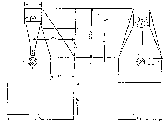
Figure 1
8.2.2. Description of the test:
8.2.2.1. The procedure used to clamp the rear‑view mirror to the support shall be that recommended by the manufacturer of the device, or, where appropriate, by the vehicle manufacturer.
8.2.2.2. Positioning the rear‑view mirror for the test.
8.2.2.2.1. Rear‑view mirrors shall be positioned on the pendulum impact rig such that the axes which are horizontal and vertical when installed on a vehicle in accordance with the vehicle or rear‑view mirror manufacturers' mounting instructions, are in a similar position.
8.2.2.2.2. When a rear‑view mirror is adjustable in relation to the base, the test position shall be the least favourable for any pivoting device to operate within the limits provided by the mirror or vehicle manufacturer.
8.2.2.2.3. When the rear‑view mirror has a device for adjusting its distance from the base, the device shall be set in the position where the distance between the holder and the base is shortest.
8.2.2.2.4. When the reflecting surface is mobile in the holder, it shall be adjusted so that the upper corner which is furthest from the vehicle, is in the position of greatest projection relative to the holder.
8.2.2.3. When the pendulum is in a vertical position, the horizontal and longitudinal vertical planes passing through the centre of the hammer, shall pass through the centre of the mirror as defined in paragraph 2.7. above. The longitudinal direction of oscillation of the pendulum shall be parallel to the longitudinal plane of the vehicle.
8.2.2.4. When, under the conditions governing adjustment prescribed in paragraphs 8.2.2.2.1. and 8.2.2.2.2. above, parts of the rear‑view mirror limit the return of the hammer, the point of impact shall be shifted in a direction perpendicular to the axis of rotation or pivot in question. This displacement shall be that which is strictly necessary for the implementation of the test.
It shall be limited in such a way that the point of contact of the hammer is located at least 10 mm from the periphery of the reflecting surface.
8.2.2.5. The test consists in allowing the hammer to fall from a height corresponding to a pendulum angle of 60º from the vertical so that the hammer strikes the rear‑view mirror at the moment when the pendulum reaches the vertical position.
8.2.2.6. The rear‑view mirrors are subjected to impact in the following different conditions:
8.2.2.6.1. Test 1: The point of impact shall be as defined in paragraphs 8.2.2.3 or 8.2.2.4 above. The impact shall be such that the hammer strikes the rear‑view mirror on the reflecting surface side.
8.2.2.6.2. Test 2: The point of impact shall be as defined in paragraphs 8.2.2.3. or 8.2.2.4. above. The impact shall be such that the hammer strikes the rear‑view mirror on the opposite side to the reflecting surface.
8.3. Bending test on the holder fixed to the stem
8.3.1. Description of the test
8.3.1.1. The holder shall be placed horizontally in a device in such a way that the adjustment parts of the mounting can be clamped securely. In the direction of the greatest dimension of the holder, the end nearest to the point of fixing on the adjustment part shall be immobilized by means of a fixed step 15 mm wide, covering the entire width of the holder.
8.3.1.2. At the other end, a step identical with the one described above shall be placed on the holder so that the specified test load can be applied to it (see figure 2 below).
8.3.1.3. The end of the holder opposite that at which the force is applied may be clamped instead of kept in position as shown in figure 2.
Example of bending test apparatus for rear view mirror protective housings
Metal blocks
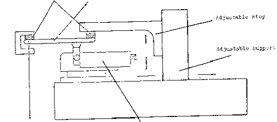
Clamping mechanism Weight P
Figure 2
8.3.2. The test load shall be 25 kg applied for one minute.
8.4. Results of the tests
8.4.1. In the tests described in paragraph 8.2. above, the pendulum shall return in such a way that the projection on the release plane of the position taken by the arm makes an angle of at least 20º with the vertical.
8.4.1.1. The accuracy of the angle measurement shall be +/1º.
8.4.2. The mirror shall not break during the tests described in paragraphs 8.2. and 8.3 above. However, breakage of the reflecting surface of the mirror shall be allowed if one of the following conditions is fulfilled:
8.4.2.1. The fragments of glass still adhere to the back of the holder or to a surface firmly attached to the holder, except that partial separation of the glass from its backing is permitted, provided this does not exceed 2.5 mm either side of the crack. It is permissible for small splinters to become detached from the surface of the glass at the point of impact;
8.4.2.2. The mirror is made of safety glass.
9. CONFORMITY OF PRODUCTION
9.1. Any rear‑view mirror approved pursuant to this Regulation shall be so manufactured as to conform to the type approved by meeting the requirements set forth in paragraphs 6. to 8. above.
9.2. In order to verify that the requirements of paragraph 9.1. are met, suitable controls of the production shall be carried out.
9.3. The holder of the approval shall, in particular:
9.3.1. Ensure existence of procedures for the effective control of the quality of rear‑view mirrors,
9.3.2. Have access to the control equipment necessary for checking the conformity of each approved type,
9.3.3. Ensure that data of test results are recorded and that annexed documents shall remain available for a period to be determined in accordance with the administrative service,
9.3.4. Analyse the results of each type of test, in order to verify and ensure the stability of the rear‑view mirror characteristics, making allowance for variation of an industrial production,
9.3.5. Ensure that for each type of rear‑view mirror at least the tests prescribed in annex 7 to this Regulation are carried out,
9.3.6. Ensure that any samples or test pieces giving evidence of non‑conformity with the type of test considered shall give rise to another sampling and another test. All the necessary steps shall be taken to re‑establish the conformity of the corresponding production.
9.4. The competent authority which has granted type‑approval may at any time verify the conformity control methods applicable to each production unit.
9.4.1. In every inspection, the test books and production survey records shall be presented to the visiting inspector.
9.4.2. The inspector may take samples at random which will be tested in the manufacturer's laboratory. The minimum number of samples may be determined according to the results of the manufacturer's own verification.
9.4.3. When the quality level appears unsatisfactory or when it seems necessary to verify the validity of the tests carried out in application of paragraph 9.4.2., the inspector shall select samples to be sent to the technical service which has conducted the type‑approval tests.
9.4.4. The competent authority may carry out any test prescribed in this Regulation.
9.4.5. The normal frequency of inspections authorized by the competent authority shall be one per two year. In the case where negative results are recorded during one of these visits, the competent authority shall ensure that all necessary steps are taken to re‑establish the conformity of production as rapidly as possible.
10. PENALTIES FOR NON‑CONFORMITY OF PRODUCTION
10.1. The approval granted in respect of a type of rear‑view mirror pursuant to this Regulation may be withdrawn if the requirements set forth above are not met.
10.2. If a Contracting Party to the Agreement applying this Regulation withdraws an approval it has previously granted, it shall forthwith so notify the other Contracting Parties applying this Regulation by means of a communication form conforming to the model in annex 1 to this Regulation.
11. MODIFICATION AND EXTENSION OF APPROVAL OF A TYPE OF REAR‑VIEW MIRROR
11.1. Every modification of the vehicle type shall be notified to the administrative department which approved the type of rear‑view mirror. The department may then either:
11.1.1. Consider that the modifications made are unlikely to have an appreciable adverse effect and that in any case the rear‑view mirror still complies with the requirements; or
11.1.2. Require a further test report from the technical service responsible for conducting the tests.
11.2. Confirmation or refusal of approval, specifying the alterations shall be communicated by the procedure specified in paragraph 5.3 above to the Parties to the Agreement applying this Regulation.
11.3. The competent authority issuing the extension of approval shall assign a series number for such an extension and inform thereof the other Parties to the 1958 Agreement applying this Regulation by means of a communication form conforming to the model in annex 1 to this Regulation.
12. PRODUCTION DEFINITELY DISCONTINUED
If the holder of the approval completely ceases to manufacture a type of rear‑view mirror approved in accordance with this Regulation, he shall so inform the authority which granted the approval. Upon receiving the relevant communication that authority shall inform thereof the other Parties to the 1958 Agreement applying this Regulation by means of a communication form conforming to the model in annex 1 to this Regulation.
II ‑ INSTALLATION OF REAR‑VIEW MIRRORS
13. DEFINITIONS
For the purpose of this Regulation,
13.1. "The maximum design speed" as specified in paragraph 16.2. of this Regulation.
13.2. "Type of vehicle as regards rear‑view mirrors" means vehicles which are identical in respect of the following basic features:
13.2.1. The geometrical features of the vehicle, liable to influence the installation of rear‑view mirrors,
13.2.2. The positions and types of rear‑view mirror specified.
14. APPLICATION FOR APPROVAL
14.1. The application for approval of a vehicle type with regard to the installation of rear‑view mirrors shall be submitted by the vehicle manufacturer or by his duly accredited representative.
14.2. It shall be accompanied by the undermentioned documents in triplicate and by the following particulars:
14.2.1. A description of the vehicle type with respect to the items mentioned in paragraph 13.2. above;
14.2.2. A list of the components necessary to identify rear‑view mirrors which can be installed in the vehicle;
14.2.3. Drawings showing the position of the rear‑view mirror and its adapting components on the vehicle.
14.3. A vehicle representative of the vehicle type to be approved shall be submitted to the technical service responsible for conducting the approval tests.
14.4. The competent authority shall verify the existence of satisfactory arrangements for ensuring effective control of the conformity of production before type‑approval is granted.
15. APPROVAL
15.1. If the vehicle type submitted for approval in accordance with paragraph 14 above meets the requirements of paragraph 16 of this Regulation, approval shall be granted.
15.2. An approval number shall be assigned to each type approved. Its first two digits (at present 00, for the Regulation in its original form) shall indicate the series of amendments incorporating the most recent major technical amendments made to the Regulation at the time of issue of the approval. The same Contracting Party may not assign the same number to another vehicle type.
15.3. Notice of approval or of extension or refusal of approval of a vehicle type pursuant to this Regulation shall be communicated to the Parties to the 1958 Agreement applying this Regulation, by means of a form conforming to the model in annex 2 to this Regulation.
15.4. There shall be affixed, conspicuously and in a readily accessible place specified on the approval form, to every vehicle conforming to a type approved under this Regulation an international approval mark consisting of:
15.4.1. A circle surrounding the letter "E" followed by the distinguishing number of the country which has granted approval,
15.4.2. The number of this Regulation, followed by the letter "R", a dash and the approval number to the right of the circle prescribed in paragraph 15.4.1.
15.5. If the vehicle conforms to a vehicle type approved, under one or more other Regulations annexed to the Agreement, in the country which has granted approval under this Regulation, the symbol prescribed in paragraph 15.4.1. need not be repeated; in such a case, the Regulation and approval numbers and the additional symbols of all the Regulations under which approval has been granted in the country which has granted approval under this Regulation shall be placed in vertical columns to the right of the symbol prescribed in paragraph 15.4.1.
15.6. The approval mark shall be clearly legible and be indelible.
15.7. The approval mark shall be placed close to or on the vehicle data plate affixed by the manufacturer.
15.8. Annex 4 to this Regulation gives examples of arrangements of the approval mark.
16. REQUIREMENTS
16.1. The vehicle shall meet the following requirements:
16.1.1. The rear‑view mirrors installed on the vehicle shall be of Class/L type approved under this Regulation.
16.1.2. Rear‑view mirrors shall be fixed in such a way that they remain steady under normal conditions of use.
16.2. Number
16.2.1. All two-wheeled vehicles with a maximum design speed not exceeding 50 km/h must be fitted with at least one rear-view mirror. If one only, this rear-view mirror must be fitted on the left side of the vehicle in countries with right‑hand rule of the road, and on the right side of the vehicle in countries with left‑hand rule of the road.
16.2.2. All two-wheeled vehicles with a maximum design speed exceeding 50 km/h and all three-wheeled vehicles must be fitted with two rear-view mirrors, one on the left and one on the right of the vehicle.
16.3. Site
16.3.1. Rear‑view mirrors must be mounted or adjusted in such a way that the distance of the centre of the reflective surface, as measured in a horizontal plane, is at least 280 mm outward from the longitudinal vertical plane passing through the centre of the steering head of the vehicle. Before the measurement, the handlebar shall be placed in the straight ahead position and the mirror(s) shall be adjusted to its (their) normal position.
16.4. Adjustment
16.4.1. Rear‑view mirror(s) shall be such that the driver can adjust it (them) in the normal driving position.
17. CONFORMITY OF PRODUCTION
17.1. Any vehicle approved pursuant to this Regulation shall be so manufactured as to conform to the type approved by meeting the requirements set out in paragraph 16 above.
17.2. In order to verify that the requirements of paragraph 17.1. above are met, suitable controls of the production shall be carried out.
17.3. The holder of the approval shall in particular:
17.3.1. Ensure existence of procedures for the effective control of the quality of the vehicles as regards all aspects relevant for compliance with the requirements set out in paragraph 16 above;
17.3.2. Ensure that for each type of vehicle sufficient checks are carried out as regards the number and type of the rear‑view mirrors and the dimensions relevant for their correct installation in order to ensure that all vehicles in production comply with the specifications given for the vehicle which was submitted for type‑ approval;
17.3.3. Ensure that, if the checks carried out pursuant to paragraph 17.3.2. above give evidence of non‑conformity of one or more vehicles with the requirements set out in paragraph 16 above, all necessary steps are taken to re‑establish the conformity of the corresponding production.
17.4. The competent authority which has granted type‑approval may at any time verify the conformity control methods applicable to each production unit. It may also carry out any random checks on serially‑manufactured vehicles regarding the requirements set out in paragraph 16 above.
17.5. In the case where negative results are recorded during the verifications and checks pursuant to paragraph 17.4. above, the competent authority shall ensure that all necessary steps are taken to re‑establish the conformity of production as rapidly as possible.
18. PENALTIES FOR NON‑CONFORMITY OF PRODUCTION
18.1. The approval granted in respect of a vehicle type pursuant to this Regulation may be withdrawn if the requirements set forth above are not met.
18.2. If a Contracting Party to the Agreement applying this Regulation withdraws an approval it has previously granted, it shall forthwith so notify the other Contracting Parties applying this Regulation, by means of a communication form conforming to the model in annex 1 to this Regulation.
19. MODIFICATION AND EXTENSION OF APPROVAL OF THE VEHICLE TYPE
19.1. Every modification of the vehicle type shall be notified to the administrative department which approved the vehicle type. The department may then either:
19.1.1. Consider that the modifications made are unlikely to have an appreciable adverse effect and that in any case the vehicle still complies with the requirements; or
19.1.2. Require a further test report from the technical service responsible for conducting the tests.
19.2. Confirmation or refusal of approval, specifying the alterations shall be communicated by the procedure specified in paragraph 15.3 above to the Parties to the Agreement applying this Regulation.
19.3. The competent authority issuing the extension of approval shall assign a series number for such an extension and inform thereof the other Parties to the 1958 Agreement applying this Regulation by means of a communication form conforming to the model in annex 2 to this Regulation.
20. PRODUCTION DEFINITELY DISCONTINUED
If the holder of the approval completely ceases to manufacture a vehicle type approved in accordance with this Regulation, he shall so inform the authority which granted the approval. Upon receiving the relevant communication, that authority shall inform thereof the other Parties to the 1958 Agreement applying this Regulation by means of a communication form conforming to the model in annex 2 to this Regulation.
21. NAMES AND ADDRESSES OF TECHNICAL SERVICES RESPONSIBLE FOR CONDUCTING APPROVAL TESTS AND OF ADMINISTRATIVE DEPARTMENTS
The Parties to the 1958 Agreement applying this Regulation shall communicate to the United Nations Secretariat the names and addresses of the technical services responsible for conducting approval tests and of the administrative departments which grant approval and to which forms certifying approval or extension or refusal or withdrawal of approval, issued in other countries, are to be sent.
Annex 1
(maximum format: A4 (210 x 297 mm))

COMMUNICATION
issued by: Name of administration:
.......................
.......................
.......................
concerning: APPROVAL GRANTED
APPROVAL EXTENDED
APPROVAL REFUSED
APPROVAL WITHDRAWN
PRODUCTION DEFINITIVELY DISCONTINUED
of a type of rear‑view mirror pursuant to Regulation No. 81
Approval No. ... Extension No. ...
1. Trade name or mark of the equipment: ....................................
2. Equipment type: .........................................................
3. Brief description including in particular the following information:
3.1. Main dimensions ) of the reflecting surface
3.2. Nominal radius of curvature)
4. Manufacturer's name and address: .......................................
5. If applicable, name and address of manufacturer's representative: ......................................
6. Equipment submitted for approval on: ...................................
7. Technical service responsible for conducting approval tests: ...................................................
8. Date of report issued by that service: ..................................
9. Number of report issued by that service: ................................
10. Vehicles for which the equipment is designed:.......................................................................
11. Approval is granted/refused/extended/withdrawn 2/
12. Reason(s) for extension of approval: ....................................
13. Place: .............................
14. Date: ..............................
15. Signature: .........................
16. A list of documents contained in the approval file transmitted to the administrative service which has granted approval is annexed to this communication.
_______________
Annex 2
(maximum format: A4 (210 x 297 mm))
COMMUNICATION
issued by: Name of administration:
.......................
.......................
.......................
concerning: APPROVAL GRANTED
APPROVAL EXTENDED
APPROVAL REFUSED
APPROVAL WITHDRAWN
PRODUCTION DEFINITIVELY DISCONTINUED
of a type of vehicle with regard to the installation of rear‑view mirrors pursuant to Regulation No. 81
Approval No. ... Extension No. ...
1. Trade name or mark of the vehicle: ......................................
2. Vehicle type: ...........................................................
3. Vehicle maximum design speed: 2/ 50 km/h / > 50 km/h
4. Manufacturer's name and address: ......................................................................................
5. If applicable, name and address of manufacturer's representative: ......................................
6. Trade name or mark of rear‑view mirror(s): .............................
7. Approval mark of the rear mirror: .......................................
8. Vehicle submitted for approval on: ......................................
9. Technical service responsible for conducting approval tests: ............
10. Date of report issued by that service: ..................................
11. Number of report issued by that service: ................................
12. Approval is granted/refused/extended/withdrawn 2/
13. Reason(s) for extension of approval: ....................................
14. Place: .............................
15. Date: ..............................
16. Signature: .........................
17. A list of documents contained in the approval file transmitted to the administrative service which has granted approval is annexed to this communication.
______________
Annex 3
ARRANGEMENT OF THE REAR‑VIEW MIRROR APPROVAL MARK
(See paragraph 5.4. of the Regulation)
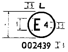
a = 8 mm min
The above approval mark affixed to a rear‑view mirror indicates that the mirror is a rear‑view mirror, of type L, which has been approved in the/Netherlands (E 4) under approval number 002439. The first two digits of the approval number indicate that the approval was granted in accordance with the requirements of Regulation No./81 in its original form.
Note: The approval number and the additional symbol must be placed close to the circle and either above or below the "E" or to the left or right of that letter. The digits of the approval number must be on the same side of the "E" and point in the same direction. The additional symbol must be directly opposite the approval number. The use of Roman numerals as approval numbers should be avoided so as to prevent any confusion with other symbols.
___________________
Annex 4
ARRANGEMENTS OF THE VEHICLE APPROVAL MARK CONCERNING THE INSTALLATION OF REAR‑VIEW MIRRORS
Model A
(See paragraph 15.4. of the Regulation)
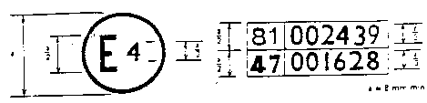
The above approval mark affixed to a vehicle shows that the vehicle type concerned has been approved in the Netherlands (E 4) pursuant to Regulation No. 81 under approval number 002439. The first two digits of the approval number indicate that the approval was granted in accordance with the requirements of Regulation No. 81 in its original form.
Model B
(See paragraph 15.5. of the Regulation)
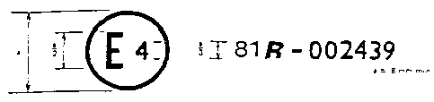
The above approval mark affixed to a vehicle shows that the vehicle type concerned has been approved in the Netherlands (E 4) pursuant to Regulations Nos. 81 and 47. The first two digits of the approval numbers indicate that, at the dates when the respective approvals were granted, Regulation
No. 81 had not been modified, and Regulation No. 47 already included the 01 series of amendments.
.
Annex 5
TEST METHOD FOR DETERMINING REFLECTIVITY
1. DEFINITIONS
1.1. CIE standard illuminant A:
λ  ( λ )
( λ )
600 1.062 2
620 0.854 4
650 0.283 5
1.2. CIE standard source A: 1/ Gas‑filled tungsten filament lamp operating at a correlated colour temperature of T68 = 2,855.6 K.
1.3. CIE 1931 standard colorimetric observer: 1/ Receptor of radiation whose colorimetric characteristics correspond to the spectral tristimulus values  ( λ), y( λ ), z (λ ) (see table).
1.4. CIE spectral tristimulus values: 1/ Tristimulus values of the spectral components of an equi‑energy spectrum in the CIE (XYZ) system.
1.5. Photopic vision: 1/ Vision by the normal eye when it is adapted to levels of luminance of at least several candelas per square metre.
2. APPARATUS
2.1. General
2.1.1. The apparatus shall consist of a light source, a holder for the test sample, a receiver unit with a photodetector and an indicating meter (see figure 1), and a means of eliminating the effects of extraneous light.
2.1.2. The receiver may incorporate a light‑integrating sphere to facilitate measuring the reflectance of non‑flat (convex) mirrors (see figure 2).
2.2. Spectral characteristics of light source and receiver.
2.2.1. The light source shall consist of a CIE standard source A and associated optics to provide a near‑collimated light beam. A voltage stabilizer is recommended to maintain a fixed lamp voltage during instrument operation.
2.2.2. The receiver shall have a photodetector with a spectral response proportional to the photopic luminosity function of the CIE (1931) standard colorimetric observer (see table). Any other combination of illuminant‑filter‑receptor giving the overall equivalent of CIE standard illuminant A and photopic vision may be used. When an integrating sphere is used in the receiver, the interior surface of the sphere shall be coated with a matt (diffusive) spectrally non‑selective white coating.
2.3. Geometric conditions
2.3.1. The angle of the incident beam (0) should preferably be 0.44 +0.09 rad (25 + 5º) from the perpendicular to the test surface and shall not exceed the upper limit of the tolerance (i.e. 0.53 rad or 30º). The axis of the receptor shall make an angle (0) with this perpendicular equal to that of the incident beam (see figure 1). The incident beam upon arrival at the test surface shall have a diameter of not less than 19 mm. The reflected beam shall not be wider than the sensitive area of the photodetector, shall not cover less than 50% of such area, and as nearly as possible shall cover the same area segment as used during instrument calibration.
2.3.2. When an integrating sphere is used in the receiver section, the sphere shall have a minimum diameter of 127 mm. The sample and incident beam apertures in the sphere wall shall be of such a size as to admit the entire incident and reflected light beams. The photodetector shall be located so as not to receive direct light from either the incident or the reflected beams.
2.4. Electrical characteristics of the photodetector‑indicator unit
The photodetector output as read on the indicating meter shall be a linear function of the light intensity on the photosensitive area. Means (electrical and/or optical) shall be provided to facilitate zeroing and calibration adjustments. Such means shall not affect the linearity or the spectral characteristics of the instrument. The accuracy of the receptor‑indicator unit shall be with + 2% of full scale, or +10% of the magnitude of the reading, whichever is the smaller.
2.5. Sample holder
The mechanism shall be capable of locating the test sample so that the axes of the source arm and receptor are intersect at the reflecting surface. The reflecting surface may lie within or at either face of the mirror sample, depending on whether it is a first‑surface, second‑surface, or prismatic "flip" type mirror.
3. PROCEDURE
3.1. Direct calibration method
3.1.1. In the direct calibration method, air is used as the reference standard. This method is applicable for those instruments which are so constructed as to permit calibration at the 100% point by swinging the receiver to a position directly on the axis of the light source (see figure/1).
3.1.2. It may be desired in some cases (such as when measuring low‑reflectivity surfaces) to use an intermediate calibration point (between 0 and 100% on the scale) with this method. In these cases a neutral density filter of known transmittance shall be inserted in the optical path, and the calibration control shall then be adjusted until the meter reads the percentage transmission of the neutral density filter. This filter shall be removed before making reflectivity measurements.
3.2. Indirect calibration method
The indirect calibration method is applicable for those instruments with fixed source and receiver geometry. A properly calibrated and maintained reflectance standard is required. This reference standard should preferably be a flat mirror with a reflectance value as near as possible to that of the test samples.
3.3. Non‑flat (convex) mirror measurement
The measurement of the reflectance of non‑flat (convex) mirrors requires the use of instruments which incorporate an integrating sphere in the receiver unit (see figure 2). If the instrument indicating meter indicates ne divisions with a reference standard mirror of E per cent reflectance, then, with a mirror of unknown reflectance, nx divisions will correspond to a reflectance of X per cent, given by the formula:

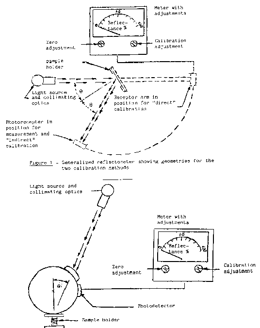
Figure 2 - Generalized reflectometer, incorporating an integrating sphere in the receptor.
SPECTRAL TRISTIMULUS VALUES FOR THE CIE 1931 STANDARD COLORIMETRIC OBSERVER
(This table is taken from CIE Publication 50(45) (1970))
λ x ( λ )  ( λ )
( λ )  ( λ ) nm
380 0.001 4 0.000 0 0.006 5
390 0.004 2 0.000 1 0.020 1
400 0.014 3 0.000 4 0.067 9
410 0.043 5 0.001 2 0.207 4
420 0.134 4 0.004 0 0.645 6
430 0.283 9 0.011 6 1.385 6
440 0.348 3 0.023 0 1.747 1
450 0.336 2 0.038 0 1.772 1
460 0.290 8 0.060 0 1.669 2
470 0.195 4 0.091 0 1.287 6
480 0.095 6 0.139 0 0.813 0
490 0.032 0 0.208 0 0.465 2
500 0.004 9 0.323 0 0.272 0
510 0.009 3 0.503 0 0.158 2
520 0.063 3 0.710 0 0.078 2
530 0.165 5 0.862 0 0.042 2
540 0.290 4 0.954 0 0.020 3
550 0.433 4 0.995 0 0.008 7
560 0.594 5 0.995 0 0.003 9
570 0.762 1 0.952 0 0.002 1
580 0.916 3 0.870 0 0.001 7
590 1.026 3 0.757 0 0.001 1
600 1.062 2 0.631 0 0.000 8
610 1.002 6 0.503 0 0.000 3
620 0.854 4 0.381 0 0.000 2
630 0.642 4 0.265 0 0.000 0
640 0.447 9 0.175 0 0.000 0
650 0.233 5 0.107 0 0.000 0
660 0.164 9 0.061 0 0.000 0
670 0.087 4 0.032 0 0.000 0
680 0.046 8 0.017 0 0.000 0
690 0.022 7 0.008 2 0.000 0
700 0.011 4 0.004 1 0.000 0
710 0.005 8 0.002 1 0.000 0
720 0.002 9 0.001 0 0.000 0
730 0.001 4 0.000 5 0.000 0
740 0.000 7 0.000 2 0.000 0
750 0.000 3 0.000 1 0.000 0
760 0.000 2 0.000 1 0.000 0
770 0.000 1 0.000 0 0.000 0
780 0.000 0 0.000 0 0.000 0
‑‑‑‑‑‑‑‑‑‑‑‑‑‑‑‑‑‑‑‑‑‑‑‑‑‑‑‑‑‑‑‑‑‑‑‑‑‑‑‑‑‑‑‑‑‑‑‑‑‑‑‑‑
EXPLANATORY FIGURE
Example of device for measuring the reflection factor of spherical mirrors
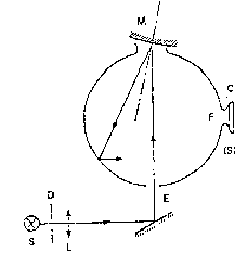
C = Receiver
D = Diaphragm
E = Window of entry
F = Window of measurement
L = Lens
M = Object window
S = Light source
(S) = Integrating sphere
_________________
Annex 6
PROCEDURE FOR DETERMINING THE RADIUS OF CURVATURE "r" OF A MIRROR'S REFLECTING SURFACE
1. Measurements
1.1. Equipment
The "spherometer" described in figure/1 is used.
1.2. Measuring points
1.2.1. The principal radii of curvature shall be measured at 3 points situated as close as possible to positions at 1/3, 1/2 and 2/3 of the distance along the arc of the reflecting surface contained in a plane parallel to the greatest dimension of the mirror and passing through its centre and of the arc perpendicular to it.
1.2.2. Where, because of mirror size, it is impossible to obtain measurement in the directions defined in item/1.2.1. the technical departments responsible for the tests may take measurements at this point in two perpendicular directions as close as possible to those prescribed above.
2. Calculation of the radius of curvature (r)
"r" expressed in mm is calculated using the formula:

where rp1 is the radius of curvature of the first measuring point, rp2 at the second and rp3 at the third.
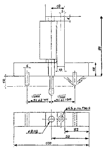
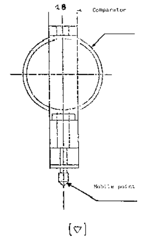
Figure 1
Annex 7
CONTROL OF THE CONFORMITY OF PRODUCTION
1. DEFINITIONS
For the purpose of this annex,
"Type of deflection system" means a given combination of axes, swivel points and other articulating mechanisms which ensures deflection of the rear‑view mirror in the direction of impact concerned.
2. TESTS
Rear‑view mirrors shall be subjected to the following tests:
2.1. Reflecting surface
2.1.1. Verification of the nominal radius of curvature, pursuant to the requirements of paragraph 2 of annex6 to this Regulation;
2.1.2. Measurement of the differences between radii of curvature pursuant to the requirements of paragraph 7.2.2. of this Regulation.
2.2. Deflection system
Impact test pursuant to the requirements of paragraph 8.2. of this Regulation.
3. FREQUENCY AND RESULTS OF TESTS
3.1. Verification of the nominal radius of curvature and measurement of the differences between radii of curvature
3.1.1. Frequency:
One test every three months, per approval number, per nominal radius of curvature.
3.1.2. Results:
All measurement results shall be recorded.
The maximum difference values prescribed in paragraph 7.2.2. of this Regulation shall be complied with.
3.2. Impact test
3.2.1. Frequency:
One test every three months, per approval number, per type of deflection system, per base configuration.
3.2.2. Results:
All results shall be recorded.
The provisions of paragraph 8.4. of this Regulation shall be complied with.
3.3. Selection of samples
The selection of samples to be tested shall take account of the quantity produced for each type of rear‑view mirrors.
Appendix C – ADR 14/02 - Rear Vision Mirrors
- definitions
- Refer to Vehicle Standard (Australian Design Rule Definitions and Vehicle Categories) 2005,
- REQUIREMENTS FOR LEP; MA; MB; MC; AND MD1 VEHICLES ONLY
2.0. Any internal rear vision mirror fitted to a vehicle and intended to provide the driver with a view of following or overtaking vehicles shall have a flat reflecting surface i.e. of unit magnification.
2.1. An external mirror complying with the requirement of Clause 2.3 shall be fitted on the driver’s side of the vehicle. An internal rear vision mirror shall also be provided except where the design of the motor vehicle does not provide for internal rear vision. In any case where the field of view requirements of Clause 2.2.1 are not met the vehicle shall be equipped with a passenger’s side external rear vision mirror complying with Clause 2.3.2.
2.2. Internal Rear Vision Mirrors
2.2.1. Field of View - An internal mirror shall be installed that provides all drivers (with eyes located by the ‘95th Percentile Eye Ellipses’ tangent contours) with a view to the rear, with an included horizontal angle of at least 20 degrees and sufficient vertical angle to provide a view of a level road surface extending to the horizon beginning at a point not greater than 61 metres to the rear of the vehicle when the vehicle is occupied by the driver and 4 passengers or the designated ‘Seating Capacity’, if less, based on 68 kg average occupant mass. The line of sight may be partially obscured by seated occupants or by ‘Head Restraints’.
2.2.2. Mounting
2.2.2.1. The mirror mounting shall provide a stable support for the mirror, and shall provide for adjustment by tilting in both horizontal and vertical directions.
2.2.2.2. If the mirror is in the ‘Head Impact Area’, the mounting shall deflect, collapse or break away without leaving sharp edges when the reflective surface of the mirror is subjected to a force of not more than 400 N in any ‘Forward’ direction that is not more than 45 degrees from the ‘Forward’ longitudinal direction.
2.3. External Rear Vision Mirrors
2.3.1. Driver’s Side
2.3.1.1. Field of View - A flat external mirror shall be installed that provides all drivers (with eyes located by the ‘95th Percentile Eye Ellipses’ tangent contours) with a view of a level road surface extending to the horizon from a line perpendicular to a plane tangential to the driver’s side of the vehicle at the widest point and parallel to the longitudinal axis of the vehicle, extending 2.4 metres out from the tangential plane 11 metres behind the driver’s eyes, with the ‘Seat’ in the rearmost position. The line of sight may be partially obscured by rear body or wheel guard contours. A convex mirror complying with the technical requirements of Appendix A may be used instead of a flat mirror.
2.3.1.2. Mounting - The mirror mounting shall provide a stable support for the mirror and neither the mirror nor the mounting shall protrude further than the widest part of the vehicle body, except to the extent necessary to produce a field of view meeting the requirements of Clause 2.3.1.1. The mirror shall not be obscured by the unwiped portion of the windscreen, and shall be adjustable from the driver’s seating position. The mirror and mounting shall be free of sharp points or edges that could contribute to pedestrian injury.
2.3.2. Passenger’s Side
2.3.2.1. Where a left-hand external mirror is provided in compliance with Clause 2.1 its mounting shall provide a stable support for the mirror. The mirror and mounting shall be free of sharp points or edges that could contribute to pedestrian injury. The mirror need not be adjustable from the driver’s seating position, but shall be capable of adjustment by tilting in both horizontal and vertical directions.
2.3.2.2. The mirror shall be flat or convex.
2.3.2.3. For ‘Convex Mirrors’ the reflective surface area is to be equal to or greater than that of a flat mirror required to meet the field of view requirements set out in Clause 2.3.1.1.
2.4. Mirror Construction
2.4.1. Reflectance
The reflectance value of the reflective film employed shall be at least 35 per cent. If a mirror is of the selective position prismatic type, the reflectance value in the night driving position shall be at least 4 per cent.
2.4.2. ‘Convex Mirrors’
Each motor vehicle using a ‘Convex Mirror’ to meet the requirements of Clause 2.3.2 shall comply with the following requirements:
2.4.2.1. the radii of curvature shall not deviate by more than plus or minus 15 per cent from the average radius of curvature when measured in accordance with the procedures specified in Annex 1.
2.4.2.2. the average radius of curvature is not to be less than 1,200 mm.
2.5. Test Procedure
2.5.1. Reflectance shall be determined in accordance with SAE document J964a "Test Procedure for Determining Reflectivity of Rearview Mirror", August, 1974.
2.5.2. The horizontal angle is measured from the projected eye point rather than the plane of the mirror.
3. REQUIREMENTS FOR VEHICLES OF CATEGORY LEG; NA AND MD2 ONLY
Vehicles of category NA, LEG and MD2 shall have mirrors which comply with Clause 2 or 4.
4. REQUIREMENTS FOR MD3; MD4; ME; NB; AND NC VEHICLES ONLY
4.1. There shall be affixed to every vehicle a mirror or mirrors so designed and fitted and of such dimensions as to be capable of reflecting to the driver as far as practicable a clear view of the road to the rear of him and of any following or overtaking vehicle.
4.2. At least one such mirror shall be affixed to each side of the vehicle and may project 150 mm beyond the point of ‘Overall Width’ of the vehicle or the ‘Overall Width’ of any trailer it may be drawing-
4.2.1. if the vehicle is a goods vehicle or an omnibus;
4.2.2. if the trailer be of greater width than the drawing vehicle; or
4.2.3. in any case where, because of the manner in which the vehicle is constructed or equipped, or the fact that it is drawing a trailer or for any other reason, the driver could not, by means of a mirror affixed to the inside of the vehicle, have reflected to him as far as practicable a clear view of the road to the rear of him and of any following or overtaking vehicle.
4.3. The mirrors may project 230 mm on each side beyond the point of ‘Overall Width’ of the vehicle provided that the mirror is capable of collapsing to 150 mm.
4.4. All such mirrors fitted to vehicles shall be at least 150 square centimetres in area.
4.5. Mirrors on the driver’s side shall be flat, and mirrors on the passenger’s side may be flat or convex.
4.5.1. ‘Convex mirrors’, if fitted, shall meet the requirements of Clauses 2.4.2.1 and 2.4.2.2.
5. REQUIREMENTS FOR LA; LB; LC; LD AND LEM GROUP VEHICLES ONLY
5.1. All vehicles shall be equipped with 2 rear vision mirrors having the same curvature (including flatness), symmetrically placed relative to the centre of the steering control and of such dimensions as to be capable of reflecting to the driver as far as practicable a clear view of the road to the rear of him and of any following or overtaking vehicle.
5.1.1. Flat mirrors shall have not less than 80 square centimetres of reflective surface.
5.1.2. ‘Convex Mirrors’ shall have not less than 64.5 square centimetres of reflective surface and an average radius of curvature that is not less than 1,200 mm.
6. ADDITIONAL EXTERNAL REAR VISION MIRRORS
6.1. Mirrors in addition to those required by this Rule may also be fitted, provided that:
6.1.1. they do not protrude or project beyond the vehicle more than allowed for other mirrors required by this Rule.
6.1.2. they do not obstruct or interfere with the field of view requirements provided by mirrors fitted to meet the specified requirements of this Rule.
6.1.3. if the mirror is the only mirror on the left-hand side it shall be flat or convex with an average radius of curvature of at least 1,200 mm.
6.2. Additional mirrors need not meet the requirements of Clause 2.4.2.2 except as specified in Clause 6.1.3 above.
Annex 1
(EXTRACTED FROM FMVSS 111 "REAR VIEW MIRRORS", SECTION 12)
S12 Determination of Radius of Curvature.
S12.1 To determine the average radius of curvature of a convex mirror, use a 3-point linear spherometer, which meets the requirements of S12.2, at the 10 test positions shown in Figure 1 and record the readings for each position.
S12.2 The 3-point linear spherometer has two outer fixed legs 1.5 inches apart and one inner movable leg at the mid- point. The spherometer has a dial indicator with a scale that can be read accurately to 0.0001 inches, with the zero reading being a flat surface.
S12.3 The 10 test positions on the image display consist of two positions at right angles to each other at each of five locations as shown in Figure 1. The locations are at the centre of the mirror, at the left and right ends of a horizontal line that bisects the mirror and at the top and bottom ends of a vertical line that bisects the mirror. None of the readings are within a 0.25 inch border on the edge of the image display.
S12.4 At each position, the spherometer is held perpendicular to the convex mirror-surface and a record is made of the reading on the dial indicator to the nearest 0.0001 inch.
S12.5 Convert the dial reading data for each of the 10 test positions to radius of curvature calculations using the following formula.

where R = Radius of curvature
H = Linear displacement of the centre probe
C = Chord Length = 1.5 inches
S12.6 Calculate the average radius of curvature by adding all 10 radius of curvature calculations and dividing by ten.
S12.7 Determine the numerical difference between the average radius of curvature and each of the 10 individual radius of curvature calculations determined in S12.5.
S12.8 Calculate the greatest percentage deviation by dividing the greatest numerical difference determined in S12.7 by the average radius of curvature and multiply by 100.
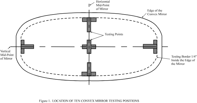
/ Former title of the Agreement:
Agreement Concerning the Adoption of Uniform Conditions of Approval and Reciprocal Recognition of Approval for Motor Vehicle Equipment and Parts, done at Geneva on 20 March 1958.