CONTENTS
legislative provisions.....................................................
Purpose and SCOPE.....................................................
APPLICABILITY.......................................................
44.1. DEFINITIONS...................................................
44.2. REQUIREMENTS................................................
legislative provisions
44.0.1. NAME OF STANDARD
44.0.1.1. This Standard is the Vehicle Standard (Australian Design Rule 44/00 – Specific Purpose Vehicle Requirements) 2006.
44.0.1.2. This Standard may also be cited as Australian Design Rule 44/00 — Specific Purpose Vehicle Requirements.
44.0.2. COMMENCEMENT
44.0.2.1. This Standard commences on the day after it is registered.
44.0.3. REPEAL
44.0.3.1. This Standard repeals each vehicle standard with the name Australian Design Rule 44/00 — Specific Purpose Vehicle Requirements that is:
(a) made under section 7 of the Motor Vehicle Standards Act 1989; and
(b) in force at the commencement of this Standard.
44.0.3.2. This Standard also repeals each instrument made under section 7 of the Motor Vehicle Standards Act 1989 that creates a vehicle standard with the name Australian Design Rule 44/00 — Specific Purpose Vehicle Requirements, if there are no other vehicle standards created by that instrument, or amendments to vehicle standards made by that instrument, that are still in force at the commencement of this Standard.
Purpose and SCOPE
This Australian Design Rule (ADR) is part of the Australian motor vehicle standards system and is a national standard for the purpose of the Motor Vehicle Standards Act 1989.
The function of this Australian Design Rule is to specify requirements for the construction of vehicles designed for a specific purpose. The requirements include those for the mechanical coupling of vehicles. The requirements of ADR 44 are related to specific requirements of the particular vehicles. A "specific purpose vehicle" will belong to one or more of the vehicle categories.
APPLICABILITY
This ADR applies to the design and construction of vehicles as set out in the table hereunder.
The Package 11 issue of /00 amends the requirements for LPG fuel systems (Section 44.2.6).
Vehicles which comply with the requirements of ADR 44/01 & ADRs 62)00, 63/00 & 64/00 (as appropriate for the vehicle) need not comply with ADR 44/00.
Vehicle Category | ADR Category Code | UNECE Category Code * | Manufactured on or After | Acceptable Prior Rules |
Moped 2 wheels | LA | L1 | 1 July 1988 | Nil |
Moped 3 wheels | LB | L2 | 1 March 1991 | Nil |
Motor cycle | LC | L3 | 1 July 1988 | Nil |
Motor cycle and sidecar | LD | L4 | 1 July 1988 | Nil |
Motor tricycle | LE | L5 | 1 March 1991 | Nil |
Passenger car | MA | M1 | 1 July 1988 | Nil |
Forward-control passenger vehicle | MB | M1 | 1 July 1988 | Nil |
Off-road passenger vehicle | MC | M1 | 1 July 1988 | Nil |
Light omnibus | MD | M2 | | |
| up to 3.5 tonnes ‘GVM’ and up to 12 seats | MD1 | | 1 July 1988 | Nil |
| up to 3.5 tonnes ‘GVM’ and more than 12 seats | MD2 | | 1 July 1988 | Nil |
| over 3.5 tonnes and up to 4.5 tonnes ‘GVM’ | MD3 | | 1 July 1988 | Nil |
| over 4.5 tonnes and up to 5 tonnes ‘GVM’ | MD4 | | 1 July 1988 | Nil |
Heavy omnibus | ME | M3 | 1 July 1988 | Nil |
Light goods vehicle | NA | N1 | 1 July 1988 | Nil |
Medium goods vehicle | NB | N2 | | |
| over 3.5 tonnes up to 4.5 tonnes ‘GVM’ | NB1 | | 1 July 1988 | Nil |
| over 4.5 tonnes up to 12 tonnes ‘GVM’ | NB2 | | 1 July 1988 | Nil |
Heavy goods vehicle | NC | N3 | 1 July 1988 | Nil |
Very light trailer | TA | O1 | 1 July 1988 | Nil |
Light trailer | TB | O2 | 1 July 1988 | Nil |
Medium trailer | TC | O3 | 1 July 1988 | Nil |
Heavy trailer | TD | O4 | 1 July 1988 | Nil |
44.1. DEFINITIONS
44.1.1. Refer to Vehicle Standard (Australian Design Rule Definitions and Vehicle Categories) 2005.
44.1.2. ‘taxi' - a vehicle manufactured for up to 8 passengers which is to be used for the carriage of passengers for hire and reward. (This term embraces vehicles such as “Taxi Cabs" and "Hire Cars".
44.1.3. `Tow Tuck' - a goods vehicle equipped with a `Crane’ used or intended to be used for the lifting and carrying or towing of vehicles and includes any goods vehicle to which is attached (temporarily or otherwise) for the lifting and carrying of vehicles.
44.2. REQUIREMENTS
44.2.0. This Rule covers additional design and construction requirements for vehicles as specific purpose vehicles, where they fall within a vehicle category, e.g. `Tow Truck’ into NA, NB or NC and 'Taus' into MA, MB or MC they must also comply with all requirements of those vehicles as set out in individual Australian Design Rules.
44.2.1. ‘TAXIS'
44.2.1.1. General
All ‘Taxis’ shall comply with the special requirements of this Section.
44.2.1.2. Access to and from vehicle
44.2.1.2.1. An access door shall be provided adjacent to each 'Outboard Seating Position' for MA category vehicles
44.2.1.2.2. A device shall be fitted to the inside of each access door to allow operation of the door latch
44.2.1.3. Passenger `Seats'
44.2.1.3.1. The exposed surfaces of `Seats' shall be covered with non-absorbent materials.
44.2.1.3.2. Removable seat covers if fitted shall be made of non-absorbent or washable material.
44.2.1.4. Appointments
44.2.1.4.1. The exposed surface of interior roof linings and other interior trimming shall be of non-absorbent material.
44.2.1.4.2. The exposed surface of interior luggage compartment floor coverings small be of non-absorbent material
44.2.1.5. Interior Lighting
44.2.1.5.1. An interior lamp(s) shall be provided which, when nj1luminated, shows white light for the convenience of passengers. A control for such lamp(s) shall be provided for operation by the driver from the normal driving position.
44.2.1.5.2. In addition to the requirements of Clause 44.2.1.5.1 the interior lamp(s) of ‘Taxis’ shall be so designed that if not already lighted it becomes lighted when any access door is opened.
44.2.1.6. Luggage Space
44.2.1.6.1. Adequate luggage space shall be provided
44.2.1.6.1.1. in the case of sedan type vehicle, external to the passenger compartments; and
44.2.1.6.1.2. in the case of a station wagon type vehicle, to the rear of the rearmost `Seat' occupied by a passenger.
44.2.1.7. Roof Sign
A roof sign shall be fitted to each ‘Taxi' other than a 'hire car' and shall:
44.2.1.7.1. have at least one enclosed lamp showing white light towards the front of the vehicle and capable of illuminating the sign;
44.2.1.7.2. display towards the front of the vehicle the word “TAXI” or words to indicate that the vehicle is a ‘Taxi’; and
44.2.1.7.3. be so constructed that:
44.2.1.7.3.1. when the taximeter of a `Taxi' which is available for hire is set in the disengaged position the lamp shall be illuminated;
44.2.1.7.3.2. when the lamp is illuminated it shall be clearly visible in daylight; and
44.2.1.7.4. have a visual indicating device visible to the driver when seated in the normal driving position to indicate whether or not the roof sign is illuminated
44.2.1.8. “Not for Hire” Sign
In the case of vehicles required to be fitted with taximeters, a sign to indicate when vehicle is not available for hire shall be fitted and shall:
44.2.1.8.1. display towards the front of the vehicle the words “NOT FOR HIRE”;
44.2.1.8.2. not be fitted to the windscreen or the instrument panel, but may be incorporated in the roof sign; and
44.2.1.8.3. if capable of illumination be so constructed that when the sign is in use the roof sign indicating that the vehicle is a ‘Taxi’ shall be extinguished.
44.2.1.9. Taximeter and Radio: Fitment and Controls
44.2.1.9.1. No part of a 2 -way radio installation shall extend below the lower boundary of the instrument panel directly in front of an occupant seating position.
44.2.1.9.2. In the case of `Taxis' required to be fitted with taximeters:
44.2.1.9.2.1. the taximeter shall be installed and illuminated so that the hiring charges display can be readily seen by all occupants;
44.2.1.9.2.2. the centreline of the taximeter hiring charges display shall be within 200 mm of the longitudinal vertical plane through the centreline of the ‘Taxi'; and
44.2.1.9.2.3. no part of the installation shall extend below the lower boundary of the instrument panel as originally installed or as supplied by the vehicle manufacturer for taxi use.
44.2.1.9.3. Taximeter and radio installations shall not encroach upon occupant space, and shall not degrade the energy absorption requirement of instrument panels designed to meet the requirements of ADR 21… “Instrument Panels”.
44.2.1.9.4. Controls for taximeter and 2-way radio shall be accessible to the driver when seated in the normal driving position.
44.2.1.9.5. Controls shall not be located in such a manner as to cause annoyance to passengers.
44.2.1.10. Fitment of 'Emergency Locking Retractors'
`Seat Belt Assemblies’ fitted to the rear 'Outboard Seating Positions' of ‘Taxis’ shall incorporate ‘Emergency Locking Retractors’
44.2.2. ‘TOW TRUCK’
44.2.2.1. Classification
Every `Tow Truck’ shall have a 'Load Capacity' appropriate to the gross mass of any vehicle it is required to tow in accordance with one of the following Clauses:
44.2.2.1.1. Class 1
A ‘Tow Truck’ of this class shall have a `Load Capacity' of not less than 12 tonnes and shall be equipped with a ‘Crane’ with a safe working load of not less than one tonne. A Class 1 ‘Tow Truck' shall be limited to the lifting and carrying or towing of vehicles with a gross mass not exceeding 2 tonnes.
44.2.2.1.2. Class 2
A `Tow Truck' of this class shall have a `Load Capacity’ of not less than 3 tonnes and shall be equipped with a ‘Crane’ with a safe working load of not less than 2.5 tonnes. A Class 2 ‘Tow Truck’ shall be limited to the lifting and carrying or towing of vehicles with a gross mass up to 5 tonnes.
44.2.2.1.3. Class 3
A ‘Tow Truck’ of this class shall have a minimum `Gross Combination Mass’ rating of 18 tonnes and shall be equipped with a ‘Crane’ with a safe working load of not less than 5 tonnes. A Class 3 ‘Tow Truck' shall be limited to the lifting and carrying or towing of motor vehicles with a gross mass not exceeding 12 tonnes.
44.2.2.1.4. Class 4
A 'Tow Tuck' of this class shall have a minimum `Gross Combination Mass' rating of 25 tonnes and shall be equipped with at least the following:
44.2.2.1.4.1. tandem rear ‘Axle Group’,
44.2.2.1.4.2. a `Crane’ of safe working load not les than S tonnes;
44.2.2.1.4.3. a power operated winch; and
44.2.2.1.4.4. air brake facilities for connecting to towed vehicles.
44.2.2.2. 'Crane’
44.2.2.2.1. The design, construction and marking of the 'Crane’, its attachments and
supporting structure shall be in accordance with the requirements of Australian Standard 1418 'Rules for Cranes', Part 1 (1977- "General Requirements') and Part 5 (1980- "Mobile Cranes”) and be approved by the relevant authority supervising lifting appliances.
44.2.2.2.2. The `Crane' shall be located and mounted on the vehicle in the manner directed by the said authority.
44.2.2.2.3. Every 'Tow Truck’ shall be provided with means for supporting the load in its raised position whilst under tow.
44.2.2.3. General Requirements
44.2.2.3.1. Every `Tow Truck’ shall be fitted with dual tyres on the wheels of the rear ‘Axle Group'.
44.2.2.3.2. Every ‘Tow Truck’ shall be equipped with suitable spacer bars and safety chains to enable the driver thereof to exercise efficient control over the towed vehicle whist being towed.
44.2.2.3.2.1. Spacer bars shall be of such design as to minimise any damage to the towed vehicle which could be caused by the 'Tow Truck’ or its equipment.
44.2.2.3.3. Every ‘Tow Truck’ shall have its class as determined by application of Clause 44.2.2.1 clearly marked on some conspicuous part of its right-hand side. The letters shall be at least 50 mm high and 25 mm wide.
44.2.2.4. Additional Lamps and Warning Signs
44.2.2.4.1. Every ‘Tow Truck’ shall be equipped with.
44.2.2.4.1.1. a flashing amber light which shall comply with the provisions of ADR 13/... "Installation of Lighting and Light-Signalling Devices"; and
44.2.2.4.1.2. an adjustable white lamp so mounted that during the hours of darkness it will illuminate the area in which the coupling of ‘Tow Truck’ to any vehicle to be lifted, carried or towed is to be effected.
44.2.2.4.2. Every ‘Tow Truck' shall have equipment which can be placed on the towed vehicle and connected electrically to the ‘Tow Truck’ so as to enable the requirements of ADR 13/… to be complied with.
44.2.2.4.3. Every ‘Tow Truck’ shad be equipped with not less than 3 portable warning devices complying with the Standard Specification for warning signs set out in AS E38-1962 "Portable Warning Signs for Motor Vehicles” including Amendment 1.
44.2.2.5. Fire Extinguisher
Every ‘Tow Truck’ shall be equipped with a fire extinguisher of not less than 4.5 litres capacity, selected in accordance with AS 2444 - 1985 'Portable Fire Extinguishers- Selection and Location." #
44.2.3. ‘ROAD TRAINS’
44.2.3.1. Dimensions of `Road Trains'
44.2.3.1.1. The ‘Drawbar Length' in a ‘Road Train' shall exceed 3.0 m but shall not exceed 5.0 m.
44.2.3.1.2. The ‘Total Length' of a ‘Road Train' shall not exceed 50 m.
44.2.3.2. Tow 'Coupling' Requirements of ‘Road Trains'
44.2.3.2.1. The 'Tow Coupling Overhang' shall not exceed:
44.2.3.2.1.1. in the case of a trailer other than a `Semi-trailer’, 30 percent of the distance from the centre of the front ‘Axle' or 'Axle Group' to the line from which the ‘Rear Overhang' is measured;
44.2.3.2.1.2. in the case of a ‘Semi-Trailer’, 30 percent of the distance from the 'Point of Articulation' to the line from which the 'Rear Overhang’ is measured; or
44.2.3.2.1.3. in the case of a rigid motor vehicle, 30 percent of the distance from the centre of the front ‘Axle’ to the line from which the 'Rear Overhang' is measured
44.2.3.2.2. Location of towing pivot
Except on rigid motor vehicles, the horizontal distance from the `Rear End' of a vehicle, trailer or `Semi-Trailer' to the towing pivot shall not exceed 300 mm.
44.2.3.2.3. ‘Drawbar’ angle
The tow ’Coupling' mounting position and ‘Drawbar' configuration shall be designed such that the longitudinal axis of the ‘Drawbar', or in the case of a hinged `Drawbar', that portion between the tow `Coupling' and the hinge, is within 5o of horizontal when the assembled laden ’Road Train' is standing on a level surface.
44.2.3.2.4. Tow 'Couplings' and towing eyes
Tow `Coupling' assemblies shall:
44.2.3.2.4.1. have a clearance not exceeding 4 mm between the `Drawbar' eye bush and the `Coupling' pin in any position;
44.2.3.2.4.2. have a safety locking system on the `Coupling' pin to prevent accidental release;
44.2.3.2.4.3. have safety locking systems, the engagement of which can be verified by visual examination; and
44.2.3.2.4.4. comply with Australian Standard 2213 - 1978 "50 mm Pin-type Couplings for Trailers”
44.2.3.2.5. Not used
44.2.3.2.6. The attachment of the tow ‘Coupling' to the drawing vehicle and the towing eye to the trailer or `Converter Dolly' ‘Drawbar' shall be in accordance with the tow ‘Coupling' manufacturer's instructions and recommendations, and the height of the towing attachment shall be in accordance with Australian Standard document referred to in Clause 44.2.3.2.4.4.
44.2.3.2.7. Marking of tow ‘Couplings' and towing eyes.
All tow ‘Couplings' and towing eyes used on ‘Road Trains' shall be clearly and permanently marked, stamped, moulded or branded with:
44.2.3.2.7.1. the name or trademark of the manufacturer,
44.2.3.2.7.2. the maximum vertical load for which the tow 'Coupling' or towing eye is
designed; and
44.2.3.2.7.3. the maximum rating of the tow ‘Coupling' or towing eye in accordance with Australian Standard document in Clause 44.2.3.2.4.4.
44.2.3.2.8. Strength of 'Wheel' and 'Turntable' assemblies
44.2.3.2.8.1. All 'Fifth Wheel' and 'Turntable' assemblies shall:
44.2.3.2.8.1.1. comply with the strength requirements of Australian Standard 1773 - 1975 “Test Requirements and Criteria for Fifth Wheel and Turntable Assemblies" relevant to 50 mm king pins to Australian Standard 2175 - 1978 Part 1; "Kingpins for Semi-trailers and Lowloaders" and
44.2.3.2.8.1.2. where the 'Gross Combination Mass’ exceeds 75 tonnes, be certified by its manufacturer as being of adequate design and capacity to operate in 'Road Train’ service at the 'Gross Combination Mass' nominated; and
44.2.3.2.8.1.3. be marked with the manufacturer's name and trade mark and maximum 'Gross Combination Mass' for which it is suitable.
44.2.3.2.9. Mounting of ‘Fifth Wheel' and ‘Turntable’ Assemblies
44.2.3.2.9.1. 'Fifth Wheel' and 'Turntable' assemblies shall be mounted on 'Prime Movers' and 'Converter Dollies' in conformity with the requirements of Australian Standard 1771 - 1975 "Recommendations for Installation of Fifth Wheel and Turntable Assemblies on Truck Chassis" #
44.2.3.2.9.2. The types of `Fifth Wheel’ and 'Turntable' assemblies used shall be as recommended in Australian Standard 1772 - 1975 "Recommended Applications for Common Types of Fifth Wheel and Turntable Assemblies".#
44.2.3.2.9.3. The 'Point of Articulation' on a 'Prime Mover' shall be located ahead of the centre of the rear ‘Axle Group' in conformity with Australian Standard 2174 1978 "Recommendations for Positions and Heights of Fifth Wheels for Articulated Vehicles".#
44.2.3.2.10. Types of ‘Turntable’ assemblies
44.2.3.2.10.1. Where a 'Turntable’ assembly is used it shall be either a plate type 'Turntable’ (hollow centre) or a ball bearing ‘Turntable’ as illustrated in the Australian Standard document referred to in Clause 44.2.3.2.9.1.
44.2.3.2.10.2. A plate type ‘Turntable’ (centre boss) assembly shall not be used (see Australian Standard document referred to in Clause 44.2.3.2.9.1).
44.2.3.2.11. Marking of ‘Fifth Wheel’ and ‘Turntable’ assemblies
All 'Fifth Wheel' and ‘Turntable’ assemblies shall have clearly and permanently marked, stamped, moulded or branded on them an identifying mark indicating their strength rating; such mark may be either a "type" mark enabling the rating to be obtained from the manufacturer's literature, or a "strength" mark stating the actual rating.
44.2.3.2.12. Strength of ‘Fifth Wheel’ king pins
44.2.3.2.12.1. The strength of 'Fifth Wheel' king
pins used in 'Road Trains' shall:
44.2.3.2.12.1.1. be at least that required in Australian Standard 2175 -1978 Part 1 "Australian Standard Specification for 54 mm Fifth Wheel King Pins for Semi-trailers and Low Loaders";#
44.2.3.2.12.1.2. where the 'Gross Combination Mass' exceeds 75 tonnes, be certified by its manufacturer as being of adequate design and capacity to operate in 'Road Train' service at the 'Gross Combination Mass' nominated; and
44.2.3.2.12.1.3. be marked on the king pin as the maximum 'Gross Combination Mass' for which the kingpin is suitable, the kingpin shall also marked with the manufacturer's name or trademark
44.2.3.2.12.2. The installation of ‘Fifth Wheel’ king pins shall be certified as being in accordance with Australian Standard 2175 - 1978 provided that where the ‘Gross Combination Mass' exceeds 75 tonnes, the strength of the installation shall be in accordance with Part 2 of that standard.#
44.2.3.2.12.3. ‘Converter Dolly’ Configuration
'Converter Doilies' shall have a 'Single Axle' or 'Tandem Axle Group' and conform with the requirements of one of the Clauses 44.2.3.2.13.1 to 44.2.3.2.13.3.
44.2.3.2.13.3.1. The ‘Converter Dolly' shall be constructed so that the torque reaction generated in the dolly by braking forces shall be carried through the dolly's ‘Fifth Wheel’ assembly into the 'Semi-trailer' coupled to that ‘Fifth Wheel’ assembly and the 'Drawbar' shall be connected to the dolly chassis through a flexible coupling which allows the 'Drawbar' to pivot relative to the dolly chassis about a horizontal axis. Any 'Tandem Axle Group' supporting such a dolly shall have a non ‘Brake Reactive Suspension’ system.
44.2.3.2.13.3.2. The 'Converter Dolly' shall be constructed so that the torque reaction is transmitted through a tow coupling designed for this purpose into the drawing vehicle and the 'Drawbar' and chassis shall be integral and the
dolly's 'Fifth Wheel’ assembly shall be able to pivot about a horizontal axis. Any ‘Tandem Axle Group’ supporting such a dolly shall have a single pivot (suspension) system.
44.2.3.2.13.3.3. The 'Convener Dolly’ shall be constructed so that the torque reaction generated in the dolly by braking forces shall be carried through a limited travel suspension fitted to the 'Tandem Axle Group' fitted to the dolly. Such a dolly shall have a ‘Drawbar’ connected to the dolly chassis through a flexible coupling which allows the 'Drawbar' to pivot relative to the dolly chassis about a horizontal axis. The `Tandem Axle Group’ supporting such a dolly shall have one of the following (suspension) systems:
44.2.3.2.13.3.1. a system incorporating at least 4 laminated springs
44.2.3.2.1.3.3.2. a system incorporating leading and trailing arms; or
44.2.3.2.13.3.3. a system incorporating torsion bars.
44.2.3.3. Mechanical Requirements of ‘Road Trains’
44.2.3.3.1. Maximum gross mass of drawing vehicle
44.2.3.3.1.1. The maximum gross mass of a drawing vehicle shall be the least of.
44.2.3.3.1.1.1. the drawing vehicle Manufacturer’s ‘Gross Combination Mass’ rating for the drawing vehicle applicable to long distance haulage in 'Road Train’ configuration;
44.2.3.3.1.1.2. the ‘Manufacturer’s’ 'Gross Combination Mass’ rating for any drive line components such as engine, transmission or rear ‘Axles’ , or
44.2.3.3.1.1.3. the maximum ‘Gross Combination Mass' at which the vehicle will start from rest on a 5 percent gradient calculated by the formula

where:
'GCM' = 'Gross Combination Mass' in kilograms;
K = Drive efficiency constant for the type of drive 'Axle' fitted to the drawing vehicle
for single drive `Axles' K = 0.055
for single drive tandem ‘Axle’ K = 0.053
for dual drive tandem ‘Axles’ K = 0.051
for tri drive ‘Triaxles’ K = 0.047
R = overall gear reduction between engine and drive wheel;
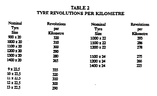
M = tyre revolutions per kilometre determined from the Table 2 (in this Section) which gives the standard number of revolutions per kilometre to be adopted for tyre sizes used in 'Road Train’ operations.
T = maximum engine net torque in Newton metres; and
g = maximum grade expressed as a percentage. For normal 'Road Train’ operations, a value of 15% (starting ability 10% + operating gradient 5%) is used.
44.2.3.3.1.2. For 'Road Trains’ operating with a 'Gross Combination Mass' up to 38 tonnes, the maximum gross ‘Road Train' mass for the drawing vehicle shall be determined in accordance with Clause 44.2.3.3.1.1.1.
44.2.3.3.2. Maximum road speed capabilities of drawing vehicle
44.2.3.3.2.1. The maximum road speed capability of a drawing vehicle shall not be in excess of 85km/h.
44.2.3.3.2.2. The maximum road speed capability shall be calculated by the formula

Where:
L = maximum revolutions per minute at which minimum engine power is developed;
A - overall gear reduction between engine and drive wheels giving highest road speed; and
M = tyre revolutions per kilometre determined from Table 2 (Clause 44.2.3.3.1.) which gives the standard number of revolutions per kilometre to be adopted for tyre sizes used in `Road Train' operation.
44.2.3.3.3. Drive `Axle' on drawing vehicle
The drawing vehicle used in a `Road Train’ with a ‘Gross Combination Mass’ in excess of 42 tonnes shall have at least a tandem driven rear 'Axle Group’.
If internal differentials are fitted then they shall be of the positive locking type.
44.2.3.3.4. Tracking Requirements for 'Road Trains'
All units incorporated in a `Road Train’ travelling on a level, smooth surface shall track in the path of the drawing vehicle without shifting or swerving more than 100 mm either side of the path of the drawing vehicle when it is travelling in a straight line.
44.2.3.4. Additional Headlamps for 'Road Trains’
44.2.3.4.1. Additional headlamps may be affixed to the front of the drawing vehicle of a `Road Train’ provided that the total number of headlamps does not exceed 6 and the additional .headlamps are automotive type main beam lamps which are so fitted and of such a type that:
44.2.3.4.1.1. they are not higher than 1,400 mm above the ground;
44.2.3.4.1.2. they are capable of showing a white light only and projecting the main beam in front of the vehicle; and
44.2.3.4.1.3. they are so connected electrically with the normal headlamps that they will be extinguished when the headlamps are in the dipped position and such that they can also be extinguished separately.
44.2.3.5. 'Axle Group' Spacing in 'Road Trains’
44.2.3.5.1. A `Single Axle' with dual tyres shall be spaced not less than 5.0 m from the centre of an adjacent 'Tandem Axle Group'.
44.2.3.5.2. A `Single Axle’ with dual tyres shall be spaced not less than 5.0 m from the centre of an adjacent `’Triaxle Group’.
44.2.3.5.3. Adjacent pairs of `Tandem Axle Groups' shall be spaced not less than 6 m between the centres of the ‘Axle Groups’.
44.2.3.5.4. A ‘Tandem Axle Group’ and an adjacent ‘Triaxle Group' shall be spaced not less than 7.0 m between the centres of the ‘Axle Groups'.
44.2.3.5.5. Adjacent ‘Triaxle Groups' are not permitted
44.2.4. COMBINATIONS OF TRAILERS AND MOTOR VEHICLES (other than `Road Trains’)
44.2.4.1. General Attachment Requirements
44.2.4.1.1. A trailer other than a `Semi-trailer’ shall be securely attached to the drawing vehicle by a suitable 'Coupling' so fitted as to prevent as far as possible lateral swing of the trailer when the drawing vehicle and trailer are in motion.
44.2.4.1.2. A ‘Semi-trailer’ shall be securely attached to the ‘Prime Mover'.
44.2.4.2. `Couplings' and 'Drawbars' for vehicles other than passenger can (MA), forward-control passenger vehicles (MB), ORPV (MC) and L-group vehicles
44.2.4.2.1. When a trailer other than a `Semi-trailer’ or ‘Pole -type Trailer’ is attached by means of a ‘Coupling’ and 'Drawbar' which controls the movement of such trailer to any drawing vehicle, the ‘Coupling' and ‘Drawbar’ shall be constructed and fitted so that
44.2.4.2.1.1. it will permit an adequate amount of angular movement between the alignment of the drawing vehicle and trailer;
44.2.4.2.1.2. the strength of the `Coupling' and ‘Drawbar’ is sufficient to prevent the trailer from becoming separated;
44.2.4.2.1.3. the 'Coupling' is equipped with a manually operated positive locking mechanism so constructed as to prevent accidental disengagement of the unit whilst in operation;
44.2.4.2.1.4. the positive locking mechanism of Clause 44.2.4.2.1.3 shall be so designed that it can be disconnected regardless of the angle of the trailer to the drawing vehicle; and
44.2.4.2.1.5. the brackets or other means of securing the front portion of the `Coupling' to the drawing vehicle and the rear portion of the ‘Coupling' and the ’Drawbar' to the trailer are of sufficient strength to prevent the trailer from becoming separated, and are securely attached to a substantial portion of the frame or framework of the respective vehicle.
44.2.4.2.1.6. The bumper bars of vehicles shall not be used as points of attachment for ‘Couplings’.
44.2.4.3. Safety Connections for Vehicles other than Passenger Can (MA), Forward-control Passenger Vehicles (MB), Of-road Passenger Vehicles (MC) and L-Group vehicles
44.2.4.3.0. The provisions of Clauses 44.2.4.3.1 and 44.2.4.3.2 shall not apply to trailers (except rigid ‘Drawbar’ ‘Pig Trailers') fitted with an 'Emergency Brake System' in accordance with ADR 38/... "Trailer Brake Systems”.
44.2.4.3.1. In addition to the 'Coupling' prescribed and fitted in accordance with the requirements Clause 44.2.4.2, there shall be affixed to a substantial portion of the drawing vehicle and to the frame or other substantial portion of the trailer a safety connection consisting of a chain or chains, cable or cables, or other non-rigid connection(s) which will hold in tow the trailer in the event of failure or accidental detachment of the 'Coupling'.
44.2.4.3.2. The safety connection shall be so connected and fixed that:
44.2.4.3.2.1. it is not liable to accidental disconnection and permits all normal angular movements of the 'Coupling' without more slack than is necessary; and
44.2.4.3.2.2. it will prevent the forward end of the `Drawbar' from striking the ground in the event of accidental disconnection of the `Coupling'.
44.2.4.3.3. Specifications for Safety Chain
44.2.4.3.3.1. The safety chain shall:
44.2.4.3.3.1.1. for a trailer less than 2.5 tonnes ‘Aggregate Trailer Mass’, shall be of mild steel and comply with the provisions of Australian Standard 1872-1976 “Safety Chains for Trailers and Caravans” ;
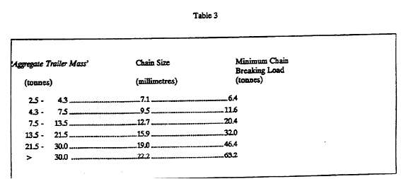
44.2.4.3.3.1.2. for a trailer of 2.5 tonnes or more `Aggregate Trailer Mass’, shall be made from steel of a minimum 800 MPa breaking stress and conform to the mechanical properties of Grade T chain as specified in Australian Standard 2321-1979 'Short Link Chain for Lift Purposes”#; and be of a size corresponding with the ‘Aggregate Trailer Mass' of the trailer in Table 3.
44.2.4.3.4. A rigid 'Drawbar' 'Pig Trailer’ which has an 'Aggregate Trailer Mass' of 2.5 tonnes or more shall be fitted with 2 safety chains for connection to the towing vehicle.
44.2.4.3.5. Safety chains shall be permanently attached to the trailer so that the method of attachment does not involve welding or deformation. Shackles are not permitted. The point(s) of attachment to the trailer shall be as near as practicable to the 'Coupling' and where 2 points are required they shall be mounted one on either side of the ‘Drawbar’.
44.2.4.4. 'Couplings', ‘Towbars’, ‘Drawbars' and Safety Connections for Passenger Cars (MA), Forward-control Passenger Vehicles (MB) and Off-road Passenger Vehicles (MC)
44.2.4.4.1. The term 'passenger car' as used in this Section includes forward-control passenger vehicles (MB) and Off-road Passenger Vehicles (MC.)
44.2.4.4.2. ‘Coupling’ for passenger cars (MA, MB, MC)
44.2.4.4.2.1. The trailer shall be securely attached to the drawing vehicle by a ‘Coupling’. When viewed in plan, the centre of the 'Coupling' shall lie on the longitudinal centreline of the drawing vehicle.
44.2.4.4.2.2. The 'Coupling' shall be constructed and fitted in such a manner that.
44.2.4.4.2.2.1. it will permit an adequate amount of angular movement between the drawing vehicle and the trailer;
44.2.4.4.2.2.2. accidental disengagement whilst in operation is prevented; and
44.2.4.4.2.2.3. it has sufficient strength to prevent separated in service.
44.2.4.4.2.3. To establish the strength of the 'Coupling' the following tests should be carried out
44.2.4.4.1.3.1. When installed in its design configuration, the 'Coupling' shall withstand the following loads without incurring loss of attachment or any distortion or failure which would affect the safe towing of a trailer:
Longitudinal tension and compression - 3 x the 'Gross Trailer Mass’ for which the ‘Coupling’ is designed
Transverse thrust - 1 x the 'Gross Trailer Mass’ for which the ‘Coupling’ is designed.
Vertical tension and compression - 13 x the 'Gross Trailer Mass' for which the ‘Coupling’ is designed.
44.2.4.4.2.4. The ball of any ball 'Coupling’ fitted for use with a trailer having a 'Gross Trailer Mass' not exceeding 2,270 kg shall have a spherical working surface of 50 mm nominal diameter and shall be legibly and indelibly marked with the mark '50' in characters not les than 5 mm high. The location of the marking shall be such that it does not interfere with the normal functioning of the ball.
44.2.4.4.2.5. The body of a ball 'Coupling' fitted to a trailer having a 'Gross Trailer Mass’ not exceeding 2,270 kg, shall be legibly and indelibly marked with the following information:
44.2.4.4.2.5.1. the manufacturer's name or trade mark,
44.2.4.4.2.5.2. the mark '50’ to indicate the size of ball to which it is designed to be attached, and
44.2.4.4.2.5.3. the 'Gross Trailer Mass' for which the 'Coupling' body is designed (in kg).
44.2.4.4.2.5.4. Such markings shall be in characters not less than 5 mm high and shall be located in a suitable prominent position on the 'Coupling' body.
44.2.4.4.2.6. 'Couplings' other than ball coupling fitted to a trailer shall be legibly and indelibly marked with
44.2.4.4.2.6.1. the manufacturer's name or trade mark; and
44.2.4.4.2.6.2. the 'Gross Trailer Mass' for which the ‘Coupling’ is designed (in kg).
44.2.4.4.2.6.3. Such markings shall be in characters not less than 5 mm high.
44.2.4.4.3. Not used
44.2.4.4.4. ‘Towbars’ for passenger cars (MA, MB, MC)
44.2.4.4.4.1. The ‘Towbar’ shall
44.2.4.4.4.1.1. be of sufficient strength to withstand the loads imposed by the trailer;
44.2.4.4.4.1.2. be securely attached to a substantial portion of the structure of the drawing vehicle; and
44.2.4.4.4.1.3. be equipped with attachments for safety connections. The attachments shall be of sufficient strength to withstand the loads imposed and prevent the front end of the 'Drawbar' striking the ground in the event of failure or accidental detachment of the 'Coupling'.
44.2.4.4.4.2. To establish the strength of a 'Towbar', the following tests shall be carried out: When mounted with its designed attachments to the vehicle for which it is designed, or a structure representative of the vehicle, the ‘Towbar' and the vehicle structure shall withstand the following loads
without incurring loss of attachments or any distortion or failure which will affect the safe towing of the trailer:
Longitudinal tension and compression - 1.5 x the ‘Towbars’ specified towing capacity
Transverse thrust – 0.5 x the 'Towbar's' specified towing capacity
Vertical tension and compression – 0.5 x the 'Towbar's' specified towing capacity
44.2.4.4.4.3. To establish the strength of the attachments provided on the ‘Towbar' for safety connections, the following tests shall be carried out:
The safety attachments shall withstand the following loads without failure:
Longitudinal tension – The 'Towbar's' specified towing capacity.
Vertical load - 0.5 x the 'Towbar's' specified towing capacity.
44.2.4.4.4.4. The ‘Towbar' shall clearly and permanently display the following information when fitted to the vehicle:
44.2.4.4.4.4.1. the ‘Towbar' manufacturer's name or trade marl
44.2.4.4.4.4.2. the 'make and model' shown on the 'Compliance Plate' fitted to the vehicle to which it is designed or manufacturer's part number, and
44.2.4.4.4.4.3. the towing capacity expressed in kg. The towing capacity shall be the `Gross Trailer Mass’ for which the `Towbar' is designed.
44.2.4.4.4.5. A Towbar' bearing reference to manufacture for a particular ‘make and model’ shall be fitted only to a vehicle of that make and model classification, or any subsequent model variant, provided that the ‘Towbar' attachment points remain unchanged.
44.2.4.4.4.6. The towing capacity of a `Towbar' fitted to a vehicle as displayed on the ‘Towbar' shall not exceed 1.5 times the 'Unladen Mass’ for an MA vehicle or the 'Unladen Mass' for an MB or MC vehicle, or the manufacturer's recommended towing capacity, whichever is the least
44.2.4.4.5. 'Drawbars' for passenger cars (MA, MB, MC)
The 'Drawbar' shall:
44.2.4.4.5.1. be of sufficient strength to prevent the trailer from becoming separated from the ‘Coupling’
44.2.4.4.5.2. be securely attached to a substantial portion of the trailer, and
44.2.4.4.5.3. be equipped with attachments for safety connections. The attachments shall be of sufficient strength to withstand the loads imposed and prevent the front end of the ‘Drawbar' striking the ground in the event of failure or accidental detachment of the `Coupling'.
44.2.4.4.5.4. To establish the strength of a `Drawbar' the following tests should be carried out: When attached to a frame representing the trailer frame in its design configuration, the `Drawbar' shall withstand the following loads without incurring loss of attachment or any distortion or failure which would affect the safe towing of the trailer:
Longitudinal tension and compression – 1.5 x the ‘Gross Trailer Mass’
Transverse thrust – 0.5 x the `Gross Trailer Mass’.
Vertical tension and compression – 0.5 x the 'Gross Trailer Mass’.
44.2.4.4.5.5. To establish the strength of attachments provided on the 'Drawbar' for safety connections, the following tests should be carried out:
The safety attachments shall withstand the following loads without failure:
Longitudinal tension - The 'Gross Trailer Mass'.
Vertical load – 0.5 x the `Gross Trailer Mass'.
44.2.4.4.6. Not used
44.2.4.4.7. Safety connections for passenger cars (MA, MB and MC)
44.2.4.4.7.1. Safety connections shall be capable of supporting a load equal to or greater than the trailer's 'Gross Trailer Mass'.
44.2.4.4.7.2. Safety chain fitted to any trailer having a `Gross Trailer Mass' not exceeding 2,270 kg shall be marked to indicate that it was manufactured to comply with Australian Standard 1872-1976 “Safety Chains for Trailers and Caravans “ . The chain size designation marking shall be consistent with the `Manufacture's' `Gross Trailer Mass’. No welding operation shall be performed on the chain subsequent to its manufacture.
44.2.4.4.7.3. Attachment of safety connections to both 'Towbar' and ‘Drawbar’ shall be separate from the `Coupling' and its fasteners.
44.2.4.5. 'Couplings', `Towbars' and Safety Connections for L-Group Vehicles
44.2.4.5.0. The term 'motor cycle' as used in this Section includes all L-Group vehicles.
44.2.4.5.1. Motor cycles which are equipped to tow trailers and trailers which are towed by motor cycles shall comply with the special conditions of this Section.
44.2.4.5.2. General
44.2.4.5.2.1. `Couplings' fitted to motor cycles and trailers having 2 or more wheels laterally disposed about the longitudinal axis of the trailer, where the trailer is not constructed to lean with the drawing vehicle shall permit a degree of movement about the combination's longitudinal, vertical and lateral axes.
44.2.4.5.2.2. 'Couplings' fitted to motor cycles and trailers, other than referred to in Clause 44.2.4.5.2.1 shall permit a degree of angular movement about the combination's lateral and vertical axes only
44.2.4.5.2.3. When unladen or when laden so that the load is evenly distributed along the length of the trailer's cargo space, and with the trailer in a horizontal position, the centre of mass of the trailer shall be forward of the effective axle centre such that there is a downward force at the `Coupling' which is not less than 2% of the `Gross Trailer Mass' and not more than 5% of it.
44.2.4.5.2.4. When laden to `Gross Trailer Mass', and with the ‘Drawbar’ in it’s design position, the top of the defined cargo space of a trailer to which Clause 44.2.4.5.2.1 applies shall be of a height not greater than the difference between the track width of the trailer and the height of the floor of the cargo space.
44.2.4.5.2.5. Wheels and tyres intended for industrial applications shall not be fitted to any trailer used with a motor cycle having a maximum design speed exceeding 15 km/h.
44.2.4.5.3. 'Towbars' and associated 'Coupling' Components Fitted to Motor Cycles
44.2.4.5.3.0. Any 'Towbar’ or associated 'Coupling' component fitted to a motor cycle
shall:
44.2.4.5.3.1. be of sufficient strength to withstand the loads imposed by trailers having a ‘Gross Trailer Mass’ of not less than the 'Unladen Mass' of the motor cycle;
44.2.4.5.3.2. be firmly attached to a substantial part of the structure of the motor cycle;
44.2.4.5.3.3. be equipped with attachments for safety connections. The attachments shall be of sufficient strength to withstand the loads imposed and prevent the forward end of the ‘Drawbar’ striking the ground in the event of failure or accidental detachment of the `Towbar' or `Coupling' when the motor cycle is upright; and
44.2.4.5.3.4. clearly and permanently display the manufacturer's name or trademark and the towing capacity expressed in kg. For the purposes of this Clause the towing capacity shall be the 'Gross Trailer Mass’ for which the 'Towbar' or 'Coupling' is designed.
44.2.4.5.3.5. Such marking shall be in characters not les than 5 mm high and shall be located is a prominent position on the `Towbar'.
44.2.4.5.3.6. If the components bear references to a particular motor cycle ‘make and model’ they shall be fitted only to a vehicle of that make and model classification, or any subsequent model variant provided that the `Towbar' attachment points remain unchanged.
44.2.4.5.3.7. To establish the strength of a 'Towbar' or an associated ‘Coupling’ component, the following tests shall be carried out:
44.2.4.5.3.7.1. When mounted with its designed attachments to the vehicle for which it is designed, or a structure representative of the vehicle, the component and the vehicle structure shall withstand the following loads without incurring loss of attachment or any distortion or failure which will affect the safe towing of the trailer:
Longitudinal tension and compression: 750% of the specified towing capacity
Transverse thrust: 50% of the specified towing capacity, and
Vertical tension and compression: 50% of the 'Towbar’s’ specified towing capacity
44.2.4.5.3.7.2. To establish the strength of the attachments provided on the 'Towbar' or any other safety connections, the following tests shall be carried out:
The safety attachments shall withstand the following failure tests:
Longitudinal tension - 150% of the specified towing capacity;
Vertical load - 50% of the specified towing capacity.
44.2.4.5.4. `Drawbars' and Associated ‘Coupling’ Components Fitted to the Trailer
44.2.4.5.4.0. Any ‘Drawbar’ or `Coupling' component fitted to a trailer that is intended for use with a motor cycle shall:
44.2.4.5.4.1. be of sufficient strength to prevent the trailer from becoming separated from the motor cycle;
44.2.4.5.4.2. be securely attached to a substantial portion of the trailer; and
44.2.4.5.4.3. be equipped with attachments for safety connections. The attachments shall be of sufficient strength to withstand the load imposed and prevent the forward end of the `Drawbar' striking the ground in the event of failure or accidental detachment of the `Coupling' when the towing motor cycle is upright.
44.2.4.5.4.4. To establish the strength of a trailer ‘Drawbar’ or 'Coupling' component the following tests should be carried out:
When attached to a frame representing the trailer frame in its design configuration, the component shall withstand the following loads without incurring loss of attachment or any distortion or failure which would affect the safe towing of a trailer:
Longitudinal tension and compression - 150% of the 'Gross Trailer Mass’;
Transverse thrust - 50% of the 'Gross Trailer Mass’
Vertical tension and compression - 50% of the ‘Gross Trailer Mass’
44.2.4.5.4.5. To establish the strength of the attachments provided in association with safety connections, the following tests shall be carried out:
The safety attachment shall withstand the following failure tests:
Longitudinal tension – 150% of the ‘Gross Trailer Mass’
Vertical load – 50% of the ‘Gross Trailer Mass’
44.2.4.5.4.6. When viewed in plan, the centre of the trailer `Coupling' shall lie on the longitudinal centreline of the trailer.
44.2.4.5.4.7. The `Coupling' shall be constructed and fitted in such a manner that accidental disengagement whilst in operation is precluded and when motor cycle and trailer are connected it has sufficient strength to prevent the drawing vehicle and the trailer from becoming separated in service.
44.2.4.5.4.8. The `Coupling' shall be legibly and indelibly marked with the manufacturer's name or trademark and the maximum ‘Gross Trailer Mass’ of trailers for which the ‘Coupling’ body is designed (in kg). Such markings shall be in characters not less than 5 mm high and shall be located in a prominent position on the ‘Coupling’ body.
44.2.4.5.5. Safety Connections for Motor Cycles
44.2.4.5.5.1. Safety connections shall be capable of supporting a load equal to or greater than the `Gross Trailer Mass'.
44.2.4.5.5.2. Safety chain shall comply with the Australian Standard referred to in Clause 44.2.4.4.7.2, or other `Approved’ standard and be marked accordingly. The capacity of the chain should not be less than the trailer’s `Gross Trailer Mass' rating. No welding operation shall be performed on any chain subsequent to its fitment...
44.2.4.5.5.3. Attachment of safety connections to both `Towbar' and `’Drawbar’ shall be separate from the `Coupling' components and their fasteners.
44.2.4.5.5.4. Safety connections shall be so designed as to prevent the `Drawbar' or attachments interfering with the rotation of the rear wheel.
44.2.5. 'POLE-TYPE TRAILERS' AND THEIR DRAWING VEHICLES - SPECIAL LIGHTING REQUIREMENTS
44.2.5.1. On every 'Pole-type Trailer' there shall be the following:
44.2.5.1.1. on each side of the rearmost bolster, one `Side Marker Lamp’; and
44.2.5.1.2. one front reflex reflector, non triangular on each side of the front facing of the foremost bolster.
44.2.5.2. Drawing Vehicles for ‘Pole-type Trailers’
44.2.5.2.1. On every motor vehicle fined with one or more bolster, i.e. a motor vehicle designed to draw a 'Pole-type Trailer', there shall be the following:
44.2.5.2.1.1. an each side of the rearmost bolster, one 'Side Marker Lamp'; and
44.2.5.2.1.2. one front reflex reflector, non-triangular on each side of the front facing section of the foremost bolster.
44.2.6. LIQUEFIED PETROLEUM GAS (LPG) FUELLED VEHICLES
44.2.6.0. All motor vehicles manufactured to use LPG as a fuel shall meet the following requirements.
44.2.6.1. The LPG fuel system shall at least meet either
44.2.6.1.1. the Australian Standard 1425-1982 "SAA Code for the Use of LP Gas in internal Combustion Engines" including Amendments 1 & 2; or
44.2.6.1.2. the Australian Standard 1425-1989 "SAA Code for the use of LP Gas in Internal Combustion Engines” and the Australian Standard 3509-1988 “LP Gas Fuel Vessels for Automotive Use”
44.2.6.2. The vehicle shall be clearly and permanently marked either on the LPG storage cylinder(s) or its protective cover(s), or in a conspicuous position within the engine bay, with the following:
44.2.6.2.1. a statement that the LPG fuel system has been installed in accordance with we of the documents referred to in Clause 44.2.6.1;
44.2.6.2.2. the identification of the licensed or approved person or organisation which installed the LPG fuel system; and
44.2.6.2.3. the date of installation.
44.2.6.3. The vehicle, to indicate that it is equipped to use LPG as a fuel, shall carry affixed to the front and rear registration plates. an external label of durable material conforming with at least the following specifications:
44.2.6.3.1. size, not less than 25 mm square; and
44.2.6.3.2. colour, reflective red conforming to Australian Standard 1742-1975 "Manual of Uniform Traffic Control Devices" Appendix C, Class 2.
44.2.7. EMERGENCY COMMUNITY SERVICE VEHICLES - LAMPS
44.2.7.1. Any motor vehicle used as an ambulance may be equipped with a lamp or lamps which when lighted show the word "AMBULANCE" or illuminate a sign recognized as that of an ambulance service.
44.2.7.2. Flashing warning lamps
Vehicles operated by ambulance, fire fighting and police authorities or organisations providing emergency community services which may require priority travel when engaged on emergency work may be equipped with a flashing lamp or lamps. Such lamps shall meet the following provisions:
44.2.7.2.1.1. At least one lamp shall be mounted on top of the vehicle and when lighted, shall be visible in normal daylight up to a distance of not less than 200 metres to vehicles approaching from any direction.
44.2.7.2.1.2. The colour shall be:
44.2.7.2.1.2.1. blue in the case of police vehicles;
44.2.7.2.1.2.2. red in the case of ambulance or fire fighting vehicles; or
44.2.7.2.1.2.3. amber in the case of other emergency community service vehicles.
44.2.7.2.1.3. In the case of vehicles permitted to display flashing warning lamps, additional lamps may be mounted in any position on the vehicle visible either directly or indirectly to the driver when seated in the normal driving position.
44.2.7.2.1.4. All flashing warning lamps fitted to a motor vehicle and under the provisions of this Clause shall be of the same colour.
44.2.8. MOTORHOMES AND 'CARAVANS’
44.2.8.1. Doors
Every motor vehicle (motorhome) or trailer (‘Caravan') equipped with fuel burning (cooking) facilities or living or sleeping accommodation shall have only outward-opening or sliding doors. At least one such door shall be located on the left-hand side or at the rear.
44.2.8.2. Liquefied Petroleum Gas Equipment
Unless otherwise 'Approved', liquefied petroleum gas installations in motorhomes and ‘Caravans’ shall comply with the requirements of "Code Governing the Installation in Caravans of Liquefied Petroleum Gas Equipment and Appliances”, issued by the Australian Liquefied Petroleum Gas Association.
44.2.8.3. Fire Extinguisher
Motorhomes and ‘Caravans’ shall be provided with a fire extinguisher(s) selected and located in accordance with the Australian Standard referred to in Clause 44.2.2.5. Each extinguisher shall be of the dry chemical or halogenated hydrocarbon (B.C.F. or B.T.M. type).
