
Vehicle Standard (Australian Design Rule 35/06 – Commercial Vehicle Brake Systems) 2018
originally made under the Motor Vehicle Standards Act 1989 and continued in force under the Road Vehicle Standards Act 2018
Compilation No. 2
Compilation date: 29/09/2023
Includes amendments up to: Vehicle Standard (Australian Design Rule) Safer Freight Vehicles Amendment No 1 2023
Prepared by: Vehicle Safety Policy and Partnerships, Department of Infrastructure, Transport, Regional Development, Communications and the Arts
About this compilation
This compilation
This is a compilation of the Vehicle Standard (Australian Design Rule 35/06 – Commercial Vehicle Brake Systems) 2018 that shows the text of the law as amended and in force on 29/09/2023 (the compilation date).
The notes at the end of this compilation (the endnotes) include information about amending laws and the amendment history of provisions of the compiled law.
Uncommenced amendments
The effect of uncommenced amendments is not shown in the text of the compiled law. Any uncommenced amendments affecting the law are accessible on the Register (www.legislation.gov.au). The details of amendments made up to, but not commenced at, the compilation date are underlined in the endnotes. For more information on any uncommenced amendments, see the Register for the compiled law.
Application, saving and transitional provisions for provisions and amendments
If the operation of a provision or amendment of the compiled law is affected by an application, saving or transitional provision that is not included in this compilation, details are included in the endnotes.
Modifications
If the compiled law is modified by another law, the compiled law operates as modified but the modification does not amend the text of the law. Accordingly, this compilation does not show the text of the compiled law as modified. For more information on any modifications, see the Register for the compiled law.
Self‑repealing provisions
If a provision of the compiled law has been repealed in accordance with a provision of the law, details are included in the endnotes.
CONTENTS
1. LEGISLATIVE PROVISIONS.....................................4
2. FUNCTION....................................................4
3. APPLICABILITY...............................................4
4. DEFINITIONS..................................................7
5. DESIGN REQUIREMENTS.......................................4
6. PERFORMANCE REQUIREMENTS..............................21
7. GENERAL TEST CONDITIONS..................................21
8. PARTICULAR TEST CONDITIONS...............................24
9. ALTERNATIVE STANDARDS...................................30
APPENDIX 1.........................................................38
APPENDIX 2.........................................................39
APPENDIX 3.........................................................42
APPENDIX 3 – Annex 1................................................48
APPENDIX 3 – Annex 2................................................58
APPENDIX 3 – Annex 3................................................61
APPENDIX 4.........................................................63
APPENDIX 5.........................................................65
ENDNOTES.........................................................66
- LEGISLATIVE PROVISIONS
- Name of Standard
- This standard is the Vehicle Standard (Australian Design Rule 35/06 – Commercial Vehicle Brake Systems) 2018.
- This standard may also be cited as Australian Design Rule 35/06 – Commercial Vehicle Brake Systems.
- FUNCTION
- The function of this standard is to specify braking requirements on commercial vehicles and large passenger vehicles to ensure safe braking under normal and emergency conditions.
- APPLICABILITY
- This vehicle standard applies to category LEG, MB, MC, MD, ME, NA, NB and NC vehicles; from the dates set out in clauses 3.1.1 to 3.1.4 and the table under clause 3.11 below.
- 1 July 2019 for all new model category LEG, MB, MC and NA vehicles.
- 1 November 2020 for all new model category MD, ME, NB and NC vehicles.
- 1 January 2022 for all category MD, ME, NB and NC vehicles.
- There is no mandatory application date for all other vehicles. They may comply with this vehicle standard, or continue to comply with earlier versions of this vehicle standard, as applicable for the particular vehicle category.
- For the purposes of clauses 3.1.1 and 3.1.2, a “new model” is a vehicle model first produced with a ‘Date of manufacture’ on or after the agreed date in each clause respectively.
- Category MB, MC or NA vehicles complying with the requirements of ADR 31/… will be accepted as complying with this standard.
- Category LEG vehicles that are fitted with a single foot pedal controlling both front and rear service brakes must comply with all requirements of this standard applicable to category NA vehicles. Other category LEG vehicles must comply with ADR 33/…
- This standard does not apply to combinations of drawing vehicle and trailer.
- A vehicle comprising two or more non-separable articulated units must be considered as a single vehicle for the purposes of this standard.
- Category MB, MC and NA vehicles certified to this standard must also be certified to ADR 88/… – Electronic Stability Control (ESC) Systems and ADR 89/… – Brake Assist Systems (BAS).
- Category NA vehicle types approved to the United Nations Regulation No. 13 – UNIFORM PROVISIONS CONCERNING THE APPROVAL OF VEHICLES OF CATEGORIES M, N AND O WITH REGARD TO BRAKING, incorporating the 11 series of amendments, will be deemed to comply with this standard.
- Category MD, ME, NB and NC vehicle types approved to the United Nations Regulation No. 13 – UNIFORM PROVISIONS CONCERNING THE APPROVAL OF VEHICLES OF CATEGORIES M, N AND O WITH REGARD TO BRAKING, incorporating the 11 series of amendments, will be deemed to comply with this standard, provided that the requirements of clauses 5.3.5, 5.3.6, 5.3.7, 5.8.1.1, 5.8.2 and 8.12.6.2 (where applicable) are met.
- Vehicles certified to comply with the Australian Design Rule 35/07 – Commercial Vehicle Brake Systems, or a later version, are not required to comply with this rule.
- Applicability Table
Vehicle Category | ADR Category Code | UN Category Code* | Manufactured on or After | Acceptable Prior Rules |
Moped 2 wheels | LA | L1 | not applicable | |
Moped 3 wheels | LB | L2 | not applicable | |
Motor cycle | LC | L3 | not applicable | |
Motor cycle and sidecar | LD | L4 | not applicable | |
Motor tricycle | LE | L5 | | |
| LEM | | not applicable | |
| LEP | | not applicable | |
| LEG | | 1 July 2019** | see clause 3.1.4 |
Passenger car | MA | M1 | not applicable | |
Forward-control passenger vehicle | MB | M1 | 1 July 2019** | see clause 3.1.4 |
Off-road passenger vehicle | MC | M1 | 1 July 2019** | see clause 3.1.4 |
Light omnibus | MD | M2 | | |
up to 3.5 tonnes ‘GVM’ and up to 12 seats | MD1 | | 1 November 2020** | /02, /03, /04, /05 |
up to 3.5 tonnes ‘GVM’ and more than 12 seats | MD2 | | 1 November 2020** | /02, /03, /04, /05 |
over 3.5 tonnes and up to 4.5 tonnes ‘GVM’ | MD3 | | 1 November 2020** | /02, /03, /04, /05 |
over 4.5 tonnes and up to 5 tonnes ‘GVM’ | MD4 | | 1 November 2020** | /04, /05 |
Heavy omnibus | ME | M3 | 1 November 2020** | nil |
Light goods vehicle | NA | N1 | 1 July 2019** | see clause 3.1.4 |
Medium goods vehicle | NB | N2 | | |
over 3.5 tonnes up to 4.5 tonnes ‘GVM’ | NB1 | | 1 November 2020** | /04, /05 |
over 4.5 tonnes up to 12 tonnes ‘GVM’ | NB2 | | 1 November 2020** | /04, /05 |
Heavy goods vehicle | NC | N3 | 1 November 2020** | nil |
Very light trailer | TA | O1 | not applicable | |
Light trailer | TB | O2 | not applicable | |
Medium trailer | TC | O3 | not applicable | |
Heavy trailer | TD | O4 | not applicable | |
* The category code may also be in the format L1, L2, L3 etc. ** See clause 3.1.
- DEFINITIONS
- For vehicle categories, definitions and meanings used in this standard, refer to:
- Vehicle Standard (Australian Design Rule Definitions and Vehicle Categories) 2005;
- APPENDIX 1 of this standard;
- Definitions in clause 1 of APPENDIX 3 of this standard; and
- Definitions in clause 1 of APPENDIX 5 of this standard.
- DESIGN REQUIREMENTS
- ‘Service Brake System’
- The vehicle must be equipped with a ‘Service Brake System’ operable on all road wheels through the medium of a single ‘Control’ so placed that it can be actuated by the operator from the normal driving position.
- The vehicle must have one or more service brake failure ‘Visible Indicators’ meeting the requirements of clause 5.2.
- Where separate methods of actuation are provided for any of the functions of the brake system, the actuation of one function must not cause the operation of another function.
- The ‘Service Brake System’ must incorporate devices, which automatically compensate for any increased movement of its components arising from wear. Such devices must themselves contain provision for securing them throughout their working range in any position to which they adjust.
- Category MD4, ME, NB or NC vehicles, with not more than four axles, must be equipped with an ‘Antilock System’.
- Each vehicle that is equipped with an ‘Antilock System’, must meet the requirements of APPENDIX 2.
- Except as set out in clause 5.1.7.1 below, a manual device must not be provided to disconnect or change the control mode of the ‘Antilock System’ of a category MD4, ME, NB or NC vehicle.
- Category NB or NC vehicles designed for off-road use (refer APPENDIX 1 for definition), may be fitted with a device to disconnect or change the control mode of the ‘Antilock System’, where such a device meets the requirements of APPENDIX 2.
- Except as set out in clauses 5.1.8.1, 5.1.8.2 and 5.1.8.3 below, a ‘Vehicle Stability Function’ including both ‘Rollover Control’ and ‘Directional Control’ must be fitted to each of the following:
- category ME vehicles;
- category NC ‘Prime Movers’;
- category NC ‘Cab-over engine vehicles’ with a ‘Wheelbase’ not exceeding 4.5 metres and all other category NC vehicles with a ‘Wheelbase’ not exceeding 5.0 metres.
The ‘Vehicle Stability Function’ must be operational over the full speed range of the vehicle, except; at vehicle speeds less than 20 km/h, when it has been manually or automatically disabled (refer clauses 2.3 and 2.4 of APPENDIX 3), the vehicle is being driven in reverse, or during system initialisation.
- Any ‘Articulated Omnibus’ or ‘Route Service Omnibus’, need not be equipped with a ‘Vehicle Stability Function’.
- Any category NC vehicle with four or more ‘Axles’, need not be equipped with a ‘Vehicle Stability Function’.
- Any vehicle which is ‘designed for off-road use’ (refer APPENDIX 1 for definition), need not be equipped with a ‘Vehicle Stability Function’.
- Each vehicle required by clause 5.1.8 above to be equipped with a ‘Vehicle Stability Function’, must meet the requirements of APPENDIX 3. Other vehicles may be certified to the requirements of APPENDIX 3, clauses 2 and 3, at the discretion of the ‘Manufacturer’.
- All components and devices in the ‘Brake System’ must meet or exceed at least one appropriate and recognised international, national or association standard, where such standards exist, or the relevant parts thereof. ‘Recognised’ can be taken to include SA, SAE, BS, JIS, DIN, performance and design related ISO standards and UN regulations.
- Traction control systems may utilize part of the ‘Service Brake System’ provided that, except for parts common to both the traction control system and the ‘Service Brake System’, the traction control system or any failure of it cannot interfere with normal braking.
- In the case of a vehicle equipped to tow a trailer which uses air at a positive pressure:
- The pressure developed at full application of the ‘Control’ of the ‘Service Brake System’, must be between 650 kPa (1.0 ‘E’) and 850 kPa (1.31 ‘E’) at the coupling head of the pneumatic ‘Control Line’ and between 650 kPa and 900 kPa at the coupling head of the ‘Supply Line’, irrespective of the load condition of the vehicle.
- Where the vehicle is also equipped with an electric ‘Control Line’, full application of the control of the ‘Service Brake System’ must provide a digital demand value corresponding to a pressure between 650 kPa (1.0 ‘E’) and 850 kPa (1.31 ‘E’) (see ISO 11992:2003, including ISO 11992‑2:2003 and its Amd.1:2007).
- The pressure developed without any application of the ‘Service Brake System’, must be between 650 kPa and 900 kPa at the coupling head of the ‘Supply Line’.
- The unladen vehicle must commence to develop a braking force on at least one ‘Axle’ of each ‘Axle Group’, before the ‘Control Signal’ at each ‘Control Line’ coupling reaches 0.154 ‘E’ (100 kPa or the equivalent digital demand value in the case of any electric ‘Control Line’).
- The requirements of parts (a) to (c) of this clause must be demonstrated to be met through testing, including at any critical or worst case load condition, at the cut-in and cut-out pressures of the energy source, with a reservoir of 0.5 litre capacity connected to the pneumatic ‘Control Line’, the energy source stopped and the ‘Supply Line’ blocked off.
- For the purpose of part (d) of this clause, an ‘Axle’ is deemed to have commenced to develop a braking force, when the total static brake torque for the axle concerned reaches the lesser of:
- 100 N.m; or
- 1 per cent of the product of the static vertical load (N) on the ‘Axle’ concerned and the rolling radius of the tyres (m) fitted to the wheels, at ‘Unladen Mass’.
- Brake line couplings must not be interchangeable and must be polarized. Couplings must comply with the requirements of AS 4945‑2000 (Commercial road vehicles - Interchangeable quick connect/release couplings for use with air-pressure braking systems).
- Where the vehicle is equipped to tow a trailer which uses air at a positive pressure, the ‘Established Retardation Coefficient’ of the ‘Service Brake System’, measured using the general test conditions of clause 7 and the particular test conditions of clause 8.13, must be between the upper and lower boundaries of Figure 1 for each value of ‘Control Signal’ used, when fully laden.
- Where the vehicle is a variant of a previously tested vehicle and the effects of the changes on braking performance are known by a test conducted on a complete vehicle, a component or a sub-assembly of components, the requirements of this clause can be met by ‘Approved’ calculations.
- The requirements relating to the figure specified in this clause 5.1.14 are applicable for vehicles with a pneumatic ‘Control Line’ only, as well as for vehicles with an additional electric ‘Control Line’. In both cases, the reference value (horizontal coordinate of the figure) will be the value of the transmitted pressure in the ‘Control Line’:
- For a pneumatic ‘Control Line’, this will be the actual pneumatic pressure in the ‘Control Line’;
- In the case of an additional electric ‘Control Line’, this will be the pressure corresponding to the transmitted digital demand value in the electric ‘Control Line’, according to ISO 11992:2003, including ISO 11992‑2:2003 and its Amd.1:2007.
- Vehicles equipped with both pneumatic and electric ‘Control Lines’ must satisfy the requirements of the figure related to both ‘Control Lines’. However, identical braking characteristic curves are not required for each of these ‘Control Lines’.
- Where the vehicle has a ‘Rated Towing Capacity’ of more than 4.5 tonnes, either:
- the vehicle must have certification which provides for the operation of trailer brakes using air at a positive pressure as described in clauses 5.1.12 and 5.1.14; or
- the ‘Manufacturer’ must supply to the ‘Administrator’ sufficient data to allow the vehicle’s ‘Service Brake System’ to be modelled under laden braking conditions.
- Provision of the data derived from the tests performed as described by clause 8.13.2 will be considered sufficient for the purposes of part (b) of this clause 5.1.15.
- Where the vehicle is a variant of a previously tested vehicle and the effects of the changes on braking performance are known by a test conducted on a complete vehicle, a component or a sub-assembly of components, the requirements of this clause can be met by ‘Approved’ calculations.
- Where the ‘Service Brake System’ incorporates a single ‘Brake Power Unit 35/...’, an ‘Audible Indicator’ must be provided which must operate at all times when the service brake failure ‘Visible Indicator’ operates as specified in clause 5.2.
- Each air reservoir in a compressed air ‘Brake System’ must be fitted with a manual condensate drain valve at the lowest point. An automatic condensate valve may be fitted provided it also drains the lowest point. The manual drain valve may be incorporated in the automatic valve.
- ‘Visible Indicator’
- The ‘Visible Indicator’ must operate whenever any of the conditions listed in clauses 5.2.2 to 5.2.4 as applicable occur while the ignition or electrical control switch is in the “engine on” position or while the engine is running.
- For a ‘Service Brake System’ incorporating a hydraulic brake circuit and no ‘Brake Power Unit 35/...’ in that hydraulic circuit, condition A or optionally condition B must be met;
Condition A
A.1 When a pressure failure occurs in any part of the ‘Service Brake System’, except for pressure failure caused by either:
A.1.1 a structural failure of a housing that is common to two or more sub-systems; or
A.1.2 failure of a component of a ‘Brake Power Assist Unit’.
A.2 In the event of such failure, the indicator operation requirement is deemed to be satisfied if the indicator operates before or upon application of:
A.2.1 a differential line pressure of not more than 1.55 MPa between the active and failed brake systems measured either at a master cylinder outlet, or at a slave cylinder outlet if the master cylinder controls a slave cylinder at a booster unit:
A.2.2 a ‘Pedal Effort 35/...’ of 225 N in the case of unassisted ‘Service Brake Systems’; or
A.2.3 a ‘Pedal Effort 35/...’ of 115 N in the case of ‘Service Brake Systems’ with a ‘Brake Power Assist Unit’.
Condition B
B.1 When a drop in the level of brake fluid occurs in the reservoir(s), either to less than the ‘Manufacturer’s’ designated minimum level or to less than 25 per cent of the reservoir(s) fluid capacity whichever is the greater volume.
B.2 In the case where a master cylinder reservoir also contains fluid for the use of a system other than the brake system, the indicator system and the reservoir must be so designed that the indicator lamp will only be activated when there are variations in the fluid level in that part of the reservoir provided exclusively for the use of the brake system.
- For a ‘Service Brake System’ incorporating one or more ‘Brake Power Units 35/...’ in any section of the ‘Service Brake System’, the ‘Visible Indicator’ must operate when the supply pressure in any one ‘Brake Power Unit 35/...’ drops to or below 65 per cent of the ‘Average Operating Pressure’.
- For vehicles equipped to tow a trailer using air at positive pressure, when the pressure in the ‘Supply Line 35/...’ drops to or below 450 kPa, the ‘Visible Indicator’ must operate as required by clause 5.2.1.
- The ‘Visible Indicator’ may also operate when the ‘Supply Line 35/...’ energy level is reduced at a rate of not less than 0.15E/sec provided that in all cases the ‘Visible Indicator’ must operate as required by clause 5.2.1 when the pressure in the ‘Supply Line 35/...’ drops to or below 450 kPa.
- The ‘Visible Indicator’ must not operate when a trailer is not connected and no other defect is present. The absence of a trailer may be determined by the pressure in the ‘Supply Line 35/...’ dropping to or below 35 kPa.
- Where the requirement of this clause 5.2 necessitates the provision of more than one system failure sensor, the sensors may be interconnected to actuate only one ‘Visible Indicator’.
- As a check of function, the ‘Visible Indicator’ must be so designed that it operates when:
- the ignition or electrical control switch is turned from the ‘engine off’ position to the ‘engine on’ position, and the engine is not operating, and (unless a failure exists in the brake system) it must not operate when the engine is running; or
- the ignition or electrical control switch is in the ‘engine start’ position, and (unless a failure exists in the brake system) it must not operate after the return of the ignition or electrical control switch to the ‘engine on’ position; or
- the ignition or electrical control switch is in a position between the ‘engine on’ position and the ‘engine start’ position, which is designated by the ‘Manufacturer’ as a check position, and (unless a failure exists in the brake system) it must not operate after the return of the ignition or electrical control switch to the “engine on” position; or
- the engine start circuit is energised and (unless a failure exists in the brake system) it must not operate when the “engine start” circuit is not energised; or
- the ignition or electrical control switch is in the “engine on” position and the ‘Parking Brake System 35/...’ is engaged for vehicles where the ‘Service Brake System’ failure ‘Visible Indicator’ and the Parking Brake indicator lamp are combined.
- For vehicles equipped with an automatic transmission, the operation as a check of indicator function is not required when the transmission control lever is in a “forward” or “reverse” drive position.
- The ‘Visible Indicator’ system must be so designed that once having become operative to signal a brake failure it must operate whenever the ignition or electrical control switch is in the “engine on” position and the fault remains uncorrected.
- The ‘Visible Indicator’ may take the form of an indicator lamp or of a mechanical signalling device.
- Where an indicator lamp is used the lamp must be labelled with at least the word “BRAKE”, or the ISO 7000 symbol (no. 0239) for “BRAKE FAILURE”, placed either directly on the lens or adjacent to it in such a way that the label is illuminated by the same light source as the lens.

ISO 7000 symbol no. 0239
- The letters of the label must be not less than 3 mm high and must be of a contrasting colour to their background when illuminated.
- If the label is directly on the lens, the colour of either the label or the lens must be red and if the label is not on the lens, the colour of the lens must be red.
- An illuminated lamp may be either steady-burning or flashing.
- Where a mechanical signalling device is used, it must display at least the word “BRAKE” in letters not less than 10 mm high when the signal is deployed. Letters and background must be of contrasting colours, one of which must be red.
- The ‘Service Brake System’ failure ‘Visible Indicator’ and its specified label or display must be totally located forward of a transverse vertical plane through the point representing the intersection of the steering wheel axis of rotation and the plane of the steering wheel, and totally within the space bounded by:
- the right-hand internal side wall;
- a vertical plane along the longitudinal centre line of the vehicle;
- a horizontal plane through a point on the lower edge of the instrument panel; and
- a horizontal plane 150 mm above the highest point on the windscreen glass.
- ‘Parking Brake System 35/...’
- The vehicle must be equipped with a ‘Parking Brake System 35/...’ such that in the applied position retention is effected by mechanical means, and the braking effect is achieved by either:
- the frictional force developed between two friction surfaces; or
- the frictional force developed between two friction surfaces, together with a ‘Parking Mechanism 35/...’.
- The parking brake ‘Control’ must be separate from the service brake ‘Control’ and incorporate a device to retain it in the “brake on” position, and it must be designed to minimise the possibility of inadvertent release of the brake. This requirement will be deemed to be satisfied if at least two separate and distinct movements are necessary to disengage the parking brake.
- The ‘Parking Brake System 35/...’ must incorporate devices which compensate for any increased movement of its components arising from wear. Such devices must themselves contain provision for securing them throughout their working range in any position to which they may be adjusted to or to which they may themselves automatically adjust.
- The ‘Control’ by which the ‘Parking Brake System 35/...’ is actuated must be located so that it is readily accessible to the driver in the normal driving position.
- On every motor vehicle equipped to tow a trailer which uses air at positive pressure the operation of the ‘Parking Brake System 35/...’ must cause the pressure in the ‘Supply Line 35/...’ to drop below 35 kPa.
- Once the ‘Supply Line 35/...’ pressure has dropped below 35 kPa in accordance with clause 5.3.5, the ‘Supply Line 35/...’ must be restored to normal when the ‘Parking Brake System 35/…’ is released.
- An additional ‘Control’ may be fitted to provide for the independent release of trailer parking brakes, provided that:
- two independent actions are required to operate this ‘Control’;
- once the ‘Supply Line 35/...’ pressure has dropped below 35 kPa in accordance with clause 5.3.5, the ‘Supply Line 35/...’ is restored to the normal condition, when the ‘Control’ is operated with the engine (or motor) running; and
- the ‘Control’ automatically resets to provide for operation of the ‘Parking Brake System 35/…’ as described in clause 5.3.5, no later than upon the next application of the ‘Control’ for the ‘Parking Brake System 35/...’.
- Parking Brake Indicator Lamp
- If the vehicle is not fitted with a ‘Spring Brake System’ or a ‘Parking Brake System 35/...’ utilizing ‘Lock Actuators’, it must be provided with a lamp which indicates that the parking brake is engaged.
- The lamp may be common with or distinct and separate from any ‘Service Brake System’ failure ‘Visible Indicator’ lamp.
- In the case of a common lamp, the lamp must be labelled with the word “BRAKE”; or the ISO 7000 symbol for “BRAKE FAILURE” - specified in clause 5.2.10.
- In the case of a distinct and separate lamp the lamp must be labelled with at least the words “PARK BRAKE” or “PARKING BRAKE”; or the ISO 7000 symbol (no. 0238) for “PARKING BRAKE”, placed either directly on the lens or adjacent to it in such a way that the label is illuminated by the same light source as the lens.

ISO 7000 symbol no. 0238
- The letters of the label must be not less than 3 mm high and must be of contrasting colour to their background when illuminated. If the label is directly on the lens, the colour of either the label or the lens must be red and if the label is not on the lens, the colour of the lens must be red.
- The parking brake indicator lamp and its specified label must be located within the space boundaries specified in clause 5.2.12.
- Secondary Brake Systems
- The vehicle must be equipped with a ‘Secondary Brake System’.
- Hydraulic ‘Service Brake Systems’ must be ‘Split Service Brake Systems’.
- If the vehicle is equipped with one or more ‘Brake Power Units 35/...’ the ‘Secondary Brake System’ must be capable of application through the medium of a ‘Control’.
- The ‘Control’ of the ‘Secondary Brake System’ must be capable of releasing and applying the secondary brake after its first application. The ‘Control’ must be so placed that it can be operated by the driver in the normal driving position.
- A ‘Secondary Brake System’ may utilise elements of the ‘Service Brake System’.
- Where the ‘Secondary Brake System’ is a ‘Spring Brake System’:
- in a single circuit ‘Service Brake System’, the energy supply system for maintaining the secondary brake in its released position must include a ‘Stored Energy’ device that does not service any other device or equipment;
- in the event of failure of the energy supply to any one circuit of a ‘Service Brake System’ employing two or more independent circuits, the energy requirements for retaining the secondary brakes in the released position must be supplied from the ‘Stored Energy’ device(s) of the other circuits or optionally from an independent ‘Stored Energy’ device; and
- with the ‘Stored Energy’ device charged to its ‘Average Operating Pressure’ it must have sufficient capacity to permit the ‘Secondary Brake System’ to be applied and released not fewer than:
- Two (2) times when the brakes are adjusted so that the distance travelled by the device which directly actuates the brake shoe or pad is a maximum; or
- Three (3) times when the brakes are adjusted to the ‘Manufacturer’ specifications.
- In a vehicle equipped with a ‘Brake Power Assist Unit’ normally supplied with high pressure fluid by an engine driven pump, a back-up system must be regarded as a ‘Secondary Brake System’ if the back-up source of power assistance is immediately energized by a pump driven independently of the vehicle engine.
- Every motor vehicle equipped to tow a trailer must be so equipped that its brake system remains operative and has the performance of the Laden Secondary Brake Test (item 7 of Table 1, or item 7A of Table 5) in the event of the trailer becoming disconnected. This protection must be automatic.
- Protection systems may vent the trailer ‘Supply Line 35/...’ but this must not commence:
- until the energy level in the ‘Supply Line 35/...’ falls below 0.54 ‘E’ (350 kPa); or
- if the ‘Supply Line 35/...’ energy level is reducing at a rate of not less than 0.15E/sec (100 kPa/sec), until the energy level in the ‘Supply Line 35/...’ falls below 0.65 ‘E’ (420 kPa).
- Every motor vehicle which provides its ‘Secondary Braking System’ by means of a ‘Split Service Brake System’ and which is equipped to tow a trailer which uses air at positive pressure, must be so equipped that the operation of the ‘Secondary Brake System’ causes a control signal proportional to the degree of braking to be present in the ‘Control Line 35/...’.
- An additional ‘Control’ may be fitted to provide for the independent application of a trailer ‘Parking Brake System 38/00’. Operation of the ‘Control’ must cause the pressure in the ‘Supply Line 35/...’ to drop below 35 kPa and remain below 35 kPa independently of the motor vehicle’s ‘Service Brake System’.
- The ‘Control’ which actuates this function must be located so that it is readily accessible to the driver in the normal driving position and, marked with the words ‘TRAILER EMERGENCY BRAKES’ and a description of how to operate the control, e.g. ‘TRAILER EMERGENCY BRAKES – PULL’. The ‘Control’ must also be marked with the words ‘NOT FOR PARKING’. The letters must be not less than 5 mm high. Letters and background must be contrasting colours, one of which must be red.
- Special provisions for all vehicles with ‘Hydraulic Brake Systems’
- In cases where the ‘Service Brake System’ incorporates a master cylinder, each service brake sub-system serviced by the master cylinder must have either:
- a reservoir which contains fluid exclusively for the use of that service brake sub-system; or
- a reservoir which contains fluid for the use of 2 or more service brake sub-systems, in which case that part of the reservoir capacity provided exclusively for the use of each service brake sub-system must be not less than the volume displaced by the master cylinder piston servicing the sub-system, during a full stroke of the piston.
- The capacity of each reservoir must be not less than the fluid displacement resulting when all the wheel cylinders or calliper pistons serviced by the reservoir move from a new-lining, fully-retracted position, as adjusted according to the ‘Manufacturer’s’ recommendations to a fully-worn, fully-applied position. For the purpose of this clause, “fully-worn, fully-applied” means that the lining is worn to whichever of the following conditions allows the greatest shoe or pad movement:
- the limit recommended by the ‘Manufacturer’;
- level with rivet or bolt heads on riveted or bolted linings;
- within 3 mm of the pad mounting surface on bonded pads; or
- within the following distance of the shoe mounting surface on bonded linings:
Nominal Bonded | Lining Thickness | Worn Thickness |
< 5 mm | | 0.8 mm |
> 5 mm | < 10 mm | 3 mm |
> 10 mm | < 13 mm | 5 mm |
>13 mm | < 19 mm | 6 mm |
>19 mm | | 7 mm |
- Each ‘Brake Power Unit 35/...’ must be provided with a reservoir of capacity not less than the total capacity of the reservoirs required under the requirements of clause 5.6.2 plus the fluid displacement necessary to charge the piston(s) or accumulator(s) provided for the purpose of storing energy.
- A statement specifying the type of fluid to be used in the brake system and displaying at least the words “WARNING. Clean filler cap before removing” must be permanently affixed, stamped, engraved or embossed with letters not less than 3 mm high, either on or partially within 150 mm of one brake fluid reservoir filler plug or cap and totally within 300 mm of all reservoir filler plugs or caps. If not stamped, engraved or embossed, the lettering must be of a contrasting colour to that of the background.
- Special provisions for systems using ‘Stored Energy’ (except ‘Spring Brake Systems’)
- Any ‘Stored Energy’ device for the operation or to assist in the operation of the braking system, must be so protected that failure of the device generating the energy does not result in depletion of the ‘Stored Energy’.
- For systems incorporating ‘Brake Power Units 35/...’, the combined volume of all ‘Brake Power Unit 35/...’ devices at positive pressure must be not less than 12 times the combined volume of all the service brake chambers.
- The volume of a brake chamber of a type specified in Table 4 is taken as being either the rated volume listed in this table or the actual volume of the brake chamber at the maximum travel of the brake piston/pushrod, whichever is lower.
- The volume of a brake chamber not listed in Table 4 is the actual volume of the brake chamber at the maximum travel of the brake piston/pushrod.
- Any device generating energy at positive pressure for a ‘Brake Power Unit 35/...’ must be of sufficient capacity to increase the pressure in the ‘Stored Energy’ device(s) actually fitted to the vehicle from 85 per cent of the ‘Average Operating Pressure’ to the ‘Average Operating Pressure’ with the vehicle’s engine operating at the ‘Manufacturer’ recommended maximum engine speed within a time given by the expression:

- In clause 5.7.3, ‘Brake Power Unit 35/...’ test capacity is:
- the minimum combined volume of all the service brake chambers required by clause 5.7.2 above, plus;
- in the case of a motor vehicle equipped to tow a trailer which uses air at a positive pressure, an additional 1.0 litre per tonne of ‘Rated Towing Capacity’ to allow for trailer service chambers.
- For vehicles with a ‘Gross Combination Mass’ in excess of 65 tonnes, the value of ‘Rated Towing Capacity’ for the purpose of this calculation must be as described in the definition of ‘Rated Towing Capacity’ with a value of 65 tonnes used in place of the actual vehicle ‘Gross Combination Mass’.
- For ‘Service Brake System’ incorporating ‘Brake Power Units 35/...’ and operating at positive pressure:
- a gauge, visible to the driver when seated in the normal driving position, must be fitted to indicate the pressure in each independent storage system, to within 7 per cent of the cut-out pressure of the pressure limiting device fitted to the energy source;
- a pressure test connection complying with clause 4 of ISO 3583:1984 (Road vehicles – Pressure test connection for compressed-air pneumatic braking equipment), must be fitted at either the inlet to, or in the body of, the brake chamber with the slowest reaction time in each ‘Axle Group’ (in respect of brake timing as specified in clause 8.12); and
- a pressure test connection complying with clause 4 of ISO 3583:1984 (Road vehicles – Pressure test connection for compressed-air pneumatic braking equipment), must be fitted in the body of the ‘Stored Energy’ device used for the ‘Service Brake System’ which is charged last.
- For ‘Service Brake Systems’ incorporating ‘Brake Power Assist Units’ and where the Secondary Brake is not applied by the service brake ‘Control’, the combined volume of all ‘Stored Energy’ devices must be such that with no replenishment of ‘Stored Energy’ the performance prescribed for the Laden Secondary Brake Test in clause 8.7 can be achieved.
- Where the energy source is a pump, on the eighth actuation of the service brake ‘Control’, after 7 actuations with vehicle stationary, either to full stroke or to the application of a ‘Pedal Effort 35/...’ not less than 685 N whichever occurs first; or
- Where the energy source is the engine of the vehicle, on the fourth actuation of the service brake ‘Control’, after 3 actuations with vehicle stationary, either to full stroke or to the application of a ‘Pedal Effort 35/...’ not less than 685 N, whichever occurs first.
- An energy generating device producing energy at negative pressure must be capable of achieving the volume-pressure relationship required to satisfy the conditions specified in clause 5.7.6 in a time not exceeding 3 minutes with:
- the engine operating at not greater than 65 per cent of speed corresponding to either maximum power output or governed speed where the energy generating device is a vacuum pump; or
- the engine operating at idle speed with the gear selector in “neutral” position where the engine itself is the energy-generating device.
- Where the device generating the energy for any number of ‘Brake Power Unit 35/...’ supplies energy to other devices, the design must be such that all the ‘Brake Power Unit 35/...’ are preferentially charged to an energy level of not less than 0.69 ‘E’ (450 kPa).
- In the case of ‘Service Brake Systems’ incorporating ‘Brake Power Unit 35/...’ the design must be such that all ‘Brake Power Unit 35/...’ must preferentially service the brake system if the energy level falls below 0.69 ‘E’ (450 kPa).
- Electrical supply for trailer brake systems
- Each vehicle equipped to tow a trailer with an ‘Aggregate Trailer Mass (ATM)’ greater than 4.5 tonnes, must meet the requirements of APPENDIX 4 and clause 5.8.1.1 below.
- The continuous current capacity of the electrical conductive material between each contact of each ISO 7638 connector, and its current source (or return/ground) must be at least the following:
| Vehicle designed to tow a single trailer only | Vehicle designed to be used in ‘B-Double’ and/or ‘Road Train’ combinations |
| 12 volt connector | 24 volt connector | 12 volt or 24 volt connector |
Contact 1 | 20 amps | 10 amps | 20 amps |
Contact 2 | 4 amps | 2 amps | 4 amps |
Contact 3 | 6 amps | 3 amps | 6 amps |
Contact 4 | 20 amps | 10 amps | 20 amps |
Contact 5 | 2 amps | 1 amp | 2 amps |
- Each vehicle designed to be used in ‘Road Train’ combinations, must be equipped with a special connector conforming to ISO 7638‑1:2003 together with a permanent electrical supply system configured for 24-volt operation.
- Illumination of stop lamps
- Activation of the ‘Service Brake System’ by a driver ‘Control’ must generate the signal necessary to illuminate the stop lamps.
- Activation of the ‘Service Brake System’ by ‘Automatically Commanded Braking’ must generate the signal necessary to illuminate the stop lamps. However, this signal may be suppressed when the retardation generated is less than 0.7 m/s2.
- Activation of only part of the ‘Service Brake System’ by ‘Selective Braking’ must not generate the signal which illuminates the stop lamps.
- In the case of vehicles equipped with an electric ‘Control Line’, the signal necessary to illuminate the stop lamps must be generated by the vehicle when a message "illuminate stop lamps" is received via the electric ‘Control Line’.
- A vehicle that utilises electronic signalling to control initial application of the ‘Service Brake System’ (including for example by ‘Automatically Commanded Braking’ and/or ‘Selective Braking’); and is equipped with an ‘Endurance Braking System’ and/or an ‘Electric Regenerative Braking System of Category A’; must also meet the requirements of APPENDIX 5.
- PERFORMANCE REQUIREMENTS
- The vehicle must be capable of meeting the range of performance tests set out in Table 1, or as an alternative Table 5 for certain tests and particular categories of vehicles, subject to the general test conditions of clause 7 and the particular test conditions of clause 8.
- The sequence of testing may be in the order set out in Table 1. Where the sequence of testing is not in the order set out in Table 1, the tests must, except as provided for tests conducted in accordance with clause 6.2.1 below, be grouped as follows:
Items 1 and 2;
Items 3 or 3A, 4 or 4A, and 5 inclusive;
Items 6 or 6A, 7 or 7A, and 8 inclusive5;
Item 9 immediately followed by item 10;
Items 11, 12 and 13 may be conducted at any time.
- Items 3 to 8, including the alternatives in Table 5, may also be conducted at any time, provided the temperature at the approximate centre of the facing length and width of the most heavily loaded shoe or disc pad of each brake is heated through a series of preceding decelerations to not less than 65°C and not more than 100°C at the commencement of each test, and the brakes are not adjusted (except as permitted by clause 8.2) between tests (including before/after any intervening decelerations/tests).
- GENERAL TEST CONDITIONS
- The ambient temperature at the test site must be within the range of 0°C to 40°C.
- The following adjustments must be checked before commencing tests, and set to vehicle ‘Manufacturer’s’ recommendations:
- injection or ignition timing;
- engine idle speed;
- engine governed speed if adjustable governor is fitted; and
- all brake adjustments.
- The tyres fitted to the vehicle must be of the size and type specified by the vehicle ‘Manufacturer’ as original equipment for the vehicle, and must be inflated to pressures not less than those recommended by the vehicle ‘Manufacturer’.
- The ‘Friction Elements’ of the vehicle brakes must be of the make and grade specified by the vehicle ‘Manufacturer’.
- Decelerations must be conducted on sections of a test track or roadway that meets the following requirements:
- In the case of the Service Brake Fade Test, the surface must be substantially level and any effective upward average gradient between the start and end of each deceleration test section must not exceed one per cent.
- The requirements of this clause are deemed to be met if it is demonstrated that over the total number of brake applications of the Service Brake Fade Test sequence of clause 8.9, the total effective contribution to vehicle retardation of the deceleration test section’s gradients is not greater than the vehicle retardation which would result from an average upward gradient of not more than one per cent;
- In the case of other deceleration tests, the upward gradient, if any, must not exceed one per cent.
- Except when conducting burnishing procedures, decelerations must be conducted in a direction such that the component of wind velocity opposite to the direction of travel of the vehicle does not exceed 15 km/h.
- Where a test requires that the gear selector be in “drive” the transmission selector control must be in the control position recommended by the ‘Manufacturer’ as appropriate to the speed of the vehicle at the commencement of the deceleration mode.
- If the vehicle is not capable of attaining the initial speed requirement specified for a particular deceleration test in Table 1, then, unless otherwise specified, the initial speed must be within 10 km/h of the ‘Maximum Laden Vehicle Speed’. The Minimum ‘Average Deceleration’ so required must be determined from the expressions:

and

where:
S = maximum ‘Stopping Distance’, in metres
V = initial speed, in km/h
K1, K2 = constants, dependent on test and category, (see Table 3)
u = initial speed, in m/s
a = minimum ‘Average Deceleration’, in m/s2
- For all effectiveness, secondary brake and partial failure tests, all parts of the vehicle must remain inside a straight lane not exceeding 3.7 metres in width, the vehicle being positioned at the approximate centre of the lane at the commencement of the deceleration.
- Except in the case of the Parking Brake Test, each test procedure may be preceded by a series of stops or decelerations, provided the temperature measured at the surface of the disc or drum does not exceed 100°C immediately prior to the commencement of the required test.
- Except as permitted by clause 8.2 brakes must not be adjusted during testing. Automatic brake adjusters, may be rendered inoperative prior to commencement of the optional Service Brake Burnishing Procedure. In cases where this option is exercised, adjusters must remain inoperative for the duration of the test program.
- The initial vehicle speed for each test conducted according to Table 1 must not be below that specified by more than 1 km/h or above that specified by more than 5 km/h.
- Where an ‘Antilock System’ is fitted, it must be engaged throughout all tests except the partial failure tests where a failure in the ‘Antilock System’ is simulated.
- Additional tests may be optionally conducted with the ‘Antilock System’ disengaged to demonstrate that the vehicle meets the performance requirements of all tests specified in clause 8 when a failure in the ‘Antilock System’ is simulated.
- Where a ‘Retractable Axle’ is fitted, a vehicle has a number of ‘Configurations’. Except as per clause 7.14.1 and 7.14.2 below, it must be demonstrated that in each ‘Configuration’, the vehicle complies with the laden and the lightly laden condition requirements of this rule for that ‘Configuration’.
- For vehicles not fitted with a ‘Variable Proportioning Brake System’, the ‘Service Brake System’ compatibility requirements need only be demonstrated in the ‘Configuration’ with all ‘Axles’ in the ‘Fully Down’ position and in the maximum laden condition as specified in clause 8.13.
- The requirements of this clause 7.14 do not apply to the Service Brake Actuation Time Tests as described in clause 8.12.
- The laden condition for a ‘Configuration’ with the ‘Axle’ retracted must be considered to be when the ‘Axle Group’ is laden to the ‘Prescribed Transition Mass’ for the ‘Configuration’ being considered.
- As according to ADR 43/…, the vehicle must automatically change its ‘Configuration’ no later than at the ‘Prescribed Transition Mass’ by lowering an ‘Axle’, the automatic system for lowering the ‘Axle’ may be defeated, for the purposes of demonstrating compliance with the requirements of this clause 7.14.
- In the case of a ‘Prime Mover’, any test required to be performed with the vehicle fully laden, may be performed while towing an un-braked ‘Semi-trailer’ loaded such that the required mass and mass distribution of the ‘Prime Mover’ is achieved.
- Except as provided in clause 7.15.1.1 below, allowance must be made for the effect of the increased rolling resistance resulting from the combination of vehicles being used to carry out the tests.
- Rolling resistance may be ignored for service brake laden effectiveness tests in accordance with Table 5 (Item 6A), where a single un-braked, flatbed ‘Semi-trailer’ with one ‘Axle’ only, a ‘GALR’ of at least 8,000 kg and a static load on its ‘Axle’ of at least 2,000 kg, is used.
- PARTICULAR TEST CONDITIONS
- Pre-test Instrumentation Check
- The number of decelerations for the purpose of instrumentation checks must not exceed 20.
- Such decelerations must be conducted from a speed of not more than 40 km/h and any instantaneous deceleration must not exceed 3 m/s2.
- Service Brake Burnishing Procedure
- Burnishing, if conducted, consists of any desired number of decelerations to the ‘Manufacturer’s’ recommendation.
- On completion of the burnishing procedure, if conducted, the brake system may be adjusted in accordance with the ‘Manufacturer’s’ recommendation.
- Service Brake Lightly Laden Effectiveness Test
- A series of tests must be conducted in the manner described in Table 1 (Item 3) or as an alternative in the case of a vehicle incorporating a compressed air ‘Brake System’, Table 5 (Item 3A). The vehicle will be deemed to satisfy the requirements of this test, if all the parameters specified in the relevant Table are met in at least one test within a number of tests that must not exceed 6.
- Lightly Laden Secondary Brake Test
- Where the secondary brake is not applied by the service brake ‘Control’, the vehicle must be decelerated using only the ‘Secondary Brake System’ and deemed to satisfy the requirements of this test, if all the parameters specified in Table 1 (Item 4) are met in at least one test within a number of tests that must not exceed 6.
- Where the secondary brake is applied by the service brake ‘Control’, the vehicle will be deemed to satisfy the requirements of this test if all the parameters specified in Table 1 (Item 4) or as an alternative in the case of a vehicle incorporating a compressed air ‘Brake System’, Table 5 (Item 4A), are met in at least one test within a number of tests that must not exceed 6 for each single failure of a fluid system, including where appropriate:
- each sub-system of a ‘Split Service Brake System’; and
- failure of energy assistance in a ‘Brake Power Assist Unit’.
- Lightly Laden Partial Failure Test
- The requirements of this clause only applies to a vehicle fitted with a brake system where the secondary brake is applied by the service brake ‘Control’. The vehicle will be deemed to satisfy the requirements of this test if all the parameters specified in Table 1 (Item 5) are met in at least one deceleration mode within a number of deceleration modes which must not exceed 6 for each single type of partial failure, including:
- inoperative ‘Antilock System’; and
- inoperative ‘Variable Proportioning Brake System’.
- One single failure must be induced prior to each set of deceleration modes and the vehicle must be restored at the completion of each set.
- Service Brake Laden Effectiveness Test
- A series of tests must be conducted in the manner described in Table 1 (Item 6) or as an alternative in the case of a vehicle incorporating a compressed air ‘Brake System’, Table 5 (Item 6A). The vehicle will be deemed to satisfy the requirements of this test, if all the parameters specified in the relevant Table are met in at least one test within a number of tests that must not exceed 6.
- Laden Secondary Brake Test
- Where the secondary brake is not applied by the service brake ‘Control’, the vehicle must be decelerated using only the ‘Secondary Brake System’ and deemed to satisfy the requirements of this test, if all the parameters specified in Table 1 (Item 7) are met in at least one test within a number of tests that must not exceed 6.
- Where the secondary brake is applied by the service brake ‘Control’, the vehicle will be deemed to satisfy the requirements of this test if all the parameters specified in Table 1 (Item 7) or as an alternative in the case of a vehicle incorporating a compressed air ‘Brake System’, Table 5 (Item 7A) are met in at least one test within a number of tests that must not exceed 6 for each single failure of a fluid system, including where appropriate:
- each sub-system of a ‘Split Service Brake System’; and
- failure of energy assistance in a ‘Brake Power Assist Unit’.
- Laden Partial Failure Test
- The test procedure and determination of compliance must be as specified in clause 8.5, except that the vehicle must be at ‘Maximum Loaded Test Mass 35/...’ and the test parameters to be achieved are as described in Table 1 (Item 8).
- Service Brake Fade Test
- In the case of vehicles in categories MB, MC, MD and NA, 15 successive deceleration tests must be conducted at intervals no greater than 55 seconds apart, such that for an initial speed V1 and a final speed V2 (km/h):
(V12 ‑ V2 2 ) > 7,500.
- In the case of vehicles in categories ME, NB and NC, 20 successive deceleration tests must be conducted each not more than 70 seconds after the preceding one and with the total of 20 applications completed within 20 minutes, such that for an initial speed V1 and a final speed V2 (km/h):
(V12 ‑ V2 2 ) 2,700.
- The initial speed must be maintained for at least 10 seconds prior to each deceleration.
- If the vehicle is not capable of attaining the initial speed required by clause 8.9.1. or clause 8.9.2, then the speed employed in each mode for the initial speed must be not less than 80 per cent of the ‘Maximum Laden Vehicle Speed’ and the final speed must not be greater than half the initial speed.
- During all deceleration modes the lowest numerical overall drive ratios as specified in clause 7.7 must be continuously engaged. Deceleration modes must be conducted from the initial speed to the final speed.
- During acceleration periods the drive train must be employed to regain the initial speed in the shortest possible time.
- Notwithstanding the foregoing requirements, changes of vehicle direction essential to testing and negotiation of curved sections of track may be undertaken at constant vehicle speed.
- If the vehicle’s performance characteristics are such as to preclude it from maintaining the specified maximum interval between successive brake applications, the time interval may be increased to the minimum time required by the vehicle to achieve the specified initial speed and to maintain it for 10 seconds before each successive deceleration mode.
- Vehicles must attain a sustained deceleration of not less than 3 m/s2 during the first deceleration mode. Subsequent deceleration must be conducted employing a ‘Control’ force not less than that established during the first deceleration mode without regard to the actual deceleration achieved.
- The Service Brake Fade Test must be followed immediately by the Service Brake Fade Effectiveness Check.
- Service Brake Fade Effectiveness Check
- The vehicle must be accelerated over a distance not exceeding 1.6 km from the final speed attained at the conclusion of the deceleration mode of the Service Brake Fade Test to the initial speed specified in Table 1 (Item 10) and the test carried out in accordance with that Item. The vehicle will be deemed to satisfy the requirements of this test if the deceleration achieved is not less than that specified in Table 1 (Item 10).
- Parking Brake Test
- This test must be conducted on a gradient of at least 18 per cent, where the vertical rise is expressed as a percentage of the horizontal distance travelled to achieve this rise. The vehicle must be positioned on the gradient such that its longitudinal axis is parallel to the direction of the gradient. The ‘Parking Mechanism 35/...’ (if fitted) must be disengaged. The service brake must be applied, transmission disengaged, and parking brake must be applied by a single application of the force specified, except that a series of applications to achieve the specified force may be made in the case of a parking brake design that does not allow the application of the specified force in a single application. The service brake must be released, for a period of not less than 5 minutes. The vehicle must then be parked in the reverse position on the gradient for not less than 5 minutes with the vehicle in condition described above.
- The vehicle is deemed to pass this test if:
- for each of the 5 minute periods it remains stationary on the gradient; and
- the force required to actuate the parking brake does not exceed 685 N in the case of a foot-operated parking brake, and does not exceed 590 N applied at the centre of the handgrip, or not closer than 35 mm from the free end of the actuation lever, in the case of a hand-operated parking brake.
- If the vehicle does not remain stationary, re-application of the service brake to hold the vehicle stationary, with re-application of the specified force to the parking brake ‘Control’ (without release of the ratcheting or other holding mechanism of the parking brake) may be used twice to attain a stationary position.
- In cases where the ‘Parking Brake System 35/...’ does not utilise the service brake ‘Friction Elements’, the ‘Friction Elements’ of the system may be burnished to the vehicle ‘Manufacturer’s’ recommendation prior to the test.
- Service Brake Actuation Time Test
- For vehicles using air at positive pressure as the operating fluid and incorporating one or more ‘Brake Power Units 35/...’.
- The test must be conducted while the vehicle is stationary.
- Where a vehicle is fitted with a ‘Variable Proportioning Brake System’ the test must be conducted with the vehicle fully laden and/or the ‘Variable Proportioning Brake System’ set to the fully laden operating condition.
- Before commencing the test, the ‘Stored Energy’ device(s) must be charged to not more than the ‘Average Operating Pressure’ and the brakes must be adjusted according to the ‘Manufacturer’s’ specifications for normal use.
- The service brake ‘Control’ must be operated through a full working stroke by an operator seated in the normal driving position.
- The pressure at the slowest reacting brake chamber must attain a level not less than 65 percent of the ‘Average Operating Pressure’ within a period not exceeding 600 milliseconds measured from the instant the ‘Control’ leaves the ‘Initial Brake Control Location’.
- For a vehicle equipped to tow a trailer which uses air at positive pressure:
- When the service brake ‘Control’ is operated through a full working stroke by an operator seated in the normal driving position, the pressure measured at the extremity of a pipe 2.5 m long with an internal diameter of 13 mm which must be joined to the ‘Coupling Head’ of the ‘Control Line 35/...’ must reach 420 kPa within 400 milliseconds of the instant the ‘Control’ leaves the ‘Initial Brake Control Location’; and
- in the case of hauling vehicles designed to be used in ‘Road Train’ combinations, having fully applied the service brake ‘Control’ and the pressure measured at the extremity of a pipe 2.5m long with an internal diameter of 13 mm which must be joined to the ‘Coupling Head’ of the ‘Control Line 35/...’ has stabilised, the service brake ‘Control’ is fully released, the pressure measured at the extremity of the 2.5 m long pipe with an internal diameter of 13 mm joined to the ‘Coupling Head’ of the ‘Control Line 35/...’ must fall below 35 kPa within 650 milliseconds of the ‘Control’ being released.
- Service Brake Compatibility Test
- Vehicles equipped to tow a trailer which uses air at positive pressure must be braked to a stop from initial speed of 60 km/h. For the first test a ‘Control Signal’ of 0.2 ‘E’ (130 kPa) measured at the ‘Coupling Head’ must be used. Subsequent tests must be conducted by increasing the ‘Control Signal’ in increments of not greater than 0.2 ‘E’ (130 kPa) until an ‘Established Retardation Co-efficient’ of not less than 0.45 is reached. The vehicle must be laden to the manufacturer’s ‘GVM’ and in a separate series of tests to the Group ‘Axle Load’ limits as specified in Table 2 if this results in a vehicle mass lower than the manufacturer’s ‘GVM’.
- For the purposes of clause 5.1.9.2, where the vehicle has a ‘Rated Towing Capacity’ of more than 4.5 tonnes and the ‘Manufacturer’ elects not to provide certification which provides for the operation of trailer brakes using air at a positive pressure, the response of the ‘Service Brake System’ must be characterized as follows. The vehicle must be laden to the Group ‘Axle Load’ limits as specified in Table 2 or the manufacturer’s ‘GVM’ whichever is the lesser, and a series of tests conducted braking the vehicle to a stop from initial speed of 60 km/h. The output energy level of the ‘Service Brake System’, ‘Control’ and the ‘ERC’ achieved must be recorded for each test. For the first test an ‘ERC’ in the range 0.05 to 0.1 must be achieved. Subsequent tests must be conducted increasing the ‘ERC’ in not less than 5 evenly spaced steps until an ‘ERC’ of not less than 0.45 is reached.
- The ‘Service Brake System’ ‘ERC’ must be determined according to either of the following:


where:
V is the initial speed in km/h
S is the ‘Stopping Distance’ in metres
T is the ‘Stopping Time’ in seconds
TR is the response time measured from the time the ‘Control’ leaves
the ‘Initial Brake Control Location’ until the energy level at the
least favoured actuator reaches 65 per cent of ‘Average Operating
Pressure’ and is measured in a separate test in accordance with
clause 8.12.2 to 8.12.5.
- Alternative procedures
- Where a vehicle design has a number of configurations such that the ‘GVMs’ of these configurations span more than one vehicle category, testing at the higher of these ‘GVMs’ will be deemed to demonstrate compliance at the lower of these ‘GVMs’ provided that any differences in ‘Lightly Loaded Test Mass’ are fully tested and that the requirements of clause 5.1.14 (where applicable) are also met at the lower ‘GVMs’.
- Where clause 8.13.1 requires two tests at different masses, or where the provisions in clause 8.14.1 are utilised, the ‘ERC’ obtained by multiplying the ‘ERC’ determined from 8.13.3 at the tested mass, by the tested mass in tonnes, and then dividing that figure by the alternative mass in tonnes, will be deemed to be the ‘ERC’ for the alternative mass for the purposes of clause 5.1.14.
- ALTERNATIVE STANDARDS
- The technical requirements of the United Nations Regulation No. 13 - UNIFORM PROVISIONS CONCERNING THE APPROVAL OF VEHICLES OF CATEGORIES M, N AND O WITH REGARD TO BRAKING, from the 10 series up to and including the 11 series of amendments, are deemed for category NA vehicles, to be equivalent to all technical requirements of this standard.
- Vehicles will be deemed, for the purposes of certification to this national standard, to meet the requirements of Annex 18, of UN R13/10 and UN R13/11, if compliance can be demonstrated during a Conformity of Production assessment.
- The requirements of Annex 21 of UN R13/11 are not applicable for the purposes of certification of category NA vehicles to this national standard. Vehicle stability requirements for category NA vehicles are instead specified through ADR 88/… – Electronic Stability Control (ESC) Systems.
- The technical requirements of the United Nations Regulation No. 13 – UNIFORM PROVISIONS CONCERNING THE APPROVAL OF VEHICLES OF CATEGORIES M, N AND O WITH REGARD TO BRAKING, from the 10 series up to and including the 11 series of amendments, including as varied by clauses 9.2.4 and 9.2.5 below, are deemed for category MD, ME, NB and NC vehicles, to be equivalent to all technical requirements of this standard, except (where applicable) for the requirements of:
- Clause 5.1.9 (see clause 9.2.3 below), in the case of category ME vehicles with a ‘GVM’ exceeding 12 tonnes and category NC ‘Prime Movers’;
- Clauses 5.3.5 to 5.3.7, in the case of vehicles equipped to tow a trailer which uses air at positive pressure;
- Clause 5.8.1.1, in the case of vehicles designed to be used in ‘B‑Double’ and/or ‘Road Train’ combinations; and
- Clauses 5.8.2 and 8.12.6.2, in the case of vehicles designed to be used in ‘Road Train’ combinations.
- Vehicles will be deemed, for the purposes of certification to this national standard, to meet the requirements of Annex 18, of UN R13/10 and UN R13/11, if compliance can be demonstrated during a Conformity of Production assessment.
- Category MD and NB vehicles, category ME vehicles with a ‘GVM’ not exceeding 12 tonnes and category NC vehicles not equipped to tow a ‘Semi-trailer’, will be deemed for the purposes of certification to this national standard, to meet the requirements of Annex 21 of UN R13/11, if compliance can be demonstrated during a Conformity of Production assessment.
- The requirements of Annex 21 of UN R13/11 are not applicable for category ME vehicles with a ‘GVM’ exceeding 12 tonnes and category NC ‘Prime Movers’, not otherwise deemed according to clause 3.9 above to comply with this standard. These vehicles must instead meet the applicable requirements of clauses 5.1.8 and 5.1.9 of this standard.
- An additional hand ‘Control’ may be fitted to enable the ‘Service Brake System’ of a towed trailer, to be operated independently of the ‘Service Brake System’ and/or ‘Secondary Brake System’ of the towing vehicle.
- On vehicles equipped to tow a trailer with a compressed-air braking system, the parking braking system of the towing vehicle need not be capable of holding the combination of vehicles stationary on a 12 per cent up or down gradient, provided the operation of the parking brake system causes the pressure in the ‘SUPPLY LINE 35/…’ to drop below 35 kPa – as is required by the reference to clause 5.3.5 in clause 9.2(b) above.
TABLE 1
STANDARD TESTS AND PROCEDURES
Item No.* | Tests and Procedures | Vehicle Category | Initial Speed (km/h) | Minimum ‘Average Deceleration’ (m/s2) | Vehicle Mass | Transmission Condition(s) | Maximum ‘Control’ Force (N) |
1. | Pre-test Instrumentation Check | All | 40 Max. | See Text | __ | __ | __ |
2. | Service Brake Burnishing Procedure (optional) | All | See Text | See Text | __ | __ | __ |
3. | Service Brake Lightly Laden Effectiveness Test | MB,MC,MD,ME | 100 | 4.19 | L | N and/or † | 685 |
NA,NB,NC,LEG | 100 | 3.78 |
4. | Lightly Laden Secondary Brake Test | MB,MC,MD,ME | 60 | 2.10 | L | N and/or † | 590 (hand) 685 (foot) |
NA,LEG | 70 | 2.00 |
NB | 50 | 1.85 |
NC | 40 | 1.80 |
5. | Lightly Laden Partial Failure Test | MB,MC,MD,ME | 60 | 2.10 | L | N and/or † | 685 |
NA,LEG | 70 | 2.00 |
NB | 50 | 1.85 |
NC | 40 | 1.80 |
6. | Service Brake Laden Effectiveness Test | MB,MC,MD,ME | 100 | 4.19 | M | N and/or † | 685 |
NA,NB,NC,LEG | 100 | 3.78 |
7. | Laden Secondary Brake Test | MB,MC,MD,ME | 60 | 2.10 | M | N and/or † | 590 (hand) 685 (foot) |
NA,LEG | 70 | 2.00 |
NB | 50 | 1.85 |
NC | 40 | 1.80 |
8. | Laden Partial Failure Test | MB,MC,MD,ME | 60 | 2.10 | M | N and/or † | See Text |
NA,LEG | 70 | 2.00 |
NB | 50 | 1.85 |
NC | 40 | 1.80 |
9. | Service Brake Fade | All | See Text | See Text | M | D | See Text |
10. | Service Brake Fade Effectiveness Check | MB,MC,MD,ME | 60 | 3.02 | M | N and/or † | 685 |
NA,LEG | 70 | 2.84 |
NB | 50 | 2.63 |
NC | 40 | 2.47 |
Item No.* | Tests and Procedures | Vehicle Category | Initial Speed (km/h) | Minimum ‘Average Deceleration’ (m/s2) | Vehicle Mass | Transmission Condition(s) | Maximum ‘Control’ Force (N) |
11. | Parking Brake Test | All | __ | __ | M | N | 590 (hand) 685 (foot) |
12. | Service Brake Actuating Time Test | See Text | N.A. | N.A. | N.A. | N.A. | See Text |
13. | Service Brake Compatibility Test | See Text | 60 | See Text | See Text | N and/or † | 685 |
* Item No. also corresponds to sub-clause number of clause 8
“M” means ‘Maximum Loaded Test Mass 35/...’
“L” means ‘Lightly Loaded Test Mass 35/...’
“D” means transmission control in “drive” position appropriate to test speed and engine/motor connected
“N” means transmission control in “neutral” position
“†” means clutch disengaged (e.g. clutch pedal fully depressed)
“N.A.” means not applicable
TABLE 2
GROUP ‘AXLE LOAD’ LIMITS
Number of ‘Axles’ in ‘Axle Group’ | Tyre Type “a” and Configuration | Group ‘Axle Load’ Limit (tonnes) |
1 | | |
| S | 6.0 |
| D | 9.0 |
| W1 | 6.7 |
| W2 | 7.0 |
| D | 10.0 (RFS) |
2 | | |
| S S | 11.0 |
| S D | 13.0 |
| W1 W1 | 13.3 |
| D D | 16.5 |
| W2 W2 | 14.0 |
| D D | 17.0 (RFS) |
3 | | |
| S S S | 15.0 |
| D D D | 20.0 |
| W1 W1 W1 or W2 W2 W2 | 20.0 |
| D D D | 22.5 (RFS) |
4 | S S S S | 15.0 |
| W1 W1 W1 W1 or D D D D | 20.0 |
| D D D D | 27.0 (RFS)(PBS) |
Tyre Type “a”:
S Single tyre per wheel
D Dual tyres per wheel
W1 ‘Wide Single Tyre’ (375 to 450 mm width)
W2 ‘Wide Single Tyre’ (over 450 mm width)
RFS ‘Road Friendly Suspension’ (Note: for information only. Not part of this standard)
PBS ‘Performance Based Standards’ approved vehicle as defined under Division 3 of the Heavy Vehicle (General) National Regulation (Note: for information only. Not part of this standard)
TABLE 3
CONSTANTS FOR DETERMINING AVERAGE DECELERATION
TEST | CATEGORY | K 1 | K 2 |
Service Brake Effectiveness Tests | MB, MC, MD, ME | 1.0 | 130 |
LEG, NA, NB, NC | 1.0 | 115 |
Secondary Brake Tests | MB, MC, MD, ME | 1.0 | 65 |
LEG, NA, NB, NC | 1.67 | 115 |
Fade Effectiveness Checks | MB, MC, MD, ME | 1.25 | 130 |
LEG, NA, NB, NC | 1.25 | 115 |
TABLE 4
BRAKE CHAMBER RATED VOLUMES
Brake chamber type (nominal area of piston in square inches) | Stroke | Rated Volume |
(inches) | (mm) | (ml) |
Type 9 | ≥ 1.75 ≤ 2.10 | ≥ 44.4 ≤ 53.4 | 409 |
Type 12 | ≥ 1.75 ≤ 2.10 | ≥ 44.4 ≤ 53.4 | 491 |
Type 14 | ≥ 2.25 ≤ 2.70 | ≥ 57.1 ≤ 68.6 | 655 |
Type 16 | ≥ 2.25 ≤ 2.70 | ≥ 57.1 ≤ 68.6 | 753 |
Type 18 | ≥ 2.25 ≤ 2.70 | ≥ 57.1 ≤ 68.6 | 819 |
Type 20 | ≥ 2.25 ≤ 2.70 | ≥ 57.1 ≤ 68.6 | 884 |
Type 24 | ≥ 2.50 ≤ 3.20 | ≥ 63.5 ≤ 81.3 | 1097 |
Type 30 | ≥ 2.50 ≤ 3.20 | ≥ 63.5 ≤ 81.3 | 1458 |
Type 36 | ≥ 3.00 ≤ 3.60 | ≥ 76.2 ≤ 91.5 | 2212 |
TABLE 5
ALTERNATIVE TESTS AND PROCEDURES FOR PARTICULAR VEHICLES
Item No.* | Tests and Procedures | Vehicle Category | Sub-type | Initial Speed (km/h) | Maximum ‘Stopping Distance’ (m) | Vehicle Mass | Transmission Condition(s) |
3A. | Service Brake Lightly Laden Effectiveness Test** | ME | All | ≥ 96 | 85.4 | L | N and/or † |
NB2 | All | 94.5 | L |
NC | ‘Prime Mover’ | 71.7 | L + (up to 500 kg) |
All Others | 94.5 |
4A. | Lightly Laden Secondary Brake Test*** | ME | All | ≥ 96 | 156.2 | L | N and/or † |
NB2 | All | 174.7 | L |
NC | All | L + (up to 500 kg) |
6A. | Service Brake Laden Effectiveness Test** | ME | All | ≥ 96 | 85.4 | M | N and/or † |
NB2 | All | 94.5 |
NC | ‘Prime Mover’ | 76.2 |
All Others | 94.5 |
7A. | Laden Secondary Brake Test*** | ME | All | ≥ 96 | 156.2 | M | N and/or † |
NB2, NC | All | 174.7 |
* numeric part of Item No. also corresponds to sub-clause number of clause 8
** applicability is limited to vehicles incorporating a compressed air ‘Brake System’ and for which the service brake ‘Control’ solely modulates stored energy
*** applicability is limited to vehicles incorporating a compressed air ‘Brake System’ and for which the ‘Secondary Brake System’ is applied, released and modulated by means of a service brake ‘Control’ which solely modulates stored energy
“M” means ‘Maximum Loaded Test Mass 35/...’
“L” means ‘Lightly Loaded Test Mass 35/...’
“N” means transmission control in “neutral” position
“†” means clutch disengaged (e.g. clutch pedal fully depressed)

APPENDIX 1
Definitions used in this standard for medium and heavy goods vehicles and heavy omnibuses ‘designed for off-road use’
- Heavy omnibuses with a ‘Gross Vehicle Mass’ not exceeding 12 tonnes and medium goods vehicles
- Category ME vehicles with a ‘Gross Vehicle Mass’ not exceeding 12 tonnes and category NB vehicles are considered to be ‘designed for off-road use’ if all their wheels are designed to be driven simultaneously, including vehicles where the drive to one axle can be disengaged, or if the following three criteria are satisfied:
- At least one front axle and at least one rear axle are designed to be driven simultaneously, including vehicles where the drive to one axle can be disengaged;
- There is at least one differential locking mechanism or at least one mechanism having a similar effect; and
- They can climb a 25 per cent gradient calculated for a solo vehicle.
- Heavy omnibuses with a ‘Gross Vehicle Mass’ exceeding 12 tonnes and heavy goods vehicles
- Category ME vehicles with a ‘Gross Vehicle Mass’ exceeding 12 tonnes and category NC vehicles are considered to be ‘designed for off-road use’ if all of the following criteria are satisfied:
- All wheels are driven, except where applicable, when the drive to one ‘Axle’ is disengaged;
- There is at least one differential locking mechanism or at least one mechanism having a similar effect;
- They can climb a 25 per cent gradient calculated for a solo vehicle; and
- At least four of the following six criteria are satisfied:
- The ‘Approach Angle’ is at least 25°;
- The ‘Departure Angle’ is at least 25°;
- The ‘Breakover Angle’ is at least 25°;
- The ‘Ground Clearance’ under the front axle is at least 250 mm;
- The ‘Ground Clearance’ between the axles is at least 300 mm;
- The ‘Ground Clearance’ under the rear axle is at least 250 mm.
- Load and checking conditions
- The measurements referred to clause 2.1 of this appendix are determined with the vehicle loaded to its ‘Gross Vehicle Mass’.
- When measuring the ‘Approach Angle’ and the ‘Departure Angle’, no account is taken of underrun protective devices.
APPENDIX 2
‘Antilock System’ requirements
- General requirements for all vehicles incorporating an ‘Antilock System’
- At speeds exceeding 15 km/h, the wheels on at least one axle in each axle group must remain unlocked when a ‘Control’ force of 685 N is suddenly applied on the ‘Control’ or in the case of a ‘Control’ which solely modulates ‘Stored Energy’, full stroke of the ‘Control’ is suddenly applied, when braking from an initial speed of 40 km/h (+5 to -1 km/h) and also from an initial speed of 80 km/h (or greater) on a road surface having approximately uniform surface friction on both sides of the vehicle.
- These tests are to be performed according to the general test conditions of clause 7, with the vehicle laden to ‘Lightly Loaded Test Mass 35/...’ and again with the vehicle laden to ‘Maximum Loaded Test Mass 35/...’.
- Brief periods of locking of the wheels will, however, be allowed but stability must not be affected.
- The transmission condition and the minimum ‘Average Deceleration’ achieved, for each combination of initial speed and vehicle mass, must be as set out in Table 6.
- These tests can be combined with those required in clauses 8.3 and 8.6, and can be conducted at any point in the brake test sequence.
- Any break in the supply of electricity to the ‘Antilock System’ and any electrical failure of the ‘Antilock System’ must be signalled to the driver by an optical warning signal appropriately labelled and located in accordance with clause 5.2.12 of this standard. The lamp may be common with or distinct and separate from any ‘Service Brake System’ failure ‘Visible Indicator’ lamp.
- In case of category NC vehicles, the warning signal must be:
- red or yellow if after the failure of ‘Antilock System’, the vehicle meets the performance requirements of all tests specified in clause 8.
- red, if after the failure of ‘Antilock System’, the vehicle does not meet the performance requirements of all tests specified in clause 8.
- In case of vehicles other than category NC vehicles, the warning light must be red or yellow.
- The warning signal must light up when the ‘Antilock System’ is energised and must go off after not less than 2 seconds or at the latest when the vehicle reaches a speed of 15 km/h and no defect is present.
- Specific provisions for category NB and NC vehicles incorporating an ‘Antilock System’
- Where a manual device to disconnect or change the control mode of the ‘Antilock System’, is fitted to a category NB or NC vehicle designed for off‑road use (refer APPENDIX 1 for definition), the following conditions must be met:
- The vehicle with the ‘Antilock System’ disconnected or the control mode changed by the device referred to in clause 2.1 above must satisfy all the relevant requirements in clause 8 of this standard;
- An optical warning signal must inform the driver that the ‘Antilock System’ has been disconnected or the control mode changed; the red or yellow ‘Antilock System’ failure warning signal required by clause 1.2 of this appendix may be used for this purpose. The warning signal may be constant or flashing;
- The ‘Antilock System’ must automatically be reconnected/returned to on‑road mode when the ignition (start) device is again set to the "ON" (run) position; or for vehicles fitted with a switch to positively select all-wheel drive, when all-wheel drive is deselected; or for vehicles fitted with permanent all-wheel drive; when any centre differential is unlocked; or for all-wheel drive vehicles fitted with a two speed transfer case, upon engagement of the higher of the two ranges; and
- The vehicle user's handbook provided by the manufacturer should warn the driver of the consequences of manual disconnection or mode change of the ‘Antilock System’.
- The device referred to in clause 2.1 above may, in conjunction with the vehicle, disconnect/change the control mode of the ‘Antilock System’ of a trailer. A separate device for the vehicle or the trailer alone is not permitted.
- Alternative requirements
- The technical requirements of Annex 6 of the United Nations Regulation No. 13-H – UNIFORM PROVISIONS CONCERNING THE APPROVAL OF PASSENGER CARS WITH REGARD TO BRAKING SYSTEMS, incorporating the 01 series of amendments, are deemed to be equivalent to the technical requirements of this appendix for category MB, MC and NA vehicles.
- The technical requirements of Annex 13 of the United Nations Regulation No. 13 – UNIFORM PROVISIONS CONCERNING THE APPROVAL OF VEHICLES OF CATEGORIES M, N AND O WITH REGARD TO BRAKING, incorporating the 11 series of amendments, are deemed to be equivalent to the technical requirements of this appendix for category MD, ME, NA, NB and NC vehicles.
TABLE 6
‘ANTILOCK SYSTEM’ TESTS AND PROCEDURES
Tests and Procedures | Vehicle Category | Initial Speed (km/h) | Minimum ‘Average Deceleration’ (m/s2) | Vehicle Mass | Transmission Condition(s) | ‘Control’ Force (N) |
‘Antilock System’ Lightly Laden Effectiveness (low speed) | MB,MC,NA MD1,MD2,MD3 -(if fitted) MD4,ME,NB,NC | 40 (-1/+5) | 
| L | N and/or † | 685 or full stroke (see text) |
‘Antilock System’ Lightly Laden Effectiveness (high speed) | MB,MC,NA MD1,MD2,MD3 -(if fitted) MD4,ME,NB,NC | ≥ 80 |
‘Antilock System’ Laden Effectiveness (low speed) | MB,MC,NA MD1,MD2,MD3 -(if fitted) MD4,ME,NB,NC | 40 (-1/+5) |
| M | N and/or † | 685 or full stroke (see text) |
‘Antilock System’ Laden Effectiveness (high speed) | MB,MC,NA MD1,MD2,MD3 -(if fitted) MD4,ME,NB,NC | ≥ 80 |
“M” means ‘Maximum Loaded Test Mass 35/...’
“L” means ‘Lightly Loaded Test Mass 35/...’
“N” means transmission control in “neutral” position
“†” means clutch disengaged (i.e. clutch pedal fully depressed)
u = initial speed, in m/s
S = maximum ‘Stopping Distance’, in metres = 
V = initial speed, in km/h
K = 130 for category MB, MC, MD and ME vehicles
= 115 for category NA vehicles
= 130 for category NB and NC vehicles, equipped to tow a trailer which uses air at a positive pressure
= 115 for category NB and NC vehicles, not equipped to tow a trailer which uses air at a positive pressure
APPENDIX 3
‘Vehicle Stability Function’ requirements for category ME vehicles and category NC vehicles (as required by clause 5.1.8)
- Definitions
- ‘Ackerman Steer Angle’ means the angle whose tangent is the ‘Wheelbase’ divided by the radius of the turn at a very low speed.
- ‘Automatically Commanded Braking’ means a function within a complex electronic control system where actuation of the braking system(s) or brakes of certain axles is made for the purpose of generating vehicle retardation with or without a direct action of the driver, resulting from the automatic evaluation of on board initiated information.
- ‘Cab-over engine vehicle’ means a vehicle where more than half of the engine length is rearward of the foremost point of the windshield base and the steering wheel hub is in the forward quarter of the vehicle length.
- ‘Control Trailer’ means a ‘Semi-trailer’ in accordance with clause 3 of Annex 1 to this appendix.
- ‘Directional Control’ means a function within a ‘Vehicle Stability Function’ that assists the driver, in the event of ‘Understeer’ and ‘Oversteer’ conditions, within the physical limits of the vehicle in maintaining the direction intended by the driver in the case of a power-driven vehicle, and assists in maintaining the direction of the trailer with that of the towing vehicle in the case of a trailer.
- ‘Entrance Speed’ (of a J-Turn test) means the 0.5 second average of the test vehicle raw speed data, prior to any ‘Vehicle Stability Function Service Brake Application’, and rounded to the nearest 1.0 km/h.
- ‘Initial Brake Temperature’ means the average temperature of the service brakes on the hottest ‘Axle’ of the vehicle immediately before any J-Turn test procedure is executed.
- ‘J-Turn Test Course’ means a course in accordance with clause 2 of Annex 2 to this appendix.
- ‘Lateral Acceleration’ means the component of the acceleration vector of a point in the vehicle perpendicular to the vehicle x-axis (longitudinal) and parallel to the road plane.
- ‘Oversteer’ means a condition in which the vehicle’s ‘Yaw Rate’ is greater than the ‘Yaw Rate’ that would occur at the vehicle’s speed as result of the ‘Ackerman Steer Angle’.
- ‘Peak Friction Coefficient’ or ‘PFC’ means the ratio of the maximum value of braking test wheel longitudinal force to the simultaneous vertical force occurring prior to wheel lockup, as the braking torque is progressively increased.
- ‘Roll-over Control’ means a function within a ‘Vehicle Stability Function’ that reacts to an impending roll-over in order to stabilise the power-driven vehicle or towing vehicle and trailer combination or the trailer during dynamic manoeuvres within the physical limits of the vehicle.
- ‘Selective Braking’ means a function within a complex electronic control system where actuation of individual brakes is made by automatic means in which vehicle retardation is secondary to vehicle behaviour modification.
- ‘Time Zero’ means the instant the transverse centreline of the front ‘Axle’ of the vehicle reaches the start gate (the line within the lane at zero degrees of radius arc angle – see Figure 2 in Annex 1 to this appendix).
- ‘Understeer’ means a condition in which the vehicle's ‘Yaw Rate’ is less than the ‘Yaw Rate’ that would occur at the vehicle's speed as result of the ‘Ackerman Steer Angle’.
- ‘Vehicle Stability Function’ means an electronic control function for a vehicle which improves the dynamic stability of the vehicle. A ‘Vehicle Stability Function’ includes one or both of the following:
- ‘Directional Control’;
- ‘Roll-over Control’.
- ‘Vehicle Stability Function Service Brake Application’ means the time when the ‘Vehicle Stability Function’ applies a service brake pressure at any wheel for a continuous duration of at least 0.5 second of at least 34 kPa for pneumatic brake systems and at least 172 kPa for hydraulic brake systems.
- ‘Yaw Rate’ means the rate of change of the vehicle’s heading angle measured in degrees per second of rotation about a vertical axis through the vehicle’s centre of gravity.
- ‘Zeroing Range’ means the 0.5 second time period immediately prior to ‘Time Zero’.
- Functional requirements
- For each vehicle required to be equipped with a ‘Vehicle Stability Function’ as defined above, the following shall apply:
- In the case of ‘Directional Control’, the function must have the ability to automatically control individually the speed of the left and right wheels on each ‘Axle’ or an ‘Axle’ of each ‘Axle Group’ by ‘Selective Braking’ based on the evaluation of actual vehicle behaviour in comparison with a determination of the vehicle behaviour demanded by the driver.
- In the case of ‘Roll-over Control’, the function must have the ability to automatically control the wheel speeds on at least two wheels of each ‘Axle’ or ‘Axle Group’ by ‘Selective Braking’ or ‘Automatically Commanded Braking’ based on the evaluation of actual vehicle behaviour that may lead to vehicle roll-over.
- To realise the functionality defined above a ‘Vehicle Stability Function’ must include, in addition to ‘Selective Braking’ and/or ‘Automatically Commanded Braking’, at least the following:
- The ability to modify engine torque output, as necessary, to assist the driver in maintaining control of the vehicle or ‘Combination Vehicle’.
- In the case of ‘Directional Control’: The determination of actual vehicle behaviour from values of yaw rate, lateral acceleration, wheel speeds, and from the driver’s control inputs to the braking and steering systems and to the engine. Only on-board generated information may be used. If these values are not directly measured, the ‘Manufacturer’ must supply to the ‘Administrator’ sufficient evidence of the appropriate correlation with directly measured values under all driving conditions (e.g. including driving in a tunnel).
- In the case of ‘Roll-over Control’: The determination of actual vehicle behaviour from values of the vertical force on the tyre(s) (or at least lateral acceleration and wheel speeds) and from the driver's control inputs to the braking system and to the engine. Only on-board generated information may be used. If these values are not directly measured, the ‘Manufacturer’ must supply to the ‘Administrator’ sufficient evidence of the appropriate correlation with directly measured values under all driving conditions (e.g. including driving in a tunnel).
- In the case of a vehicle equipped to tow a trailer which uses air at positive pressure: the ability to apply the service brakes of the trailer via the respective control line(s) independently of the driver.
- When a vehicle is equipped with a means for an operator to manually disable a mandatory ‘Vehicle Stability Function’, the ‘Vehicle Stability Function’ must be automatically reinstated no later than when the vehicle reaches a speed of 40 km/h and at the initiation of each new ignition cycle.
- When a vehicle is equipped with a means to automatically disable a mandatory ‘Vehicle Stability Function’, to provide increased traction by modifying the functionality of the drive train, the disablement and its re-instatement must be automatically linked to the operation which changes the functionality of the drive train.
- In the cases permitted by clauses 2.3 and 2.4 of this appendix above, a constant yellow optical warning signal must inform the driver that the ‘Vehicle Stability Function’ has been disabled. The yellow warning signal specified in paragraph 3 of this appendix below may be used for this purpose. The warning signal must be distinct and separate from any ‘Service Brake System’ failure ‘Visible Indicator’ lamp provided pursuant to clause 5.2 of this standard.
- Intervention and failure warning signals
- The tell-tale for the following intervention and failure signals must be identified by the text “ESC” or the symbol shown in Diagram 1 for “Vehicle Stability Function Intervention/Failure Tell-tale”. This tell-tale must be indicated as active either when constantly illuminated or flashing as indicated below. The illumination must be yellow.
- The signal must be visible to the driver, even in daylight, such that the driver can easily verify the satisfactory condition of the signal without leaving the driver’s seat. It must be located in the same region set out in clause 5.2.12 of this standard.
- Interventions of the ‘Vehicle Stability Function’ must be indicated to the driver by a flashing optical warning signal fulfilling the requirements of clause 3.1 of this appendix. The indication must be present as long as the ‘Vehicle Stability Function’ is in an intervention mode.
- Additionally, interventions by systems related to the ‘Vehicle Stability Function’ (including traction control, trailer stability assist, corner brake control, and other similar functions that use throttle and/or individual torque control to operate and share common components with vehicle stability function) may also be indicated to the driver by this flashing optical warning signal.
- Interventions of the ‘Vehicle Stability Function’ used in any learning process to determine the vehicle operational characteristics must not generate the above signal.
- A ‘Vehicle Stability Function’ failure or defect must be detected and indicated to the driver by an optical warning signal fulfilling the requirements of clause 3.1 of this appendix.
- The warning signal must be constant and remain displayed as long as the failure or defect persists and the ignition (start) switch is in the ‘on’ (run) position.
- A procedure for checking if a vehicle meets the requirements of this clause, is set out in clause 7 of Annex 1 to this appendix.
- In the case of a power-driven vehicle equipped with an electric ‘Control Line’ and electrically connected to a trailer with an electric ‘Control Line’ the driver must be warned by a specific optical warning signal with the same provisions as the signal defined in clause 3.1 of this appendix, whenever the trailer provides the information “VDC Active” via the data communications part of the electric ‘Control Line’. The optical signal defined in clause 3.1 of this appendix may be used for this purpose and operate as defined in clause 3.2 of this appendix (note: VDC or Vehicle Dynamic Control, as defined within ISO 11992‑2:2003 including Amd.1:2007, is defined within this national standard as a ‘Vehicle Stability Function’).
Diagram 1 – Vehicle Stability Function Intervention/Failure Tell-tale
Note: The vehicle outline shown is not intended to be restrictive, but is the recommended outline. Alternative vehicle outlines may be used in order to better represent the actual outline of a given vehicle, so long as the distinctive ‘S’ skid mark to indicate a ‘Vehicle Stability Function’ is present.
- Performance requirements for category ME vehicles with a ‘GVM’ exceeding 12 tonnes and category NC ‘Prime Movers’
- Reference Speed
- Category ME vehicles with a ‘GVM’ exceeding 12 tonnes and category NC ‘Prime Movers’ must satisfy the criteria of clauses 4.1.1.1 and 4.1.1.2 below.
- The wheels of the ‘Prime Mover’ or Omnibus must remain within the lane between the start gate and the end gate, during at least two of each series of not more than four consecutive tests, conducted in accordance with clause 6.1.2 of Annex 1 to this appendix.
- The Reference Speeds determined for clockwise and anti-clockwise steering, from the tests conducted in accordance with clause 6.1.2 of Annex 1 to this appendix, must not exceed VRmax.
where:
 ; and
; and
R = the fixed radius (in metres) of the ‘J-Turn Test Course’ (measured from the centre of the lane) selected by the ‘Manufacturer’.
- Engine torque reduction
- Category ME vehicles with a ‘GVM’ exceeding 12 tonnes and category NC ‘Prime Movers’ must satisfy the criteria of clauses 4.2.1.1 and 4.2.1.2 below, during at least two of each series (clockwise and anti‑clockwise) of not more than four consecutive tests, conducted in accordance with clause 6.2 of Annex 1 to this appendix.
- The ‘Vehicle Stability Function’ must reduce the driver-requested engine torque by at least 10 per cent for a minimum continuous duration of 0.5 second during the time period from 1.5 seconds after the vehicle crosses the start gate to when it crosses the end gate.
- The wheels of the ‘Prime Mover’ or Omnibus must remain within the lane between the start gate and the end gate.
- Directional Control and Roll-over Control requirements
- Category ME vehicles with a ‘GVM’ exceeding 12 tonnes and category NC ‘Prime Movers’ must satisfy the criteria of clauses 4.3.1.1 to 4.3.1.4 below, during at least six of each series (clockwise and anti-clockwise) of not more than eight consecutive tests, conducted in accordance with clause 6.3 of Annex 1 to this appendix.
- The vehicle speed measured at 3.0 seconds after the vehicle crosses the start gate must not exceed V3max.
where:
 ; and
; and
R = the fixed radius (in metres) of the ‘J-Turn Test Course’ (measured from the centre of the lane) selected by the ‘Manufacturer’.
- The vehicle speed measured at 4.0 seconds after the vehicle crosses the start gate must not exceed V4max.
where:
 ; and
; and
R = the fixed radius (in metres) of the ‘J-Turn Test Course’ (measured from the centre of the lane) selected by the ‘Manufacturer’.
- The wheels of the ‘Prime Mover’ or Omnibus must remain within the lane between the start gate and the end gate.
- There must be ‘Vehicle Stability Function Service Brake Application’.
- Use of a dynamic stability simulation
- Once a particular variant (a ‘reference variant’) of a vehicle type has been demonstrated to comply with the performance requirements of clause 4 above, the compliance of other variants of the same type, may be determined using a computer simulation in accordance with Annex 2 to this appendix.
- For the purposes of this clause 5.1, each variant must be equipped with the same ‘Vehicle Stability Function’ and the same number of axles as the ‘reference variant’.
- Where a dynamic stability simulation is used to demonstrate compliance, a simulator test report must be produced, a model of which is provided in Annex 3 to this appendix, and a copy held by the ‘Manufacturer’.
APPENDIX 3 – Annex 1
‘Vehicle Stability Function’ test procedures for category ME vehicles with a ‘GVM’ exceeding 12 tonnes and category NC ‘Prime Movers’
- General test conditions
- Ambient conditions
- The ambient temperature at the test site for all J-Turn tests prescribed in this annex must be between 0 °C and 40 °C.
- The maximum wind speed at the test site for all J-Turn tests prescribed in this annex must be no greater than 5 m/s.
- Road test surface
- All J-Turn tests prescribed in this annex must be conducted on a dry, uniform, solid-paved surface. Surfaces with irregularities and undulations, such as dips and large cracks, are unsuitable.
- Unless otherwise ‘Approved’, the curved lane section of the ‘J-Turn Test Course’ must have a nominal peak friction coefficient (PFC) of between 0.8 and 0.9, when measured using either:
- The American Society for Testing and Materials (ASTM) E1136–93 (Reapproved 2003) standard reference test tyre, in accordance with ASTM Method E 1337–90 (Reapproved 2008), at a speed of 64.4 km/h, without water delivery; or
- The k-test method specified in paragraph 1.1 of Appendix 2 to Annex 13 of Revision 8 of the United Nations Regulation No. 13 (E/ECE/324/Rev.1/Add.12/Rev.8).
- Unless otherwise ‘Approved’, the curved lane section of the ‘J-Turn Test Course’ must have a consistent slope between level and one per cent.
- Vehicle conditions
- The ‘Vehicle Stability Function’ must be enabled for all tests, except the ‘Vehicle Stability Function’ failure/defect tests (see clause 7 of this annex).
- All vehicle openings (doors, windows, bonnet, boot, cargo doors, etc.) shall be in a closed position except as required for instrumentation purposes.
- The tyres fitted to the vehicle must be of the size and type specified by the vehicle ‘Manufacturer’ as original equipment for the vehicle, and must be inflated to the vehicle ‘Manufacturer’s’ recommended pressure for the ‘GVM’ of the vehicle.
- The ‘Friction Elements’ of the vehicle brakes must be of the make and grade specified by the vehicle ‘Manufacturer’ as original equipment for the vehicle and must not be replaced during the sequence of J-Turn tests prescribed in this annex.
- In the case of a category NC ‘Prime Mover’, each J-Turn test prescribed in this annex must be conducted while towing a ‘Control Trailer’ loaded such that the required mass and mass distribution of the ‘Prime Mover’ is achieved.
- In the case of a category NC ‘Prime Mover’, an anti-jackknife system that allows a minimum articulation angle of 30 degrees between the ‘Prime Mover’ and a ‘Semi-trailer’, should (at the option of the ‘Manufacturer’) be fitted for each test.
- Outriggers with a maximum mass not exceeding 1,134 kg (excluding mounting fixtures) should be attached to each vehicle.
- A vehicle equipped with a differential locking mechanism, and/or a front wheel drive system that is engaged and disengaged by the driver, must be tested with these systems disengaged.
- Any ‘Retractable Axle’ must automatically assume or be set to the ‘Fully‑down’ position for each J-Turn test.
- The transmission selector control must be in a forward gear appropriate for the speed during each J‑Turn test.
- A vehicle equipped with an engine braking system that is engaged and disengaged by the driver must be tested with the system disengaged.
- J-Turn Test Course specifications
- The ‘J-Turn Test Course’ shall consist of a straight entrance lane with a length of 22.9 metres, tangentially connected to a curved lane section with a fixed radius of between 35.0 metres and 50.0 metres inclusive, when measured from the centre of the lane. The same fixed radius must be used for each series of J‑Turn tests.
- For a category NC ‘Prime Mover’, the lane width of the ‘J-Turn Test Course’ is 3.7 metres. For a category ME omnibus with a ‘GVM’ exceeding 12 tonnes, the lane width of the ‘J‑Turn Test Course’ is 3.7 metres for the straight section and is 4.3 metres for the curved section.
- The start gate is the tangent point on the radius (the intersection of the straight lane and the curved lane sections) and is designated as zero degrees of radius of arc angle.
- The end gate is the point on the radius that is 120 degrees of radius arc angle measured from the tangent point.
- As an alternative, the ‘Manufacturer’ may elect to move the end gate to any point between 95 degrees and 120 degrees of radius arc angle, provided all performance requirements in clause 4 of APPENDIX 3 are met before the test vehicle crosses the end gate.
- Figure 2 shows an example of a suitable ‘J-Turn Test Course’ for a ‘Prime Mover’, with the curved lane section configured in the anti-clockwise steering direction relative to the entrance lane. The course is also arranged with the curved lane section configured in the clockwise steering direction relative to the entrance lane. The cones depicted in Figure 2 defining the lane width are positioned solely for illustrative purposes.
FIGURE 2
Example of a suitable ‘J-Turn Test Course’ for a ‘Prime Mover’
(note: the ‘J-Turn Test Course’ shown below, corresponds to that used in the United States Federal Motor Vehicle Safety Standard No. 136 (49 CFR 571.136) – 10-1-17 edition)

- Control trailer specifications
- The ‘Control Trailer’ is an un-braked, flatbed ‘Semi-trailer’ with one ‘Axle’ with a ‘GALR’ of at least 8,000 kg.
- The distance from the ‘Point of Articulation’ to the transverse centreline of the ‘Axle’ of the ‘Control Trailer’, must be at least 6,400 mm, but no more than 7,010 mm.
- The ‘Control Trailer’ is equipped with outriggers with a maximum mass not exceeding 1,134 kg (excluding mounting fixtures).
- Pre-test procedures
- Establishing the vehicle test mass
- A category NC ‘Prime Mover’ must be loaded to ‘GVM’ by coupling it to a ‘Control Trailer’ loaded with ballast.
- The centre of gravity of this ballast must be directly above the kingpin of the ‘Control Trailer’. The height of the centre of gravity of the ballast on the ‘Control Trailer’ must be less than 610 mm above the top of the ‘Prime Mover’s’ ‘Fifth Wheel Assembly’.
- In the case of a ‘Prime Mover’ with an adjustable ‘Fifth Wheel Assembly’, the ‘Fifth Wheel Assembly’ must be adjusted to proportionally distribute the load on each of the ‘Prime Mover’s’ ‘Axle(s)’, according to the ‘GALR’ of each ‘Axle’, without exceeding the ‘GALR’ of any ‘Axle’.
- If the ‘Fifth Wheel Assembly’ cannot be adjusted to enable the ‘Prime Mover’ (with test driver and instrumentation on board) to be loaded to its ‘GVM’, without exceeding the ‘GALR’ of any ‘Axle’, the ballast on the ‘Control Trailer’ shall be reduced until each ‘GALR’ is no longer exceeded, while maintaining the distribution of load between the ‘Axle(s)’ of the ‘Prime Mover’ as close as possible to the optimum.
- A category ME omnibus with a ‘GVM’ exceeding 12 tonnes must be loaded with a test driver, test instrumentation, outriggers (see clause 1.3.7 of this annex), ballast, and a simulated occupant in each of the vehicle’s designated seating positions. Occupant loads shall be simulated by securing 68 kg of ballast in each occupant seating position. This shall be achieved in one of two ways:
- A 68 kg ballast mass shall be placed to have its centre of gravity 100 mm above and 100 mm forward of the ‘Seating Reference Point’ (otherwise known as R Point) for each occupant seating position. It shall be fixed rigidly and securely so that it does not break away during J‑Turn testing.
- An anthropomorphic ballast with dimensions in accordance with Figure 3 and a mass of 68 kg, shall be placed in each occupant seating position. This ballast shall be restrained using the ‘Seatbelt Assembly’ provided for each occupant seating position.
FIGURE 3
Dimensions for the anthropomorphic ballast
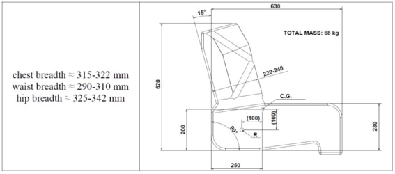
- If the simulated occupant loads result in the omnibus being loaded to less than its ‘GVM’, additional ballast is added to the omnibus in the following manner until the omnibus is loaded to its ‘GVM’ without exceeding any ‘GALR’: First, 7kg of ballast for each passenger is secured above each passenger where there is a luggage compartment else under the seat of each passenger; second, ballast is added to the lowest baggage compartment under the vehicle.
- If the simulated occupant loads result in the ‘GALR’ of any ‘Axle’ being exceeded or the ‘GVM’ of the omnibus being exceeded, simulated occupant loads shall be removed until the ‘GVM’ and each ‘GALR’ are no longer exceeded.
- Mass estimation cycle
- A mass estimation procedure for the ‘Vehicle Stability Function’ may be performed in accordance with the vehicle ‘Manufacturer’s’ instructions. This procedure may be repeated if an ignition cycle occurs or is needed at any time between the initiation and completion of the J-Turn test procedures prescribed in clause 6 of this annex.
- Tyre conditioning
- The tyres must be conditioned to wear away mould sheen and achieve operating temperature immediately before beginning the J-Turn tests. The test vehicle shall be driven around a circle 45 ± 10 metres in radius at a speed that produces a ‘Lateral Acceleration’ of approximately 0.1g for two clockwise laps followed by two anti-clockwise laps.
- Brake burnishing
- The brakes may be burnished using any number of brake applications recommended by the vehicle ‘Manufacturer’. The brakes may be adjusted up to three times during the burnishing procedure, at intervals specified by the vehicle ‘Manufacturer’, and may be adjusted at the conclusion of the burnishing, in accordance with the vehicle ‘Manufacturer’s’ recommendation.
- Brake temperature conditioning and monitoring
- The individual brake temperatures must be between 66 °C and 204 °C for each J-Turn test prescribed in clause 6 of this annex.
- The brakes shall be warmed up to temperatures within the required 66 °C to 204 °C range by subjecting the vehicle to a number of sequential brake applications.
- If the temperature of any brake exceeds 204 °C during J-Turn testing, a cool down period shall be observed until the temperature of each individual brake is within the required 66 °C to 204 °C range.
- If the temperature of any individual brake falls below 66 °C during J-Turn testing, a series of sequential brake applications shall be conducted until the temperature of each individual brake is within the required 66 °C to 204 °C range.
- Except as provided in clause 5.5.1 below, individual brake temperatures must be measured by a plug-type thermocouple installed at approximately 1.0 mm depth in the approximate centre of the facing length and width of the most heavily loaded shoe or disc pad of each brake. A second thermocouple may be installed at the beginning of the test sequence if the lining wear is expected to reach a point causing the first thermocouple to contact the rubbing surface of a drum or rotor. This second thermocouple should be installed at a depth of approximately 2.0 mm and located within 25.4 mm circumferentially of the thermocouple installed at 1.0 mm depth. For centre‑grooved shoes or pads, the thermocouples should be installed within 3.2 mm to 6.4 mm of the groove and as close to the centre of the facing length as possible.
- A different method may be used to measure the individual brake temperatures, if it can be shown to be sufficiently accurate, for the purposes of this annex, in determining the temperature at the approximate centre of the facing length and width of the most heavily loaded shoe or disc pad of each brake.
- J-Turn test procedures
The vehicle must be subjected to multiple series of tests using the ‘J‑Turn Test Course’. The vehicle travels through the course by driving down the entrance lane, crossing the start gate at the designated entrance speed, turning through the curved lane section, and crossing the end gate, while the driver attempts to keep all of the wheels of the vehicle within the lane.
- Reference Speed tests
The vehicle must be subjected to a series of J-Turn tests to determine the Reference Speed for each steering direction. The Reference Speed is used in the Engine Torque Reduction Tests, and the Directional Control and Roll‑over Control Tests.
- Preliminary Reference Speed determination
- The vehicle must be subjected to two series of tests using the ‘J-Turn Test Course’ at increasing ‘Entrance Speeds’. One series must be conducted using clockwise steering, and the other series anti‑clockwise steering.
- During each test, the driver attempts to maintain the selected ‘Entrance Speed’ throughout the ‘J-Turn Test Course’.
- The required ‘Entrance Speed’ (± 2 km/h) for the first test of each series may be determined by the ‘Manufacturer’, using the expression:
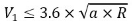
where:
V1 = the ‘Entrance Speed’ (in km/h) for the first test in a series;
a = the minimum ‘Lateral Acceleration’ (in m/s2) at which the ‘Manufacturer’ anticipates, ‘Vehicle Stability Function Service Brake Application’ may occur (not to exceed 3.89 m/s2); and
R = the fixed radius (in metres) of the ‘J-Turn Test Course’ (measured from the centre of the lane) selected by the ‘Manufacturer’.
Otherwise (i.e. where not determined as per the above expression by the ‘Manufacturer’), the ‘Entrance Speed’ for the first test in each series must be 32 km/h ± 2 km/h.
- The ‘Entrance Speed’ shall be incrementally increased by up to 2 km/h for each subsequent test until ‘Vehicle Stability Function Service Brake Application’ occurs or any of the wheels of the power driven vehicle depart the lane. The ‘Entrance Speed’ at which ‘Vehicle Stability Function Service Brake Application’ occurs is the Preliminary Reference Speed.
- The Preliminary Reference Speed must be determined for each direction: Clockwise steering and anti-clockwise steering. During any test, if any of the wheels of the power driven vehicle depart the lane at any point within the first 120 degrees of radius arc angle, the test shall be repeated at the same ‘Entrance Speed’. If any of the wheels of the power driven vehicle depart the lane again, then four consecutive tests shall be repeated at the same ‘Entrance Speed’ less 1 km/h.
- Reference Speed determination
- Two series of tests must be performed using the ‘J-Turn Test Course’, at the Preliminary Reference Speed (±2 km/h) determined in clause 6.1.1 above, to determine the Reference Speed. One series shall consist of up to four consecutive tests performed using anti-clockwise steering. The other series shall consist of up to four consecutive tests performed using clockwise steering.
- During each test, the driver attempts to maintain a speed equal to the Preliminary Reference Speed throughout the ‘J-Turn Test Course’. The Reference Speed is the minimum ‘Entrance Speed’ at which ‘Vehicle Stability Function Service Brake Application’ occurs for at least two of not more than four consecutive tests within each series conducted at the same ‘Entrance Speed’ (within ±2 km/h).
- The Reference Speed must be determined for each direction: clockwise steering and anti-clockwise steering. If ‘Vehicle Stability Function Service Brake Application’ does not occur during at least two tests within either series, the Preliminary Reference Speed shall be increased by up to 2 km/h, and the procedure in this section repeated.
- Engine torque reduction tests
- Two series of tests must be performed using the ‘J-Turn Test Course’, at the Reference Speed (±2 km/h) determined in clause 6.1.2 above. One series shall consist of up to four consecutive tests performed using anti‑clockwise steering. The other series shall consist of up to four consecutive tests performed using clockwise steering.
- During each test, the driver must fully depress the accelerator pedal from the time when the vehicle crosses the start gate until the vehicle reaches the end gate.
- Directional Control and Roll-over Control tests
- Two series of tests must be performed as follows using the ‘J-Turn Test Course’. One series shall consist of up to eight consecutive tests performed using anti‑clockwise steering. The other series shall consist of up to eight consecutive tests performed using clockwise steering. The ‘Entrance Speed’ for each test in each of these test series (clockwise steering and anticlockwise steering) must be at least, the greater of:
- 1.25 × the Reference Speed (see clause 6.1.2 above); and
- VRmax.
where:

R = the fixed radius (in metres) of the ‘J-Turn Test Course’ (measured from the centre of the lane) selected by the ‘Manufacturer’.
- The brake temperatures shall be monitored and the ‘Initial Brake Temperature’ confirmed to be between 66 °C and 204 °C. If the ‘Initial Brake Temperature’ is not between 66 °C and 204 °C, the brake temperatures shall be adjusted in accordance with clause 5 of this annex.
- During each test, the driver must not release the accelerator pedal until after the ‘Vehicle Stability Function Service Brake Application’ has slowed the vehicle by more than 4.8 km/h below the ‘Entrance Speed’.
- ‘Vehicle Stability Function’ failure/defect test procedures
- Simulate one or more ‘Vehicle Stability Function’ failure(s) or defect(s) by disconnecting the power source to any ‘Vehicle Stability Function’ component, or disconnecting any electrical connection between ‘Vehicle Stability Function’ components (with the vehicle power off). When simulating a ‘Vehicle Stability Function’ failure or defect, the electrical connections for the tell-tale lamp(s) are not disconnected.
- With the vehicle initially stationary and the ignition locking system in the “Lock” or “Off” position, activate the ignition locking system to the “Start” position and start the engine. Place the vehicle in a forward gear and accelerate to 48 ± 8 km/h. Drive the vehicle for at least two minutes including at least one left and one right turning manoeuvre and at least one service brake application. Verify that, within two minutes of attaining this speed, the ‘Vehicle Stability Function’ failure/defect indicator illuminates in accordance with clause 3.3 of APPENDIX 3 of this standard.
- Stop the vehicle, deactivate the ignition locking system to the “Off” or “Lock” position. After a five-minute period, activate the vehicle’s ignition locking system to the “Start” position and start the engine. Verify that the ‘Vehicle Stability Function’ failure/defect indicator again illuminates to signal a failure/defect and remains illuminated as long as the engine is running until the fault is corrected.
- Deactivate the ignition locking system to the “Off” or “Lock” position. Restore the ‘Vehicle Stability Function’ to normal operation, activate the ignition system to the “Start” position and start the engine. Verify that the tell-tale has extinguished.
- Data processing
- Raw vehicle speed data must be filtered with a 0.1 second running average filter.
- The torque data collected from the vehicle communication network or CAN bus as a digital signal must not be filtered.
- The torque data collected from the vehicle communication network or CAN bus as an analogue signal must be filtered with a 0.1-second running average.
- The time measurement for the J-Turn test procedure must be referenced to ‘Time Zero’.
- Raw service brake pressure measurements must be zeroed (calibrated). Zeroed brake pressure data must be filtered with 0.1 second running average filters. Zeroed and filtered brake pressure data must be dynamically offset corrected using a ‘Zeroing Range’.
TABLE 7
SUMMARY OF VEHICLE STABILITY FUNCTION TESTS
Tests and Procedures | Vehicle Category | Initial Speed (km/h) | Vehicle Mass | Transmission Condition(s) |
Preliminary Reference Speed Determination | ME (> 12 tonnes ‘GVM’ only)* NC (‘Prime Movers’ only)** | See text (clause 6.1.1) | M | D |
Reference Speed Determination | ME (> 12 tonnes ‘GVM’ only)* NC (‘Prime Movers’ only)** | See text (clause 6.1.2) |
Engine Torque Reduction Tests | ME (> 12 tonnes ‘GVM’ only)* NC (‘Prime Movers’ only)** | Reference Speed ± 2 |
Directional and Roll‑over Control Laden Effectiveness Tests | ME (> 12 tonnes ‘GVM’ only)* NC (‘Prime Movers’ only)** | ≥ 1.25 × Reference Speed |
* excluding any ‘Articulated Omnibus’, any ‘Route Service Omnibus’, and any vehicle designed for off-road use (refer APPENDIX 1 for definition)
** excluding any ‘Prime Mover’ with four or more axles, and any vehicle designed for off-road use (refer APPENDIX 1 for definition)
“M” means ‘Maximum Loaded Test Mass 35/...’
“D” means transmission control in “drive” position appropriate to test speed and engine/motor connected
APPENDIX 3 – Annex 2
‘Vehicle Stability Function’ simulation for category ME vehicles with a ‘GVM’ exceeding 12 tonnes and category NC ‘Prime Movers’
- Use of the dynamic stability simulation
- A dynamic stability simulation may only be used when each relevant parameter of the vehicle to be type approved (certified), as listed in clause 2.1 of this annex below, is included in the simulation tool and when the value of each parameter falls within its respective validated range. The verification must be carried out using each of the manoeuvre(s) specified in clause 6 of Annex 1 to this appendix.
- Specification of the dynamic stability simulation
- The simulation must take into account the main factors that influence the directional and roll motion of the vehicle.
- The simulation tool (i.e. simulator) and/or the simulation model used for a particular vehicle type must take into account the following vehicle parameters as applicable:
- Vehicle category;
- Gearbox type (e.g. manual, automated manual, semi-automatic, automatic);
- Differential type (e.g. standard or self-locking);
- Differential lock(s) (driver selected);
- ‘Brake System’ type (e.g. air over hydraulic, full air);
- Brake type (e.g. disc, drum (single wedge, twin wedge, S-cam));
- Tyre type (e.g. structure, category of use, size); and
- Suspension type (e.g. air, mechanical, rubber, hydraulic).
- Vehicle configuration(s) (e.g. 4x2, 6x2, 6x4 etc., identifying axle functionality (e.g. free running, driven, lifted, steered) and position);
- Steering ‘Axle(s)’ (working principle);
- Steering ratio;
- Drive ‘Axle(s)’ (effect on wheel speed sensing and vehicle speed);
- Lift ‘Axle(s)’ (detection/control and wheelbase change effect when lifted);
- Engine management (communication, control and response);
- Gearbox characteristic(s);
- Drive train option(s) (e.g. retarder, regenerative braking, auxiliary propulsion system);
- Brake characteristic(s);
- ‘Antilock System’ configuration;
- ‘Wheelbase’;
- Track width;
- Centre of gravity height;
- Lateral acceleration sensor position;
- Yaw rate sensor position; and
- Loading.
- The ‘Vehicle Stability Function’ must be added to the simulation model by means of:
- A subsystem (software model) of the simulation model; or
- The electronic control box in a hardware-in-the-loop configuration.
- Validation of the dynamic stability simulation
- The validity of the applied simulation and modelling must be verified by means of comparisons with practical vehicle tests. The tests utilised for the validation must be the J-Turn test procedures of clause 6 of Annex 1 to this appendix. The objective is to show that the simulated vehicle behaviour and operation of the ‘Vehicle Stability Function’ is comparable with that seen in practical vehicle tests.
- During the vehicle tests utilised for validation, the following motion variables, as appropriate, shall be recorded or calculated in accordance with ISO 15037 Part 2:2002 – General conditions for heavy vehicles and buses:
- Steering-wheel angle (H);
- Longitudinal velocity (vX);
- Lateral acceleration (aY);
- Yaw velocity (d/dt);
- Roll velocity (d/dt);
- Pitch velocity (d/dt);
- Roll angle (); and
- Pitch angle ().
- A simulator will be deemed to be validated, if its output is comparable to the practical test results produced by a given vehicle type during each of the dynamic manoeuvres specified in clause 6 of Annex 1 to this appendix.
- The simulation tool may only be used with regard to features for which a comparison has been made between real vehicle tests and simulation tool results.
- Comparisons must be carried-out in the fully laden condition for at least one variant of the vehicle type certified/approved with each of the following:
- the shortest ‘Wheelbase’;
- the longest ‘Wheelbase’; and
- the highest centre of gravity.
- In the case of a dynamic J-Turn manoeuvre, the relationship of activation and sequence of the ‘Vehicle Stability Function’ in the simulation and in the practical vehicle test shall be the means of making the comparison.
- The physical parameters that are different between the reference vehicle and simulated vehicle configurations must be modified accordingly in the simulation.
- The suitability of the simulation tool for use with any other parameters not validated by a practical vehicle test may be demonstrated by conducting simulations with varied parameter values. The results of these simulations shall be checked to be logical and similar in comparison to the results of known practical vehicle tests.
APPENDIX 3 – Annex 3
‘Vehicle Stability Function’ simulation test report
- Test Facility No:
- Test Report Number:
- Identification
- Name and address of the simulation tool manufacturer:
- Simulation tool identification: name/model/number (hardware and software)
- Simulation tool
- Simulation method (general description, taking into account the requirements of clause 2.1 of Annex 2 to this appendix):
- Hardware/software in the loop (see clause 2.2 of Annex 2 to this appendix):
- Validation (see clause 3 of Annex 2 to this appendix):
- Motion variables (see clause 3.2 of Annex 2 to this appendix):
- Scope of application
- Vehicle category:
- Vehicle configuration(s):
- Steering ‘Axle(s)’:
- Steering ratio:
- Drive ‘Axle(s)’:
- Lift ‘Axle(s)’:
- Engine management:
- Gearbox type:
- Drive train options:
- Differential type:
- Differential lock(s):
- ‘Brake System’ type:
- Brake type:
- Brake characteristics:
- ‘Antilock System’ configuration:
- ‘Wheelbase’:
- Tyre type:
- Track width:
- Suspension type:
- Centre of gravity height:
- Lateral acceleration sensor position:
- Yaw rate sensor position:
- Loading:
- J-Turn manoeuvre(s) for which the simulation tool has been validated:
- Any limiting factors:
- Verifying vehicle test
- Description of vehicle(s):
- Vehicle(s) identification: make/model/VIN
- Vehicle description, including suspension/wheels, engine and drive line, braking system(s), steering system, with name/model/number identification:
- Vehicle data used in the simulation (explicit):
- Description of location(s), road/test area surface conditions, temperature and date(s):
- Laden test results with the ‘Vehicle Stability Function’ on, including the motion variables referred to in clause 3.2 of Annex 2 to this appendix, as appropriate:
- Simulation results
- Vehicle parameters and the values used in the simulation that are not taken from the actual test vehicle (implicit):
- Laden simulation results with the ‘Vehicle Stability Function’ on, including the motion variables referred to in clause 3.2 of Annex 2 to this appendix, as appropriate:
- Concluding statements
- The simulated vehicle behaviour and operation of the ‘Vehicle Stability Function’ is comparable with that of practical vehicle tests: Yes/No
- This simulation tool test has been carried out and the results reported in accordance with APPENDIX 3 – Annex 2 to the Australian Design Rule 35/06: Yes/No.
- Signed:
- Dated:
APPENDIX 4
Electrical requirements for all vehicles equipped to tow a trailer with an ‘ATM’ greater than 4.5 tonnes
- Electrical supply system requirements
- The vehicle must have a permanent electrical supply system for connection to trailers using a special connector conforming to ISO 7638‑1:2003 configured for 24 volt operation or ISO 7638‑2:2003 configured for 12 volt operation. The power supply must provide DC current having a nominal voltage level of 12 volts or 24 volts.
- Each ISO 7638 connector must be wired to have the following functions:
Contact 1 +ve high current trailer solenoid valve supply;
Contact 2 +ve low current trailer electronic unit supply;
Contact 3 -ve low current trailer electronic unit supply;
Contact 4 -ve high current trailer solenoid valve supply; and
Contact 5 trailer warning signal, switched to -ve (e.g. contact 3 or contact 4) upon fault detection.
- Either the optical warning lamp specified in clause 1.2 of APPENDIX 2 or an additional yellow optical warning signal (appropriately labelled) must light up whenever contact 5 of an ISO 7638 connector is connected to ground or a -ve connector.
- The power supply provided by an ISO 7638 connector must be used exclusively for braking and running gear functions and that required for the transfer of trailer related information not transmitted via an electric ‘Control Line’.
- However, in all cases, whenever power supplied by an ISO 7638 connector is used for the functions defined in this clause above, the braking system must have priority and be protected from an overload external to the braking system. This protection must be a function of the braking system. The power supply for all other functions must use other measures.
- Electric ‘Control Line’ requirements
- Where the vehicle also provides an electric ‘Control Signal’ via an electric ‘Control Line’:
- The communications via the electric ‘Control Line’ must conform to ISO 11992‑1:2003 and ISO 11992‑2:2003 including its amendment 1:2007.
- The electric ‘Control Line’ must be a point-to-point type using a seven contact connector in accordance with ISO 7638‑1:2003 or ISO 7638‑2:2003; as per which, contact 6 must be wired for the CAN_H signal and contact 7 must be wired for the CAN_L signal.
- The electric ‘Control Line’ must meet the requirements of ISO 11992‑1:2003, including:
- The wiring must be an unshielded twisted pair; and
- The maximum cable length of the electric ‘Control Line’ within the vehicle must not exceed 15 m and the bus capacitance of the cable must not exceed 750 pF.
- The data contacts of an ISO 7638 connector incorporating an electric ‘Control Line’ must be used to transfer information exclusively for braking (including the ‘Vehicle Stability Function’ and ‘Antilock System’) and running gear (steering, tyres and suspension) functions as specified in ISO 11992‑2:2003.
- The braking functions have priority and must be maintained in the normal and failed modes. The transmission of running gear information must not delay braking functions.
- When a power-driven vehicle is equipped with an electric ‘Control Line’ and electrically connected to a trailer equipped with an electric ‘Control Line’, a continuous failure (> 40 ms) within the electric ‘Control Line’ must be detected in the power-driven vehicle and must be signalled to the driver by a yellow optical warning signal appropriately labelled and located in accordance with clause 5.2.12 of this standard, when such vehicles are connected via the electric ‘Control Line’.
APPENDIX 5
Additional requirements for certain vehicles equipped with an ‘Endurance Braking System’ and/or an ‘Electric Regenerative Braking System of Category A’
- Definitions
- ‘Electric Regenerative Braking System’ means a ‘Brake System’ which, during deceleration, provides for the conversion of vehicle kinetic energy into electrical energy.
- ‘Electric Regenerative Braking System of Category A’ means an ‘Electric Regenerative Braking System’ which is not part of the ‘Service Brake System’.
- ‘Endurance Braking System’ means an additional ‘Brake System’ having the capability to provide and to maintain a braking effect over a long period of time without a significant reduction in performance.
- The term ‘Endurance Braking System’ covers the complete system including the ‘Control’ device.
- The ‘Endurance Braking System’ may comprise a single device or a combination of several devices. Each device may have its own ‘Control’.
- Requirements
- Each vehicle equipped with an ‘Endurance Braking System’ and/or an ‘Electric Regenerative Braking System of Category A’ must generate the signal necessary to illuminate the stop lamps, when the retardation generated by the ‘Endurance Braking System’ and/or ‘Electric Regenerative Braking System’ exceeds 1.3 m/s2.
ENDNOTES
Endnote 1—About the endnotes
The endnotes provide information about this compilation and the compiled law.
The following endnotes are included in every compilation:
Endnote 1—About the endnotes
Endnote 2—Abbreviation key
Endnote 3—Legislation history
Endnote 4—Amendment history
Abbreviation key—Endnote 2
The abbreviation key sets out abbreviations that may be used in the endnotes.
Legislation history and amendment history—Endnotes 3 and 4
Amending laws are annotated in the legislation history and amendment history.
The legislation history in endnote 3 provides information about each law that has amended (or will amend) the compiled law. The information includes commencement details for amending laws and details of any application, saving or transitional provisions that are not included in this compilation.
The amendment history in endnote 4 provides information about amendments at the provision (generally section or equivalent) level. It also includes information about any provision of the compiled law that has been repealed in accordance with a provision of the law.
Misdescribed amendments
A misdescribed amendment is an amendment that does not accurately describe how an amendment is to be made. If, despite the misdescription, the amendment can be given effect as intended, then the misdescribed amendment can be incorporated through an editorial change made under section 15V of the Legislation Act 2003.
If a misdescribed amendment cannot be given effect as intended, the amendment is not incorporated and “(md not incorp)” is added to the amendment history.
Endnote 2—Abbreviation key
ad = added or inserted | orig = original |
am = amended | par = paragraph(s)/subparagraph(s) |
amdt = amendment | /sub‑subparagraph(s) |
c = clause(s) | pres = present |
C[x] = Compilation No. x | prev = previous |
Ch = Chapter(s) | (prev…) = previously |
def = definition(s) | Pt = Part(s) |
Dict = Dictionary | r = regulation(s)/rule(s) |
disallowed = disallowed by Parliament | reloc = relocated |
Div = Division(s) | renum = renumbered |
exp = expires/expired or ceases/ceased to have | rep = repealed |
effect | rs = repealed and substituted |
F = Federal Register of Legislation | s = section(s)/subsection(s) |
gaz = gazette | Sch = Schedule(s) |
LA = Legislation Act 2003 | Sdiv = Subdivision(s) |
LIA = Legislative Instruments Act 2003 | SLI = Select Legislative Instrument |
(md not incorp) = misdescribed amendment | SR = Statutory Rules |
cannot be given effect | Sub‑Ch = Sub‑Chapter(s) |
mod = modified/modification | SubPt = Subpart(s) |
No. = Number(s) | underlining = whole or part not |
o = order(s) | commenced or to be commenced |
Ord = Ordinance | |
Endnote 3—Legislation history
Name | Registration | Commencement | Application, saving and transitional provisions |
Vehicle Standard (Australian Design Rule 35/06 – Commercial Vehicle Brake Systems) 2018 | 29/05/2018 | 30/05/2018 | |
Vehicle Standard (Australian Design Rule 35/06 – Commercial Vehicle Brake Systems) 2018 Amendment 1 | 01/03/2022 | 02/03/2022 | |
Vehicle Standard (Australian Design Rule) Safer Freight Vehicles Amendment No. 1 2023 | 28/09/2023 | 29/09/2023 | |
Endnote 4—Amendment history
Provision affected | How affected | Amending legislation/instrument |
c 1.3 | rep | LA s 48D |
c 3.1 | am | Vehicle Standard (Australian Design Rule 35/06 – Commercial Vehicle Brake Systems) 2018 Amendment 1 |
c 3.10 | renum 3.11 | Vehicle Standard (Australian Design Rule 35/06 – Commercial Vehicle Brake Systems) 2018 Amendment 1 |
c 3.10 | ad | Vehicle Standard (Australian Design Rule 35/06 – Commercial Vehicle Brake Systems) 2018 Amendment 1 |
c9.2 | am | Vehicle Standard (Australian Design Rule) Safer Freight Vehicles Amendment No. 1 2023 |
c9.2.5 | ad | Vehicle Standard (Australian Design Rule) Safer Freight Vehicles Amendment No. 1 2023 |
Appendix c2.1(a) | am | Vehicle Standard (Australian Design Rule) Safer Freight Vehicles Amendment No. 1 2023 |