- LEGISLATIVE PROVISIONS
- Name of Standard
- This Standard is the Vehicle Standard (Australian Design Rule 42/05 – General Safety Requirements) 2018.
- This Standard may also be cited as Australian Design Rule 42/05 – General Safety Requirements.
- Commencement
- This Standard commences on the day after it is registered.
- FUNCTION
- The function of this vehicle standard is to specify general design and construction requirements to ensure safe operation of vehicles.
- APPLICABILITY
- This vehicle standard applies to all categories of vehicles from the dates set out in clauses 3.1.1 to 3.1.2 and the applicability table under clause 3.8 below.
- 1 July 2019 for all new model vehicles.
- There is no mandatory application date for all other vehicles. They may comply with this vehicle standard, or continue to comply with the Australian Design Rule 42/04 – General Safety Requirements.
- For the purposes of clause 3.1.1, a “new model” is a vehicle model first produced with a ‘Date of manufacture’ on or after the agreed date in that clause.
- Category LA, LB, LC, LD, and LE vehicles (L‑Group vehicles) certified to this standard must also be certified to each of the applicable Australian Design Rules specified in Table 1 under clause 3.9 below.
- Category MA, MB, MC, MD and ME vehicles (M‑Group vehicles) certified to this standard must also be certified to each of the applicable Australian Design Rules specified in Table 2 under clause 3.9 below.
- Category NA, NB and NC vehicles (N‑Group vehicles) certified to this standard must also be certified to each of the applicable Australian Design Rules specified in Table 3 under clause 3.9 below.
- Category TA, TB, TC and TD vehicles (T‑Group vehicles) certified to this standard must also be certified to each of the applicable Australian Design Rules specified in Table 4 under clause 3.9 below.
- Where the requirements of a particular clause of this standard do not apply to all vehicles, the relevant categories are identified in the clause or clause heading.
3.8. Applicability Table
Vehicle Category | ADR Category Code | UN Category Code | Manufactured on or After[**] | Acceptable Prior Rules |
Moped 2 wheels | LA | L1 | 1 July 2019 | See clause 3.1.2. |
Moped 3 wheels | LB | L2 | 1 July 2019 | See clause 3.1.2. |
Motorcycle | LC | L3 | 1 July 2019 | See clause 3.1.2. |
Motorcycle and sidecar | LD | L4 | 1 July 2019 | See clause 3.1.2. |
Motor tricycle | LE | L5 | | |
| LEM | | 1 July 2019 | See clause 3.1.2. |
| LEP | | 1 July 2019 | See clause 3.1.2. |
| LEG | | 1 July 2019 | See clause 3.1.2. |
Passenger car | MA | M1 | 1 July 2019 | See clause 3.1.2. |
Forward-control passenger vehicle | MB | M1 | 1 July 2019 | See clause 3.1.2. |
Off-road passenger vehicle | MC | M1 | 1 July 2019 | See clause 3.1.2. |
Light omnibus | MD | M2 | | |
| up to 3.5 tonnes ‘GVM’ and up to 12 seats | MD1 | | 1 July 2019 | See clause 3.1.2. |
| up to 3.5 tonnes ‘GVM’ and more than 12 seats | MD2 | | 1 July 2019 | See clause 3.1.2. |
| over 3.5 tonnes and up to 4.5 tonnes ‘GVM’ | MD3 | | 1 July 2019 | See clause 3.1.2. |
| over 4.5 tonnes and up to 5 tonnes ‘GVM’ | MD4 | | 1 July 2019 | See clause 3.1.2. |
Heavy omnibus | ME | M3 | 1 July 2019 | See clause 3.1.2. |
Light goods vehicle | NA | N1 | 1 July 2019 | See clause 3.1.2. |
Medium goods vehicle | NB | N2 | | |
| over 3.5 tonnes up to 4.5 tonnes ‘GVM’ | NB1 | | 1 July 2019 | See clause 3.1.2. |
| over 4.5 tonnes up to 12 tonnes ‘GVM’ | NB2 | | 1 July 2019 | See clause 3.1.2. |
Heavy goods vehicle | NC | N3 | 1 July 2019 | See clause 3.1.2. |
Very light trailer | TA | O1 | 1 July 2019 | See clause 3.1.2. |
Light trailer | TB | O2 | 1 July 2019 | See clause 3.1.2. |
Medium trailer | TC | O3 | 1 July 2019 | See clause 3.1.2. |
Heavy trailer | TD | O4 | 1 July 2019 | See clause 3.1.2. |
3.9. Other applicable Australian Design Rules (ADRs)
Table 1: L-Group Vehicles (Two-Wheeled and Three-Wheeled Vehicles) |
Vehicles certified to this standard must also be certified to: | ADR Category Code (UN Category Code) |
LA (L1) | LB (L2) | LC (L3) | LD (L4) | LEM (L5) | LEP (L5) | LEG (L5) |
ADR 90/… – Steering System | n/a | X | n/a | X | X | X | X |
ADR 92/… – External Projections | X | X | X | X | X | X | X |
ADR 93/… – Forward Field of View | X | X | X | X | X | X | X |
ADR 94/… – Audible Warning | X | X | X | X | X | X | X |
ADR 95/… – Installation of Tyres | X | X | X | X | X | X | X |
Table 2: M-Group Vehicles (Passenger Vehicles including Omnibuses) |
Vehicles certified to this standard must also be certified to: | ADR Category Code (UN Category Code) |
MA (M1) | MB (M1) | MC (M1) | MD1 (M2) | MD2 (M2) | MD3 (M2) | MD4 (M2) | ME (M3) |
ADR 90/… – Steering System | X | X | X | X | X | X | X | X |
ADR 92/… – External Projections | X | X | X | X | X | X | X | X |
ADR 93/… – Forward Field of View | X | X | X | X | X | X | X | X |
ADR 94/… – Audible Warning | X | X | X | X | X | X | X | X |
ADR 95/… – Installation of Tyres | X | X | X | X | X | X | X | X |
Table 3: N-Group Vehicles (Goods Vehicles) |
Vehicles certified to this standard must also be certified to: | ADR Category Code (UN Category Code) |
NA (N1) | NB1 (N2) | NB2 (N2) | NC (N3) |
ADR 90/… – Steering System | X | X | X | X |
ADR 92/… – External Projections | X | X | X | X |
ADR 93/… – Forward Field of View | X | X | X | X |
ADR 94/… – Audible Warning | X | X | X | X |
ADR 95/… – Installation of Tyres | X | X | X | X |
Table 4: T-Group Vehicles (Trailers) |
Vehicles certified to this standard must also be certified to: | ADR Category Code (UN Category Code) |
TA (O1) | TB (O2) | TC (O3) | TD (O4) |
ADR 91/… – Rear Underrun Impact Protection | n/a | n/a | XS | XS |
ADR 92/… – External Projections | X | X | X | X |
ADR 95/… – Installation of Tyres | X | X | X | X |
X means applicable
XS means applicable for ‘Semi-trailers’ only
n/a means not applicable
4. DEFINITIONS
4.1. For vehicle categories, definitions and meanings used in this standard, refer to:
4.1.1. Vehicle Standard (Australian Design Rule Definitions and Vehicle Categories) 2005; and
4.1.2. Definitions in clause 1 of APPENDIX 1 of this standard.
5. Steering CONTROL
5.1. The centreline of the steering control must not be located to the left of the centreline of the vehicle.
6. Controls for Diesel and/OR Automatic Vehicles
6.1. In the case of a vehicle with a diesel engine, a locking device must be fitted which prevents the engine from being started by any accidental or inadvertent means.
6.2. In the case of an M-Group or N-Group vehicle with an automatic transmission, actuation of the ‘Engine start control’ must not cause the vehicle to move.
7. Bonnet latching
7.1. Any movable body panel forward of the windscreen that serves to cover an engine, luggage, storage or battery compartment must be provided with a latch system.
7.2. A panel opening from the front, which in any open position, partially or completely obstructs a driver’s forward view through the windscreen, must be provided with a second latch position on the latch system, or with a second latch system.
8. Windscreen wipers and washers
8.1. Category LEM, LEP and LEG vehicles
8.1.1. Every enclosed category LEM vehicle with a windscreen and every category LEP or LEG vehicle with a windscreen must be fitted with a power-driven windscreen wiping system.
8.1.2. Every vehicle with a windscreen wiping system must have a windscreen washing system that can direct water onto the windscreen within the area swept by the windscreen wiper.
8.1.2.1. The device or devices for operating the wipers and washer must be able to be controlled by the driver in the normal driving position.
8.2. M-Group and N-Group vehicles
8.2.1. Every vehicle with a windscreen must be fitted with a power-driven windscreen wiping system and must have a windscreen washing system that can direct water onto the windscreen within the area swept by the windscreen wiper.
8.2.1.1. The device or devices for operating the wipers and washer must be able to be controlled by the driver in the normal driving position.
9. Demisting of windscreens
9.1. Category LEP and LEG vehicles, and M-Group and N-Group vehicles
9.1.1. Every vehicle with a windscreen, and a roof or provision for a roof, must be fitted with a device capable of removing condensed moisture from the inside of the windscreen.
10. Brake Hose and brake Tubing
10.1. Flexible hydraulic brake hoses, air and vacuum brake tubing, air and vacuum hose, and flexible and hydraulic power hose, between the ‘Brake Power Unit 31/00’ or ‘Brake Power Unit 35/...’ and the master cylinder or its equivalent must:
(a) conform to any edition of the United States Federal Motor Vehicle Safety Standard (FMVSS) No. 106 (49.CFR.571.106 – Brake Hoses) in force between 1 October 2010 and the commencement of this rule, or to an applicable SA, SAE, BS, JIS, DIN, ISO or UN standard for flexible brake hoses, air brake tubing or hose, vacuum brake tubing or hose, or hydraulic power tubing or hose, current between 1 January 2005 and the commencement of this rule; and
(b) be fitted/routed so as to prevent chafing, kinking or other mechanical damage under normal motion of the moving vehicle parts.
11. Provision of Reverse gear
11.1. Category LEM, LEP and LEG vehicles
11.1.1. All vehicles, except for non-enclosed vehicles with an ‘Unladen Mass’ less than 450 kg, must be capable of being operated by the driver from the normal seating position so that they may be propelled both forwards and backwards.
11.2. M-Group and N-Group vehicles
11.2.1. All vehicles must be capable of being operated by the driver from the normal seating position so that they may be propelled both forwards and backwards.
12. Internal protrusions
12.1. Vehicles must not be equipped with any interior object or fitting which, because it is pointed or has a sharp edge, is likely to increase the risk of bodily injury to any person.
13. Television and visual display units
13.1. Any television receiver(s), visual display unit(s) and associated equipment thereof, must be securely mounted in a position which:
(a) does not obscure the driver’s vision;
(b) does not impede driver or passenger movement in the vehicle; and
(c) is unlikely to increase the risk of occupant injury.
13.2. Unless a driver’s aid, any television receiver(s) or visual display unit(s) must be installed such that no part of the image on the screen is visible to the driver from the normal driving position.
14. Power Operated Window Systems
14.1. Category MA, MB and MC vehicles
14.1.1. Except as provided by clauses 14.1.3 and 14.1.4 below, the operation of ‘Power Operated Window’ systems must only be possible when:
(a) the key that controls activation of the vehicle’s engine is in an “ON”, “START” or “ACCESSORY” position; or
(b) the ignition switch has been actuated from “ON” to “OFF” position and/or the key has been removed and no front doors on the vehicle have been opened; or
(c) the key to lock the driver’s door is in the door lock; or
(d) upon activation by a key locking system on the exterior of the vehicle; or
(e) upon continuous operation of a remote actuation device, provided that the remote actuation device is incapable of opening/closing any ‘Power Operated Window’ from a distance of more than 11 metres from the vehicle; or
(f) when the ignition key has been removed, in which case the ‘Power Operated Window’ system may:
(i) remain operational for not more than 45 seconds; and
(ii) if the driver’s window is operated within the 45 second period, the windows can remain operational for an additional period of not more than 45 seconds, after activation of the driver’s window switch; and
(iii) if the driver’s door is opened within the 45 second period, the power operated window system can remain operational for an additional period of not more than 45 seconds, after the opening of the driver’s door.
14.1.2. Except as provided by clauses 14.1.3 and 14.1.4 below, only momentary type switches or valves shall be used for operating mechanisms to close any ‘Power Operated Windows’ of doors other than the driver’s door.
14.1.3. The requirements of clauses 14.1.1 and 14.1.2 above shall not apply whenever:
(a) the closing movement of a ‘Power Operated Window’ starts at an opening not exceeding 4 mm; or
(b) the closing of a ‘Power Operated Window’ of a vehicle’s door without upper door frame closes from an opening not exceeding 12 mm whenever the pertinent door is closed.
14.1.4. A ‘Power Operated Window’ system may also be capable of being closed under any circumstances other than those permitted by clauses 14.1.1 to 14.1.3 above, if:
(a) while closing, the window reverses direction before exerting a pinch force of 100 N or more within the range of 200 mm to 4 mm beneath the top edge of the power window frame; and
(b) upon such reversal, the window opens to at least one of the following positions:
(i) a position that is at least as open as the position at the time closing was initiated; or
(ii) a position at least 50 mm more open than the position at the time reversing was initiated; or
(iii) a position that permits a cylindrical rod 200 mm in diameter to be placed through the opening at the top edge of the window.
14.1.4.1. To check if a ‘Power Operated Window’ system automatically reverses according to parts (a) and (b) of this clause 14.1.4, a measuring instrument/test rod shall be placed through the window ‘Opening’ such that the cylindrical surface of the rod contacts the structure which forms the boundary of the window. The force/deflection ratio of the measuring instrument/test rod must be at least 10 N/mm. Figure 1 shows some example placements of the cylindrical test rods.
14.1.5. For the operation of rear window switches which are not situated in close proximity of the driver, the ‘Power Operated Window’ system must be designed to enable the driver to:
(a) turn off the switch(es) of the closing mechanism(s) of the rear window(s); and
(b) initiate opening of the rear window(s).
14.1.5.1. The requirement of part (b) of this clause 14.1.5 above need not be met if/when any rear window switch, which is situated out of the driver’s reach, is operated at the same time.
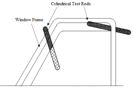
Figure 1: Typical cylindrical test rods protruding through window daylight openings
14.1.6. The technical requirements of the United States Federal Motor Vehicle Safety Standard (FMVSS) No. 118 (49.CFR.571.118 – Power-operated window, partition, and roof panel systems) – 10-1-17 edition, are deemed to be equivalent to the requirements of this clause 14.
15. Ventilation
15.1. At least half the number of windows must be openable or the vehicle must be provided with an alternative method of ventilation.
15.2. Omnibuses must be provided with a means of ventilation other than by means of windows and door openings.
15.2.1. Except in the case of omnibuses equipped with flow-through ventilation or refrigerated air-conditioning, the provision of an inlet air vent and at least two rotary vents or a hatch in the roof towards the rear of the passenger compartment, will be deemed to meet this clause 15.2.
16. SLEEPER BERTHS for Category NB OR NC vehicles
16.1. Every ‘Sleeper Berth’ must be located within the cab or immediately adjacent thereto and must be so constructed that any occupant will not be likely to be thrown out in the event of sudden deceleration of the vehicle.
16.2. A ‘Sleeper Berth’ must not be located within the cargo space unless such berth is completely and securely separated from the remainder of the cargo space.
16.3. Every ‘Sleeper Berth’ must be so constructed as to provide, at least the following internal dimensions:
(a) 1,900 mm long measured on the centreline of the longitudinal axis;
(b) 530 mm wide for 1,200 mm along the required length and 440 mm wide for the remainder of the required length; and
(c) 630 mm deep, of generally rectangular shape, except that the horizontal corners and the roof corner may be rounded to radii not exceeding 270 mm.
16.4. Except as provided by clause 16.4.1 below, every ‘Sleeper Berth’ must provide the occupant, without the assistance of other persons, with at least two exits at opposite sides of the vehicle, each being at least 450 mm high and 530 mm wide.
16.4.1. Two exits at opposite sides of the vehicle need not be provided where the ‘Sleeper Berth’ space is part of the vehicle cab and has a doorway or opening at least 450 mm in one direction and 910 mm in another direction between it and the driver seat.
16.5. Unless a ‘Sleeper Berth’ is located within the driver’s cab or is provided with a direct entrance thereto, a means must be provided to enable its occupant to communicate with the driver. Such means may include telephones, speaker tubes, buzzers, pull cords, or other mechanical or electrical means.
16.6. A ‘Sleeper Berth’ must not be so located as to:
(a) permit the ready entrance of gases from the exhaust system; or
(b) be overheated or damaged by reason of its proximity to the exhaust system.
16.7. A ‘Sleeper Berth’ must not be so located that defects in the ‘Fuel System 17/00’ would result in leakage on or into it.
16.8. Every ‘Sleeper Berth’ must be provided with proper ventilation and be tight against dust and rain.
17. ‘WHEEL GUARDS’ (‘MUDGUARDS’)
17.1. L-Group vehicles
17.1.1. The wheels of a vehicle, including any sidecar, must be fitted with ‘Wheel Guards’ of width not less than the ‘Section Width’ of the tyre.
17.1.2. The ‘Wheel Guards’ must be so designed as to protect other road users, as far as practicable, against thrown-up stones, mud, ice, snow and water and to reduce for those users the dangers due to contact with the moving wheels.
17.1.3. The ‘Wheel Guard(s)’ provided for the front ‘Axle’, must extend not less than from a point vertically above the centre of the wheel rearward to a point not higher than the centre of the wheel or to the point where suitable protection is afforded by the frame or other construction of the vehicle when a mass of 45 kg is distributed in the saddle of the vehicle at its ‘Unladen Mass’.
17.1.4. ‘Wheel Guards’ may consist of either permanent body structure or part structure and other components, including mudflaps, provided the specified protection is retained during vehicle operation.
17.2. Other than L-Group vehicles
17.2.1. All wheels of category MA vehicles must be provided with ‘Wheel Guards’ that comply with clause 17.2.4 below.
17.2.2. All wheels of category MB, MC, MD1, MD2, MD3, NA, NB1, TA and TB vehicles must be provided with ‘Wheel Guards’ that comply with clause 17.2.4 or clause 17.2.5 below.
17.2.3. All wheels of category MD4, ME, NB2, NC, TC and TD vehicles must be provided with ‘Wheel Guards’ that comply with clause 17.2.5 below.
17.2.4. ‘Wheel Guards’ for passenger cars and other light vehicles
17.2.4.1. The ‘Wheel Guards’ (parts of the bodywork, mudguards, etc.) must be so designed as to protect other road users, as far as practicable, against thrown-up stones, mud, ice, snow and water and to reduce for those users the dangers due to contact with the moving wheels.
17.2.4.2. When the wheels are in the straight ahead position:
(a) in the part formed by radial planes at an angle of 30 degrees to the front and 50 degrees to the rear of the centre of the wheel (see Figure 2), the overall width (q) of the ‘Wheel Guards’ must be at least sufficient to cover the ‘Section Width’ (b) of the tyres fitted to the vehicle, taking into account the extremes of tyre/wheel combination as specified by the ‘Manufacturer’;
(b) the rear of the ‘Wheel Guards’ must not terminate above a horizontal plane 150 mm above the axis of rotation of the wheels (as measured at the wheel centres) and furthermore the intersection of the edge of the ‘Wheel Guard’ with this plane (point A, Figure 2) must lie outside the median longitudinal plane of the tyre; and
(c) within the part formed by the radial planes referred to in part (a) above, the contour and location of the ‘Wheel Guards’ must satisfy the following requirements:
(i) the projection - situated in the vertical plane of the tyre axis - of the depth (p) of the outer edge of the ‘Wheel Guards’, measured in the vertical longitudinal plane passing through the centre of the tyre, must be at least 30 mm; and
(ii) the distance (c) between the lower edges of the ‘Wheel Guards’ and the axis passing through the centre of the wheels must not exceed 2r, ‘r’ being the ‘Static Loaded Tyre Radius’ of the tyre.
17.2.4.2.1. The depth (p) referred to in part (c)(i) of this clause 17.2.4.2 may be reduced progressively to zero at the radial planes specified in clause 17.2.4.2(a) above.
17.2.4.3. In the case of vehicles having adjustable suspension height, the above mentioned requirements must be met when the vehicle is in the normal running position specified by the ‘Manufacturer’.

Figure 2: ‘Wheel Guard’ coverage (passenger cars and other light vehicles)
17.2.5. ‘Wheel Guards’ for off-road and/or commercial vehicles
17.2.5.1. The ‘Wheel Guards’ must be so designed as to protect other road users, as far as practicable, against thrown-up stones, mud, ice, snow and water and to reduce for those users the dangers due to contact with the moving wheels.
17.2.5.2. The ‘Wheel Guards’ on the rearmost wheels must provide continuous protection between a point in area A and a point in area B in Figure 3, and must be provided for the ‘Overall Tyre Width’ (excluding the deflected part of the tyre sidewall, between the lowest point of the ‘Tyre Rim’ and the ground) of all tyres.
17.2.5.2.1. In the case of steerable wheels, the requirements of this clause 17.2.5.2 shall only apply when the wheels are in the straight-ahead position.
17.2.5.3. ‘Wheel Guards’ may consist of either permanent body structure or part structure and other components, including mudflaps, provided the specified protection is retained during vehicle operation.
17.2.5.4. Where two (2) or more ‘Axles’ form an ‘Axle Group’, separate ‘Wheel Guards’ may be provided for each rear wheel or a single ‘Wheel Guard’ may be provided which provides continuous protection from area ‘A’ of the foremost wheel to area ‘B’ of the rearmost wheel in Figure 3.
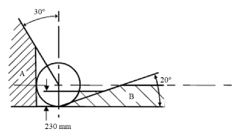
Figure 3: ‘Wheel Guard’ coverage (off-road and commercial vehicles)
17.2.5.5. Notwithstanding the requirements specified above, the ‘Wheel Guard’ including a mudflap (if fitted) need not be less than 230 mm from the ground for other than off-road vehicles, or 300 mm in the case of vehicles designed for off-road operation.
17.2.6. Visibility of ‘Wheel Guards’ (where applicable)
17.2.6.1. Except when ‘Rear Marking Plates’ are fitted, for every rear ‘Wheel Guard’ affixed to a motor vehicle, or trailer which is 2.2 metres or more in ‘Overall Width’ and which has a body of the tray type, that portion of the external surface of such ‘Wheel Guard’ which is visible to the rear of such vehicle must be white or silver in colour and clearly visible.
18. Retractable Axles
18.1. A ‘Control’ may be provided to manually move a ‘Retractable Axle’ up or down.
18.2. Where a manual ‘Control’ for lowering of a ‘Retractable Axle’ is fitted:
(a) the ‘Control’ or the enclosure in which it is contained must be lockable;
(b) the ‘Control’ must be located within 2.5 metres of the centreline of the ‘Axle Group’ which contains the ‘Retractable Axle’; and
(c) the ‘Control’ must not be accessible from within the cab of the vehicle.
18.3. Any ‘Retractable Axle’ must not be able to be moved from the ‘Fully-down’ position while the load on the ‘Axle Group’ is greater than the ‘Prescribed Transition Mass’.
18.4. Any system malfunction, attempted tampering or loss of power (e.g. trailer uncoupling) shall result in any ‘Retractable Axle’ moving to or staying in the ‘Fully-down’ position if the vehicle is loaded.
18.5. An audible warning device in accordance with clause 23.3 below must be fitted to each vehicle equipped with a ‘Retractable Axle’.
18.6. The vehicle must be marked on both sides within 2.0 metres of a transverse vertical plane through the centreline of the ‘Retractable Axle’ with “Warning: Axle(s) may raise or lower automatically”. This marking must be in letter height of 25 mm minimum with red coloured letters on a white background and in such a position as to be clearly visible to a person standing nearby.
19. RIM selection
19.1. L-Group vehicles
19.1.1. The sum of the load carrying capacities recommended for all ‘Rims’ with which the vehicle is equipped must not be less than the ‘GVM’.
19.2. Other than L-Group vehicles
19.2.1. All ‘Rims’ normally fitted to the vehicle must be suitable for the vehicle model/type, particularly with respect to their dimensions, speed and load performance characteristics.
19.2.2. For category MA vehicles (passenger cars), the rims fitted must comply with those listed for the tyre size designation in:
(a) ISO 4000-1:2015 (Passenger car tyres and rims Part 1: Tyres (metric series)); or
(b) the Tyre and Rim Association of Australia Standards Manual – 2018 edition; or
(c) the European Tyre and Rim Technical Organisation Standards Manual – 2018 edition; or
(d) the Japan Automobile Tyre Manufacturers Association, Inc. Year Book – 2018 edition; or
(e) the US Tyre and Rim Association, Inc. Year Book – 2018 edition.
20. Tyre Placard
20.1. Category MA, MB, MC, MD, NA, NB1, TA and TB vehicles, must be fitted with a tyre placard which, includes at least the manufacturer’s recommended:
(a) tyre size;
(b) tyre load rating;
(c) speed rating; and
(d) cold inflation pressure.
21. ELECTRICAL WIRING, CONNECTIONS & INSTALLATIONS
21.1. The wiring of electrical equipment other than the high tension ignition wiring must:
(a) be insulated at joints;
(b) be located in such a position that it cannot become overheated, cannot contact moving parts, nor constitute a fire hazard owing to its proximity to the fuel system;
(c) be protected from chafing; and
(d) except in the case of any ‘Pole-type Trailer’ which is so constructed that the length of the pole forward of the trailer frame can be adjusted; be supported at intervals of not more than 600 mm.
21.1.1. The edge of all holes in metal through which the wiring passes, must be rolled or bushed with a grommet of rubber or other equivalent insulating material.
21.2. In the case of an M-Group or N-Group vehicle fitted with a ‘Coupling’ designed to tow a trailer with an ‘ATM’ not exceeding 3.5 tonnes, the electrical connector(s) for the purpose of operating prescribed trailer lighting and light signalling devices, must comply with AS 4177.5 – 2004 (Caravan and light trailer towing components, Part 5: Electrical connectors).
21.3. In the case of an M-Group or N-Group vehicle fitted with a ‘Coupling’ designed to tow a trailer with an ‘ATM’ exceeding 3.5 tonnes, the electrical connector(s) for the purpose of operating prescribed trailer lighting and light signalling devices, must comply with:
(a) ISO 1185:2003 (Road vehicles -- Connectors for the electrical connection of towing and towed vehicles -- 7-pole connector type 24 N (normal) for vehicles with 24 V nominal supply voltage); or
(b) SAE J560 – 2016-04-01 version (Primary and Auxiliary Seven Conductor Electrical Connector for Truck-Trailer Jumper Cable); or
(c) AS 4735 – 2003 (Heavy road vehicles - Electrical connectors for articulated vehicles); or
(d) AS 4177.5 – 2004 (Caravan and light trailer towing components, Part 5: Electrical connectors).
21.4. In the case of a trailer with an ‘ATM’ not exceeding 3.5 tonnes, the electrical connector(s) for the purpose of operating the prescribed trailer lighting and light signalling devices, must comply with AS 4177.5 – 2004 (Caravan and light trailer towing components, Part 5: Electrical connectors).
21.5. In the case of a trailer with an ‘ATM’ exceeding 3.5 tonnes, the electrical connector(s) for the purpose of operating the prescribed trailer lighting and light signalling devices, must comply with:
(a) ISO 1185:2003 (Road vehicles -- Connectors for the electrical connection of towing and towed vehicles -- 7-pole connector type 24 N (normal) for vehicles with 24 V nominal supply voltage); or
(b) SAE J560 – 2016-04-01 version (Primary and Auxiliary Seven Conductor Electrical Connector for Truck-Trailer Jumper Cable); or
(c) AS 4735 – 2003 (Heavy road vehicles - Electrical connectors for articulated vehicles); or
(d) AS 4177.5 – 2004 (Caravan and light trailer towing components, Part 5: Electrical connectors).
21.6. Every trailer must be equipped with an electrical conductor independent of the trailer ‘Coupling’, providing a return path between the electrical circuits of the trailer and that of the drawing vehicle.
21.7. Electrical installations intended for connection to a power system other than that of the drawing vehicle must comply with AS/NZS 3001:2008 (Electrical installations – Transportable structures and vehicles including their site supplies).
22. Stability of Category LE Vehicles
22.1. Category LEM1, LEP1 or LEG1 vehicles
22.1.1. The ‘Static Stability Ratio’ determined in accordance with APPENDIX 1 must not exceed 1.0.
22.1.2. For category LEM1 vehicles with a rear axle having a ‘Differential’ that is not a ‘Limited-Slip Differential’, the technical requirements of the Canadian Motor Vehicle Safety Standard (CMVSS) No. 505 (Vehicle Stability) in force as of 1 October 2007, are deemed to be equivalent to the requirements of clause 22.1.1 above.
22.2. Category LEM2, LEP2 or LEG2 vehicles
22.2.1. The ‘Static Stability Ratio’ determined in accordance with APPENDIX 1 must not exceed 1.5.
23. Audible Devices
23.1. Prohibited types of audible devices
23.1.1. No siren, repeater horn, bell, exhaust whistle or compression whistle, or other device capable of producing a sound resembling that produced by any such siren, repeater horn, bell or whistle, shall be attached to any vehicle other than an emergency community service vehicle.
23.1.1.1. For the purpose of this clause 23.1, a repeater horn is any device which generates an audible sound (to be emitted) alternating between different tones or frequencies on a regular time cycle.
23.2. Reversing Alarm
23.2.1. Notwithstanding the requirements of clause 23.1 above and the Australian Design Rule 94/… – Audible Warning, a further device may be fitted which when and only when reverse gear is selected emits an intermittent audible signal on a regular time cycle. However, the signal emitted must not be louder than is necessary to warn persons of the proximity of the reversing vehicle.
23.3. Retractable Axle Alarm
23.3.1. Notwithstanding the requirements of clause 23.1 above and the Australian Design Rule 94/… – Audible Warning, a further device must be fitted to each vehicle equipped with a ‘Retractable Axle’. This device must emit an audible signal upon the lowering of the ‘Retractable Axle’. However, the signal emitted must not be louder than is necessary to warn persons in the proximity of the ‘Retractable Axle’.
24. EXHAUST OUTLETS
24.1. Enclosed category LE vehicles
24.1.1. The exhaust outlet must extend at least 40 mm beyond the furthermost outboard or rearmost joint of the floor pan which is not continuously welded or permanently sealed which could permit direct access of exhaust gases to the passenger compartment, but not beyond the perimeter of the vehicle when viewed in plan.
24.1.2. The exhaust outlet, if to the side of the vehicle, must discharge to the right hand side of the vehicle and downwards at an angle to the horizontal of not less than 15 degrees and not more than 45 degrees.
24.1.3. The exhaust outlet, if to the rear of the vehicle, must discharge at not more than 10 degrees above or 45 degrees below the horizontal.
24.2. Category MD vehicles
24.2.1. Except in the case of vertical exhaust systems, the exhaust outlet must extend as near as practicable to but not beyond the perimeter of the vehicle when viewed in plan, and must discharge rearwards or to the right of the vehicle, either horizontally or at no more than 45 degrees downwards.
24.2.2. When the exhaust outlet is vertical, it must be located behind the rearmost portion of the passenger compartment and may discharge either vertically upwards or rearwards at any angle above the horizontal.
24.3. Category ME vehicles
24.3.1. The exhaust outlet must be as near as practicable to the rear of the vehicle.
24.3.2. Except in the case of vertical exhaust systems, the exhaust outlet must discharge rearwards or to the right of the vehicle, either horizontally or at no more than 45 degrees downwards, and must not extend beyond the perimeter of the vehicle when viewed in plan.
24.3.3. When the exhaust outlet is vertical, it must be located behind the rearmost portion of the passenger compartment and may discharge either vertically upwards or rearwards at any angle above the horizontal.
24.4. Category NC vehicles
24.4.1. The exhaust outlet must be behind the rearmost seating position and at least 40 mm beyond the furthermost outboard or rearmost joint of the floorpan, which is not continuously welded or permanently sealed, and must not extend beyond the general perimeter of the vehicle when viewed in plan.
24.4.1.1. In the case of permanently enclosed vehicles not fitted with vertical exhaust systems, the outlet must extend to the perimeter of the vehicle when viewed in plan.
24.4.2. The height of the outlet must be either greater than 150 mm above the maximum height of the cab or less than 750 mm above the ground.
24.4.2.1. For above-cab exhausts, the direction of discharge must not be to the left of the vehicle and must be above the horizontal.
24.4.2.2. For other exhausts, the direction of discharge must not be to the left of the vehicle and must be between the horizontal and 45 degrees downwards.
24.4.3. Any exposed section of an exhaust system discharging above the cabin must be shielded to prevent accidental personal contact in areas where contact can occur during normal operating and servicing conditions.
24.4.4. Vertical exhaust outlets (see Figure 4), where fitted, must meet one of the following requirements:
(a) the orifice must be a horizontal cross-section of the exhaust pipe and must direct the exhaust gases vertically upwards; or
(b) the orifice must be a horizontal cross-section of the exhaust pipe and must be fitted with a rain cap such that in plan view the hinge of the cap makes an angle of 90 degrees ± 10 degrees with the longitudinal centreline of the vehicle, with the rain cap operating in a fore-and-aft direction; or
(c) the orifice must be angled and orientated so that the principal flow of the exhaust gases is directed rearwards, within 0 degrees and 45 degrees of the longitudinal centreline of the vehicle.
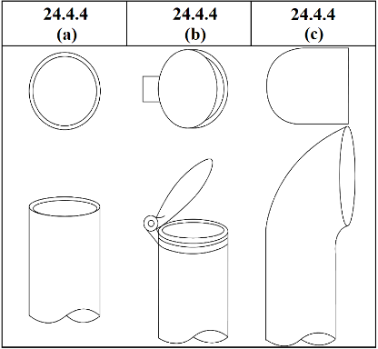
Figure 4: Typical Vertical Exhaust Outlet Configurations
25. TOILETS, URINALS, BASINS AND SINKS
25.1. No vehicle shall be equipped with a toilet or urinal the contents of which can be discharged directly onto the road.
25.2. Except in the case of a ‘Caravan’, every toilet or urinal pan must empty into a tank which is:
(a) carried by the vehicle; and
(b) efficiently ventilated by means of a pipe, the outlet of which is outside the vehicle.
25.3. Every tank into which a toilet or urinal pan empties must contain non‑inflammable and non‑irritant chemicals of such character and in such quantity as to form at all times an efficient deodorant and germicide in respect of the contents of the tank, toilet or urinal (as applicable).
25.4. No basin or sink shall drain into any toilet or urinal or into any tank into which a toilet or urinal empties.
25.5. Each toilet and/or urinal closet must vent directly to the atmosphere.
APPENDIX 1
Determination of the ‘Static Stability Ratio’ for category LE vehicles
- Definitions
- ‘Static Stability Ratio’ is the ratio of the height (h) of the ‘Centre of Mass (CoM)’ (see Figure 5) and the horizontal distance (d) from the ‘CoM’ to the nearest roll axis (see Figures 6 and 7) at ‘Maximum Loaded Test Mass’.
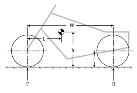
Figure 5: Three-wheeled L-Group vehicle (side view)
Figure 6: Category LEM1, LEP1 or LEG1 vehicle (plan view)
Figure 7: Category LEM2, LEP2 or LEG2 vehicle (plan view)
1.2. A ‘roll axis’ is a line joining the centre-point of each tyre’s contact patch (see Figures 6 and 7).
2. Procedures for determining the transverse location and the longitudinal location (L) of the ‘CoM’
2.1. Unless otherwise ‘Approved’, the transverse location of the ‘CoM’ shall be taken to be located along the vehicle’s longitudinal centreline.
2.2. Unless otherwise ‘Approved’, the longitudinal location (L) of the ‘CoM’ from the centreline of the front ‘Axle’, must be determined according to the formula:

Where:
W is the ‘Wheelbase’
R is the rear ‘Axle Load’ on the tyre(s) at ‘Maximum Loaded Test Mass’
F is the front ‘Axle Load’ on the tyre(s) at ‘Maximum Loaded Test Mass’
3. Procedures for determining the height (h) of the ‘CoM’
3.1. The height (h) of the ‘CoM’ must be determined according to either the Stable Pendulum Method (clause 3.2 below) or the Axle Lift Method (clause 3.3 below). The ‘Manufacturer’ may decide which method is used.
3.2. Stable Pendulum Method
3.2.1. For category LEM1, LEP1 and LEG1 vehicles:
(a) position the vehicle on a level surface;
(b) mark a horizontal ‘reference line’ parallel to the vehicle longitudinal centreline, passing through the centre of the rear ‘Axle’;
(c) chock both rear wheels;
(d) raise the front of the vehicle until the ‘CoM’ is directly over the rear ‘Axle’;
(e) measure the angle (θ) between the ‘reference line’ and the horizontal (see Figure 8); and
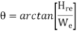
(f) determine the height (h) of the ‘CoM’ from the formula:
Where:
r is the rolling radius of the tyre(s) fitted to the rear wheel(s)
W is the ‘Wheelbase’
L is the longitudinal location of the ‘CoM’ from the centreline of the front ‘Axle’
θ is the angle between the ‘reference line’ and the horizontal

Figure 8: Stable Pendulum Method for a category LEM1, LEP1 or LEG1 vehicle
3.2.2. For category LEM2, LEP2 and LEG2 vehicles:
(a) position the vehicle on a level surface;
(b) mark a horizontal ‘reference line’ parallel to the vehicle longitudinal centreline, passing through the centre of the front ‘Axle’;
(c) chock both front wheels;
(d) raise the rear of the vehicle until the ‘CoM’ is directly over the front ‘Axle’;
(e) measure the angle (θ) between the ‘reference line’ and the horizontal (see Figure 9); and
(f) determine the height (h) of the ‘CoM’ from the formula:

Where:
r is the rolling radius of the tyres fitted to the front wheels
L is the longitudinal location of the ‘CoM’ from the centreline of the front ‘Axle’
θ is the angle (θ) between the ‘reference line’ and the horizontal
Figure 9: Stable Pendulum Method for a category LEM2, LEP2 or LEG2 vehicle
3.3. Axle Lift Method
3.3.1. Category LEM1, LEP1 and LEG1 vehicles
3.3.1.1 With the suspension blocked to prevent movement and the vehicle in the ‘Maximum Loaded Test Mass’ condition:
(a) use a block (or blocks) to elevate the front wheel by at least 600 mm (see Figure 10);
(b) determine the longitudinal location of the ‘CoM’ in the elevated state (Le), from the centreline of the front ‘Axle’, using the formula:

Where (see Figure 10):
We is the wheelbase in the horizontal plane
Re is the rear ‘Axle Load’ on the tyre(s) with the elevated vehicle in the ‘Maximum Loaded Test Mass’ condition = F + R – Fe
Fe is the front ‘Axle Load’ on the tyre(s) with the elevated vehicle in the ‘Maximum Loaded Test Mass’ condition = F + R – Re
F is the front ‘Axle Load’ on the tyre(s) with the vehicle on a level surface in the ‘Maximum Loaded Test Mass’ condition
R is the rear ‘Axle Load’ on the tyre(s) with the vehicle on a level surface in the ‘Maximum Loaded Test Mass’ condition
(c) determine the angle (θ) of inclination from the formula:

Where (see Figure 10):
Hfe is the height by which the front wheel is elevated
We is the wheelbase in the horizontal plane
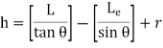
(d) determine the height (h) of the ‘CoM’ from the formula:
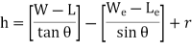
Where (see Figure 10):
W is the ‘Wheelbase’ of the vehicle measured prior to elevation; and
L is the longitudinal location of the ‘CoM’ prior to elevation (as determined according to clause 2.2 of this appendix above)
θ is the angle of inclination
We is the wheelbase in the horizontal plane
Le is the longitudinal location of the ‘CoM’ in the elevated state
r is the rolling radius of the tyres fitted to the rear wheels
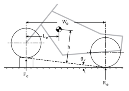
Figure 10: Axle Lift Method for a category LEM1, LEP1 or LEG1 vehicle
3.3.2. Category LEM2, LEP2 and LEG2 vehicles
3.3.2.1 With the suspension blocked to prevent movement and the vehicle in the ‘Maximum Loaded Test Mass’ condition:
(a) use a block (or blocks) to elevate the rear wheel by at least 600 mm (see Figure 11);
(b) determine the longitudinal location of the ‘CoM’ in the elevated state (Le), from the centreline of the front ‘Axle’, using the formula:
Where (see Figure 11):
We is the wheelbase in the horizontal plane
Re is the rear ‘Axle Load’ on the tyre(s) with the elevated vehicle in the ‘Maximum Loaded Test Mass’ condition = F + R – Fe
Fe is the front ‘Axle Load’ on the tyre(s) with the elevated vehicle in the ‘Maximum Loaded Test Mass’ condition = F + R – Re
F is the front ‘Axle Load’ on the tyre(s) with the vehicle on a level surface in the ‘Maximum Loaded Test Mass’ condition
R is the rear ‘Axle Load’ on the tyre(s) with the vehicle on a level surface in the ‘Maximum Loaded Test Mass’ condition
(c) determine the angle (θ) of declination from the formula:
Where (see Figure 11):
Hre is the height by which the rear wheel is elevated
We is the wheelbase in the horizontal plane
(d) determine the height (h) of the ‘CoM’ from the formula:
Where (see Figure 11):
L is the longitudinal location of the ‘CoM’ prior to elevation (as determined according to clause 2.2 of this appendix above)
θ is the angle of declination
We is the wheelbase in the horizontal plane
Le is the longitudinal location of the ‘CoM’ in the elevated state
r is the rolling radius of the tyres fitted to the rear wheels

Figure 11: Axle Lift Method for a category LEM2, LEP2 or LEG2 vehicle
4. Calculation of the horizontal distance (d) from the ‘CoM’ to the nearest ‘roll axis’
4.1. For category LEM1, LEP1 and LEG1 vehicles, the horizontal distance (d) from the ‘CoM’ to the nearest ‘roll axis’ shall be calculated from the formula shown below:
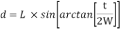
where:
L is the longitudinal location of the ‘CoM’ from the centreline of the front ‘Axle’
t is the width of the wheel track of the rear ‘Axle’
W is the ‘Wheelbase’
4.2. For category LEM2, LEP2 and LEG2 vehicles, the horizontal distance (d) from the ‘CoM’ to the nearest ‘roll axis’ shall be calculated from the formula shown below:

where:
W is the ‘Wheelbase’
L is the longitudinal location of the ‘CoM’ from the centreline of the front ‘Axle’
t is the width of the wheel track of the front ‘Axle’
5. Calculation of the ‘Static Stability Ratio’
5.1. The ‘Static Stability Ratio’ shall be calculated as follows:
‘Static Stability Ratio’ = h/d
where:
h is the height (h) of the ‘CoM’
d is the horizontal distance from the ‘CoM’ to the nearest ‘roll axis’
5.2. The test report must take account of known and potential inaccuracies in measurement equipment, especially where the ‘Static Stability Ratio’ nears the compliance limit.
5.2.1. For the Stable Pendulum Method, the test facility must be able to accurately measure the angle (θ) between the reference line and the horizontal.
5.2.2. For the Axle Lift Method, the test facility must be able to accurately measure the height of elevation of the single-wheel axle, and accurately measure the ‘Axle Load’ (or axle weight) of the two-wheel axle.