UN Regulation No. 125
Uniform provisions concerning the approval of motor vehicles with regard to the forward field of vision of the motor vehicle driver
Contents
Page
Regulation
1. Scope ............................................................ 9
2. Definitions for the purpose of this Regulation .................................. 9
3. Application for approval ............................................... 11
4. Approval .......................................................... 11
5. Specifications ...................................................... 12
6. Test procedure ...................................................... 17
7. Modification of vehicle type and extension of approval ........................... 18
8. Conformity of production ............................................... 18
9. Penalties for non-conformity of production ................................... 18
10. Production definitively discontinued ........................................ 19
11. Names and addresses of Technical Services responsible for conducting approval tests, and of Type Approval Authorities 19
12. Transitional provisions................................................. 19
Annexes
1 Communication ..................................................... 20
2 Arrangements of approval marks ......................................... 22
3 Procedure for determining the "H" point and the actual torso angle for seating positions in
motor vehicles..................................................... 23
Appendix 1: Description of the three-dimensional "H" point machine (3-D H machine)..... 23
Appendix 2: Three-dimensional reference system .............................. 23
Appendix 3: Reference data concerning seating positions ......................... 23
4 Method for determining the dimensional relationships between the vehicle's primary reference
marks and the three-dimensional reference grid ............................... 24
Appendix ........................................................ 25
1. Scope
1.1. This Regulation applies to the 180° forward field of vision of drivers of category M1 vehicles.
1.2. Its purpose is to ensure an adequate field of vision when the windscreen and other glazed surfaces are dry and clean.
1.3. The requirements of this Regulation are so worded as to apply to category M1 vehicles in which the driver is on the left. In category M1 vehicles in which the driver is on the right these requirements shall be applied by inverting the criteria, when appropriate.
2. Definitions for the purpose of this Regulation
2.1. "Approval of a vehicle type" means the full procedure whereby a Contracting Party to the Agreement certifies that a vehicle type meets the technical requirements of this Regulation.
2.2. "Vehicle type with regard to the field of vision" means vehicles which do not differ in such essential aspects as:
2.2.1. The external and internal forms and arrangements within the area specified in paragraph 1. above which may affect visibility; and
2.2.2. The shape and dimensions of the windscreen and its mounting.
2.3. "Three‑dimensional reference grid" means a reference system which consists of a vertical longitudinal plane X‑Z, a horizontal plane X‑Y and a vertical transverse plane Y‑Z (see Annex 4, Appendix, Figure 6); the grid is used to determine the dimensional relationships between the position of design points on drawings and their positions on the actual vehicle. The procedure for situating the vehicle relative to the grid is specified in Annex 4; all coordinates referred to ground zero shall be based on a vehicle in running order plus one front-seat passenger, the mass of the passenger being 75 kg ±1 per cent.
2.3.1. Vehicles fitted with suspension enabling their ground clearance to be adjusted shall be tested under the normal conditions of use specified by the vehicle manufacturer.
2.4. "Primary reference marks" means holes, surfaces, marks and identification signs on the vehicle body. The type of reference mark used and the position of each mark relative to the X, Y and Z coordinates of the three‑dimensional reference grid and to a design ground plane shall be specified by the vehicle manufacturer. These marks may be the control points used for body‑assembly purposes.
2.5. "Seat‑back angle" means the angle defined in the revised Consolidated Resolution on the Construction of Vehicles (R.E.3), Annex 1, paragraph 2.6. or 2.7.
2.6. "Actual seat‑back angle" means the angle defined in the revised R.E.3, Annex 1, paragraph 2.6.
2.7. "Design seat‑back angle" means the angle defined in the revised R.E.3, Annex 1, paragraph 2.7.
2.8. "V points" means points whose position in the passenger compartment is determined as a function of vertical longitudinal planes passing through the centres of the outermost designated seating positions on the front seat and in relation to the "R" point and the design angle of the seat‑back, which points are used for verifying compliance with the field of vision requirements.
2.9. "R point or seating reference point" means the point defined in the revised R.E.3, Annex 1, paragraph 2.4.
2.10. "H point" means the point defined in the revised R.E.3, Annex 1, paragraph 2.3.
2.11. "Windscreen datum points" means points situated at the intersection with the windscreen of lines radiating forward from the V points to the outer surface of the windscreen.
2.12. "Armoured vehicle" means a vehicle intended for the protection of conveyed passengers and/or goods and complying with armour plating anti-bullet requirements.
2.13. "Transparent area" means that area of a vehicle windscreen or other glazed surface whose light transmittance measured at right angles to the surface is not less than 70 per cent. In the case of armoured vehicles, the light transmittance factor is not less than 60 per cent.
2.14. "P points" means the points about which the driver's head rotates when he views objects on a horizontal plane at eye level.
2.15. "E points" means points representing the centres of the driver's eyes and used to assess the extent to which "A" pillars obscure the field of vision.
2.16. "A pillar" means any roof support forward of the vertical transverse plane located 68 mm in front of the V points and includes non‑transparent items such as windscreen mouldings and door frames, attached or contiguous to such a support.
2.17. "Horizontal seat‑adjustment range" means the range of normal driving positions designated by the vehicle manufacturer for the adjustment of the driver's seat in the direction of the X axis (see paragraph 2.3. above).
2.18. "Extended seat‑adjustment range" means the range designated by the vehicle manufacturer for the adjustment of the seat in the direction of the X axis (see paragraph 2.3. above) beyond the range of normal driving positions specified in paragraph 2.17. above and used for converting seats into beds or facilitating entry to the vehicle.
3. Application for approval
3.1. The application for approval of a vehicle type with regard to the driver's field of vision shall be submitted by the vehicle manufacturer or by his authorized representative.
3.2. It shall be accompanied by the documents mentioned below in triplicate and include the following particulars:
3.2.1. A description of the vehicle type with regard to the items mentioned in paragraph 2.2. above, together with dimensional drawings and either a photograph or an exploded view of the passenger compartment. The numbers and/or symbols identifying the vehicle type shall be specified; and
3.2.2. Particulars of the primary reference marks in sufficient detail to enable them to be readily identified and the position of each in relation to the others and to the "R" point verified.
3.3. A vehicle representative of the vehicle type to be approved shall be submitted to the Technical Service conducting the approval tests.
4. Approval
4.1. If the vehicle type submitted for approval pursuant to this Regulation meets the requirements of paragraph 5. below, approval of that vehicle shall be granted.
4.2. An approval number shall be assigned to each type approved. Its first two digits (at present 01 for the Regulation in its current form) shall indicate the series of amendments incorporating the most recent major technical amendments made to the Regulation at the time of issue of the approval. The same Contracting Party shall not assign the same number to the same vehicle type equipped with another type of field of vision, or to another vehicle type.
4.3. Notice of approval or of refusal or withdrawal of approval pursuant to this Regulation shall be communicated to the Parties to the Agreement which apply this Regulation by means of a form conforming to the model in Annex 1 and photographs and/or plans supplied by the applicant being in a format not exceeding A4 (210 x 297 mm), or folded to that format, and on an appropriate scale.
4.4. There shall be affixed, conspicuously and in a readily accessible place specified on the approval form, to every vehicle conforming to a vehicle type approved under this Regulation, an international approval mark conforming to the model described in Annex 2 to this Regulation, consisting of:
4.4.1. A circle surrounding the letter "E" followed by the distinguishing number of the country, which has granted approval;
4.4.2. The number of this Regulation, followed by the letter "R", a dash and the approval number to the right of the circle prescribed in paragraph 4.4.1. above.
4.5. If the vehicle conforms to a vehicle type approved under one or more other Regulations, annexed to the Agreement, in the country, which has granted approval under this Regulation, the symbol prescribed in paragraph 4.4.1. above need not be repeated; in such a case, the Regulation and approval numbers and the additional symbols shall be placed in vertical columns to the right of the symbol prescribed in paragraph 4.4.1. above.
4.6. The approval mark shall be clearly legible and be indelible.
4.7. The approval mark shall be placed close to or on the vehicle data plate.
5. Specifications
5.1. Driver's field of vision.
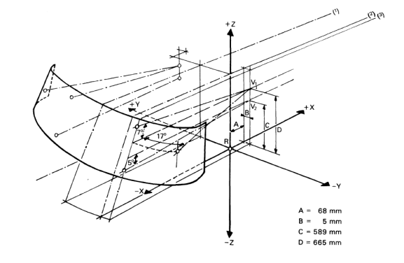
5.1.1. The transparent area of the windscreen shall include at least the windscreen datum points (see Annex 4, Appendix, Figure 1):
5.1.1.1. A horizontal datum point forward of V1 and 17° to the left (see Annex 4, Appendix, Figure 1);
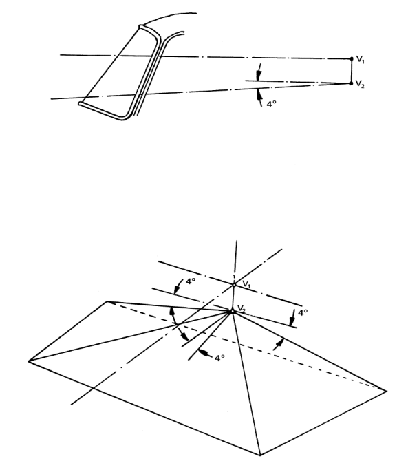
5.1.1.2. An upper vertical datum point forward of V1 and 7° above the horizontal;
5.1.1.3. A lower vertical datum point forward of V2 and 5° below the horizontal;
5.1.1.4. To verify compliance with the forward-vision requirement on the opposite half of the windscreen, three additional datum points, symmetrical to the points defined in paragraphs 5.1.1.1. to 5.1.1.3. above in relation to the median longitudinal plane of the vehicle, are obtained.
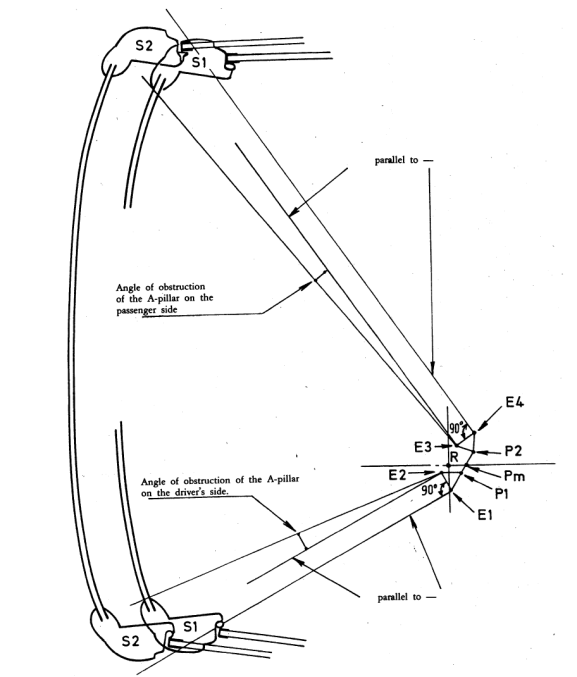
5.1.2. The angle of obstruction for each "A" pillar, as described in paragraph 5.1.2.1. below, shall not exceed 6° (see Annex 4, Appendix, Figure 3). In the case of armoured vehicles, that angle shall not exceed 10°.
The angle of obstruction of the "A" pillar on the passenger side, as defined in paragraph 5.1.2.1.2. below, need not be determined if the two pillars are located symmetrically in relation to the median longitudinal vertical plane of the vehicle.
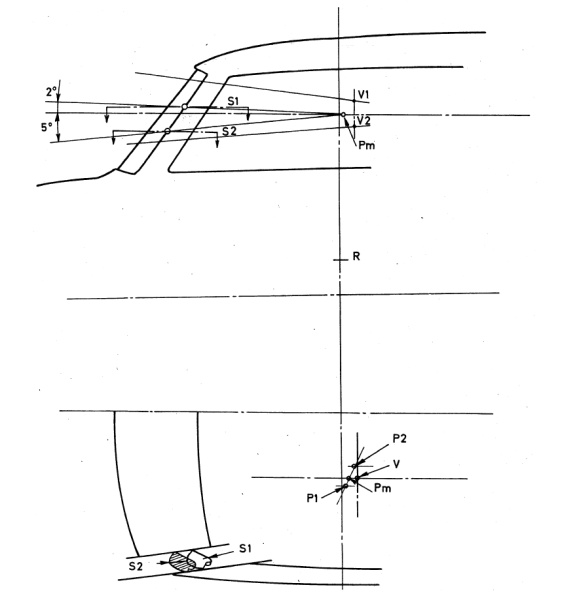
5.1.2.1. The angle of obstruction of each "A" pillar shall be measured by superimposing in a plane the following two horizontal sections:
Section 1: Starting from the Pm point situated at the location defined in paragraph 5.3.1.1. below, draw a plane forming an angle of 2° upwards in relation to the horizontal plane passing forward through Pm. Determine the horizontal section of the "A" pillar starting from the foremost point of the intersection of the "A" pillar and the inclined plane (see Annex 4, Appendix, Figure 2).
Section 2: Repeat the same procedure, taking a plane declining at an angle of 5° downwards in relation to the horizontal plane passing forward through Pm (see Annex 4, Appendix, Figure 2).
5.1.2.1.1. The angle of obstruction of the "A" pillar on the driver's side is the angle formed on the plane view by a parallel, starting from E2, to the tangent joining E1 with the outer edge of section S2 and the tangent joining E2 to the inner edge of section S1 (see Annex 4, Appendix, Figure 3).
5.1.2.1.2. The angle of obstruction of the "A" pillar on the passenger side is the angle formed on the plane view by the tangent joining E3 to the inner edge of section S1 and a parallel, starting from E3, to the tangent joining E4 to the outer edge of section S2 (see Annex 4, Appendix, Figure 3).
5.1.2.2. No vehicle shall have more than two "A" pillars.
5.1.3. Except as provided in paragraph 5.1.3.3. or 5.1.3.4. below, other than the obstructions created by the "A" pillars, the fixed or movable vent or side window division bars, outside radio aerials, devices for indirect vision, covering the mandatory field of indirect vision, and windscreen wipers, there shall be no obstruction in the driver's 180° forward direct field of vision below a horizontal plane passing through V1, and above three planes through V2, one being perpendicular to the plane X‑Z and declining forward 4° below the horizontal, and the other two being perpendicular to the plane Y‑Z and declining 4° below the horizontal (see Annex 4, Appendix, Figure 4).
The following are not considered to be obstructions to the field of vision:
(a) Embedded or printed "radio aerial" conductors, no wider than the following:
(i) Embedded conductors: 0.5 mm,
(ii) Printed conductors: 1.0 mm. These "radio aerial" conductors shall not cross zone A. However, three "radio aerial" conductors may cross zone A if their width does not exceed 0.5 mm.
(b) Within zone A located "defrosting/demisting" normally in "zigzag" or sinusoidal form having the following dimensions:
(i) Maximum visible width: 0.030 mm,
(ii) Maximum conductor density:
a. If the conductors are vertical: 8/cm,
b. If the conductors are horizontal: 5/cm.
5.1.3.1. In case of camera monitor devices, the exemptions of paragraph 5.1.3. apply to cameras including their holders and housings which are mounted to the vehicle exterior. The camera-monitor system replacing a rear-view Class I mirror shall have the same exemption.
5.1.3.2. For vehicles, which are equipped as standard with approved rear-view mirrors that are optionally replaced by camera-monitor devices, the exemptions of paragraph 5.1.3. apply also to monitors, provided:
(a) Their obstruction of the direct view does not exceed the level of obstruction of the corresponding exterior rear-view mirror including its housing and holder, and;
(b) The position of the monitor is as close as practicable to the position of the rear-view mirror it replaces.
5.1.3.3. An obstruction created by the steering-wheel rim and the instrument panel inside the steering wheel will be tolerated if a plane through V2, perpendicular to the plane x - z and tangential to the highest part of the steering-wheel rim, is declined at least 1° below the horizontal.
The steering wheel, if adjustable, shall be placed in the normal position indicated by the manufacturer or, failing that, midway between the limits of its range(s) of adjustment.
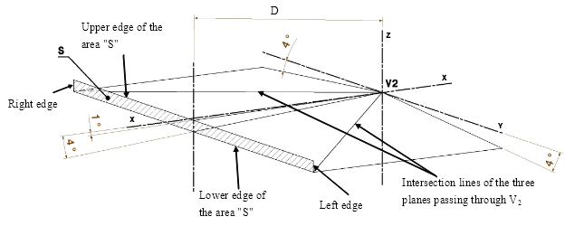
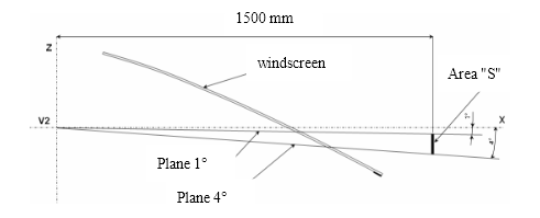
5.1.3.4. An obstruction between a plane through V2, and declined at least 1° below the horizontal and a plane through V2 and declined 4° below the horizontal will be tolerated if the conical projection of this obstruction, starting from V2, on an area "S" as defined in paragraph 5.1.3.2.1. below does not exceed 20 per cent of this area. The steering wheel, if adjustable, shall be placed in the normal position indicated by the manufacturer or, failing that, midway between the limits of its range(s) of adjustment.
5.1.3.4.1. The area "S" (see Annex 4, Appendix, Figure 7) is a rectangular vertical area located in a plane perpendicular to the X coordinate 1,500 mm forward of the point V2. The upper edge of the area "S" is defined by a plane passing through V2 declined forward 1° below the horizontal. The lower edge of the area "S" is defined by a plane passing through V2 declined forward 4° below the horizontal. The left and right edges of the area "S" are vertical and generated from the intersection lines of the three planes declined 4° as defined in paragraph 5.1.2.2. above.
5.1.3.4.2. In the case of a windscreen extending beyond 1,500 mm forward of the point V2, the distance between the area "S" and the point V2 may be extended accordingly.
5.1.4. In the case where the height of V2 above the ground exceeds 1,650 mm, the following requirement shall be met:
A 1,200 mm tall cylindrical object with a diameter of 300 mm that is situated inside the space bounded by a vertical plane located 2,000 mm in front of the vehicle, a vertical plane located 2,300 mm in front of the vehicle, a vertical plane located 400 mm from the driver's side of the vehicle, and a vertical plane located 600 mm from the opposite side of the vehicle shall be at least partially visible when viewed directly from V2 (see Figure 1), regardless of where the object is within that space, unless it is invisible due to a blind spot(s) created by the A pillars, windscreen wipers, or steering wheel.
If the driver's seat is located in the central driving position of the vehicle, the 1,200 mm tall cylindrical object shall be situated inside the space bounded by a vertical plane located 2,000 mm in front of the vehicle, a vertical plane located 2,300 mm in front of the vehicle, a vertical plane located 500 mm from the side of the vehicle (see Figure 2).
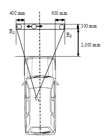
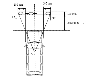 Figure 1 Figure 2


5.2. Position of the V points
5.2.1. The position of the V points in relation to the "R" point, as indicated by XYZ coordinates from the three dimensional reference grid, are as shown in Tables I and IV.
5.2.2. Table I indicates the basic coordinates for a design seat-back angle of 25°. The positive direction for the coordinates is indicated in Annex 4, Appendix, Figure 1.
V-point | X | Y | Z |
V1 | 68 mm | -5 mm | 665 mm |
V2 | 68 mm | -5 mm | 589 mm |
5.3. Position of the P points
5.3.1. The position of the P points in relation to the "R" point, as indicated by the XYZ coordinates from the three-dimensional reference grid, are as shown by Tables II, III and IV.
5.3.1.1. Table II sets out the base coordinates for a design seat-back angle of 25°. The positive direction of the coordinates is set out in Annex 4, Appendix, Figure 1.
The Pm point is the point of intersection between the straight line joining P1, P2 and the longitudinal vertical plane passing through the "R" point.
Point P | X | Y | Z |
P1 | 35 mm | -20 mm | 627 mm |
P2 | 63 mm | 47 mm | 627 mm |
Pm | 43.36 mm | 0 mm | 627 mm |
5.3.1.2. Table III indicates the further corrections to be made to the X coordinates of P1 and P2 when the horizontal seat-adjustment range as defined in paragraph 2.16. above exceeds 108 mm. The positive direction for the coordinates is indicated in Annex 4, Appendix, Figure 1.
Horizontal seat-adjustment range | Δx |
108 to 120 mm | -13 mm |
121 to 132 mm | -22 mm |
133 to 145 mm | -32 mm |
146 to 158 mm | -42 mm |
more than 158 mm | -48 mm |
5.4. Correction for design seat-back angles other than 25°
Table IV indicates the further corrections to be made to the X and Z coordinates of each P point and each V point when the design seat-back angle is not 25°. The positive direction for the coordinates is indicated in Annex 4, Appendix, Figure 1.
Seat-back angle
(in °) | Horizontal coordinates
Δx | Vertical coordinates
Δz | Seat-back angle
(in °) | Horizontal coordinates
Δx | Vertical coordinates
Δz |
5 | -186 mm | 28 mm | 23 | -18 mm | 5 mm |
6 | -177 mm | 27 mm | 24 | -9 mm | 3 mm |
7 | -167 mm | 27 mm | 25 | 0 mm | 0 mm |
8 | -157 mm | 27 mm | 26 | 9 mm | -3 mm |
9 | -147 mm | 26 mm | 27 | 17 mm | -5 mm |
10 | -137 mm | 25 mm | 28 | 26 mm | -8 mm |
11 | -128 mm | 24 mm | 29 | 34 mm | -11 mm |
12 | -118 mm | 23 mm | 30 | 43 mm | -14 mm |
13 | -109 mm | 22 mm | 31 | 51 mm | -18 mm |
14 | -99 mm | 21 mm | 32 | 59 mm | -21 mm |
15 | -90 mm | 20 mm | 33 | 67 mm | -24 mm |
16 | -81 mm | 18 mm | 34 | 76 mm | -28 mm |
17 | -72 mm | 17 mm | 35 | 84 mm | -32 mm |
18 | -62 mm | 15 mm | 36 | 92 mm | -35 mm |
19 | -53 mm | 13 mm | 37 | 100 mm | -39 mm |
20 | -44 mm | 11 mm | 38 | 108 mm | -43 mm |
21 | -35 mm | 9 mm | 39 | 115 mm | -48 mm |
22 | -26 mm | 7 mm | 40 | 123 mm | -52 mm |
5.5. Position of the E points
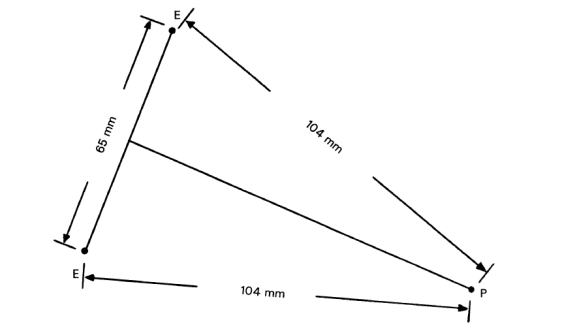
5.5.1. E1 and E2 points are each 104 mm from P1.
E2 is 65 mm from E1 (see Annex 4, Appendix, Figure 4).
5.5.2. The straight line joining E1 and E2 is rotated about P1 until the tangent joining E1 to the outer edge of Section 2 of the "A" pillar on the driver's side is normal to the straight line E1 - E2 (see Annex 4, Appendix, Figure 3).
5.5.3. E3 and E4 are each 104 mm from point P2. E3 is 65 mm from E4 (see Annex 4, Appendix, Figure 4).
5.5.4. The straight line E3 - E4 is rotated about P2 until the tangent joining E4 to the outer edge of Section 2 of the "A" pillar on the passenger's side is normal to the straight line E3 - E4 (see Annex 4, Appendix, Figure 3).
6. Test procedure
6.1. Driver's field of vision
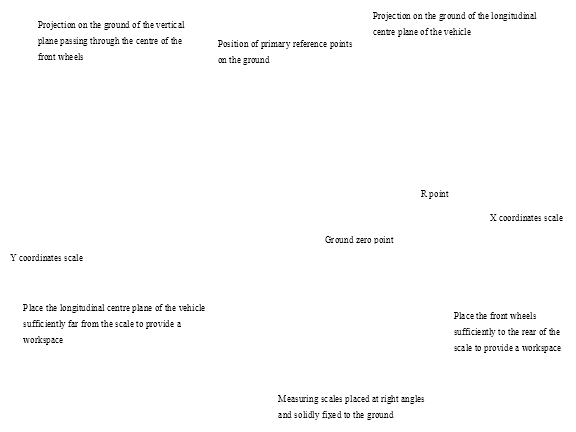
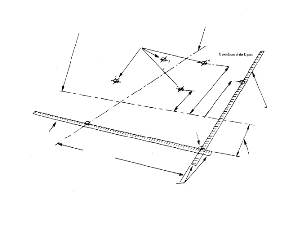
6.1.1. The dimensional relationships between the vehicle's primary reference marks and the three - dimensional reference grid shall be determined by the procedure prescribed in Annex 4.
6.1.2. The position of the points V1 and V2 is determined in relation to the "R" point as indicated by the XYZ coordinates of the three‑dimensional reference grid and are shown in Table I under paragraph 5.2.2. above and Table IV under paragraph 5.4. above. The windscreen datum points shall then be found from the corrected V points as prescribed in paragraph 5.1.1. above.
6.1.3. The relationship between the P points, the "R" point, and the centre‑line of the driver's seating position, as indicated by XYZ coordinates from the three‑dimensional reference grid, shall be determined from Tables II and III in paragraph 5.3. above. The correction for design seat‑back angles other than 25° is shown in Table IV under paragraph 5.4. above.
6.1.4. The angle of obstruction (see paragraph 5.1.2. above) shall be measured in the inclined planes, as indicated in Annex 4, Appendix, Figure 2. The relationship between P1 and P2, which are connected to E1 and E2 and E3 and E4 respectively, is shown in Annex 4, Appendix, Figure 5.
6.1.4.1. Straight line E1 - E2 shall be set as described in paragraph 5.5.2. above. The angle of obstruction of the "A" pillar on the driver's side shall be measured as specified in paragraph 5.1.2.1.1. above.
6.1.4.2. Straight line E3 - E4 shall be set as described in paragraph 5.5.4. above. The angle of obstruction of the "A" pillar on the passenger side shall then be measured as specified in paragraph 5.1.2.1.2. above.
6.1.5. The manufacturer may measure the angle of obstruction either on the vehicle or in the drawings. In the event of doubt, the Technical Services may require the tests be carried out on the vehicle.
7. Modification of vehicle type and extension of approval
7.1. Every modification of the vehicle type as defined in paragraph 2.2. above shall be notified to the Type Approval Authority which approved the vehicle type. The Type Approval Authority may then either:
7.1.1. Consider that the modifications made do not have an adverse effect on the conditions of the granting of the approval and grant an extension of approval;
7.1.2. Consider that the modifications made affect the conditions of the granting of the approval and require further tests or additional checks before granting an extension of approval.
7.2. Confirmation or refusal of approval, specifying the alterations, shall be communicated by the procedure specified in paragraph 4.3. above to the Contracting Parties to the Agreement which apply this Regulation.
7.3. The Type Approval Authority shall inform the other Contracting Parties of the extension by means of the communication form which appears in Annex 2 to this Regulation. It shall assign a serial number to each extension, to be known as the extension number.
8. Conformity of production
8.1. Procedures concerning conformity of production shall conform to the general provisions defined in Schedule 1 to the Agreement (E/ECE/TRANS/505/Rev.3) and meet the following requirements:
8.2. A vehicle approved pursuant to this Regulation shall be so manufactured as to conform to the type approved by meeting the requirements of paragraph 5. above;
8.3. The Type Approval Authority, which has granted approval, may at any time verify the conformity of control methods applicable to each production unit. The normal frequency of such inspections shall be once every two years.
9. Penalties for non‑conformity of production
9.1. The approval granted in respect of a vehicle type pursuant to this Regulation may be withdrawn if the requirements laid down in paragraph 8. above are not complied with.
9.2. If a Contracting Party withdraws an approval it had previously granted, it shall forthwith so notify the other Contracting Parties applying this Regulation by sending them a communication form conforming to the model in Annex 1 to this Regulation.
10. Production definitively discontinued
If the holder of the approval completely ceases to manufacture a type of vehicle approved in accordance with this Regulation, he shall so inform the Type Approval Authority which granted the approval, which in turn shall forthwith inform the other Contracting Parties to the Agreement applying this Regulation by means of a communication form conforming to the model in Annex 1 to this Regulation.
11. Names and addresses of the Technical Services responsible for conducting approval tests and of Type Approval Authorities
The Contracting Parties to the Agreement applying this Regulation shall communicate to the United Nations Secretariat the names and addresses of the Technical Services responsible for conducting approval tests and of the Type Approval Authorities, which grant approval, and to which forms certifying approval or extension or refusal or withdrawal of approval are to be sent.
12. Transitional provisions
12.1. As from the official date of entry into force of the 01 series of amendments, no Contracting Party applying this Regulation shall refuse to grant approval under this Regulation as amended by the 01 series of amendments.
12.2. As from 24 months after the date of entry into force of the 01 series of amendments to this Regulation, Contracting Parties applying this Regulation shall grant approvals only if the vehicle type to be approved meets the requirements of this Regulation as amended by the 01 series of amendments.
12.3. Contracting Parties applying this Regulation shall not refuse to grant extensions of approvals for existing types, which have been granted according to the original version of this Regulation.
12.4. Even after the entry into force of the 01 series of amendments to this Regulation, type approvals of the vehicles to the original version of this Regulation shall remain valid. Contracting Parties applying this Regulation shall continue to accept them.
12.5. Notwithstanding the transitional provisions above, Contracting Parties whose application of this Regulation comes into force after the date of entry into force of the 01 series of amendments are not obliged to accept approvals, which were granted in accordance with the original version of this Regulation.