Vehicle Standard (Australian Design Rule 80/04 – Emission Control for Heavy Vehicles) 2023
I, CATHERINE KING, Minister for Infrastructure, Transport, Regional Development and Local Government, determine this national road vehicle standard under section 12 of the Road Vehicle Standards Act 2018.
Dated: 14 February 2023
[SIGNED]
Catherine King
Minister for Infrastructure, Transport, Regional Development and Local Government
1. LEGISLATIVE PROVISIONS
1.1. Name of Standard
1.1.1. This standard is the Vehicle Standard (Australian Design Rule 80/04 – Emission Control for Heavy Vehicles) 2023.
1.1.2. This standard may also be cited as Australian Design Rule 80/04 – Emission Control for Heavy Vehicles, the Australian Design Rule 80/04, or ADR 80/04.
1.2. Commencement
1.2.1. This standard commences on the day after it is registered.
2. FUNCTION
2.1. The function of this vehicle standard is to set exhaust emissions requirements for internal combustion engines used in heavy vehicles to reduce to burden of disease caused by air pollution.
3. APPLICABILITY
3.1. This vehicle standard applies to all MA, MB, MC and MD category vehicles with a gross vehicle mass greater than 3,500kg and all ME, NB, and NC category vehicles from the dates set out in clauses 3.1.1 to 3.1.2 and the table under clause 3.3 below.
3.1.1. 1 November 2024 for all new model vehicles.
3.1.2. 1 November 2025 for all vehicles.
3.2. For the purposes of clause 3.1.1 above, a “new model” is a vehicle model first produced with a ‘Date of Manufacture’ on or after the agreed date in that clause.
3.3. Applicability Table
Vehicle Category | ADR Category Code | UN Category Code[*] | Manufactured on or After[**] | Acceptable Prior Rules |
Moped 2 wheels | LA | L1 | Not Applicable | |
Moped 3 wheels | LB | L2 | Not Applicable | |
Motor cycle | LC | L3 | Not Applicable | |
Motor cycle and sidecar | LD | L4 | Not Applicable | |
Motor tricycle | LE | L5 | | |
| LEM | | Not Applicable | |
| LEP | | Not Applicable | |
| LEG | | Not Applicable | |
Passenger car | MA | M1 | 1 November 2024 | Nil |
Forward-control passenger vehicle | MB | M1 | 1 November 2024 | Nil |
Off-road passenger vehicle | MC | M1 | 1 November 2024 | Nil |
Light omnibus | MD | M2 | | Nil |
| up to 3.5 tonnes ‘GVM’ and up to 12 seats | MD1 | | Not Applicable | |
| up to 3.5 tonnes ‘GVM’ and more than 12 seats | MD2 | | Not Applicable | |
| over 3.5 tonnes and up to 4.5 tonnes ‘GVM’ | MD3 | | 1 November 2024 | Nil |
| over 4.5 tonnes and up to 5 tonnes ‘GVM’ | MD4 | | 1 November 2024 | Nil |
Heavy omnibus | ME | M3 | 1 November 2024 | Nil |
Light goods vehicle | NA | N1 | Not Applicable | |
Medium goods vehicle | NB | N2 | | Nil |
| over 3.5 tonnes up to 4.5 tonnes ‘GVM’ | NB1 | | 1 November 2024 | Nil |
| over 4.5 tonnes up to 12 tonnes ‘GVM’ | NB2 | | 1 November 2024 | Nil |
Heavy goods vehicle | NC | N3 | 1 November 2024 | Nil |
Very light trailer | TA | O1 | Not Applicable | |
Light trailer | TB | O2 | Not Applicable | |
Medium trailer | TC | O3 | Not Applicable | |
Heavy trailer | TD | O4 | Not Applicable | |
3.4 To the extent of any inconsistency, the applicability dates specified in clauses 3.1.1 and 3.1.2 apply in lieu of any dates specified in Appendix A.
4. DEFINITIONS
4.1. For vehicle categories, definitions and meanings used in this standard, refer to:
4.1.1. Vehicle Standard (Australian Design Rule – Definitions and Vehicle Categories) 2005; and
4.1.2. Definitions in Appendix A of this standard.
4.2 For the purposes of Clause 5.1:
4.2.1 ‘Battery Electric Vehicle’ means a vehicle propelled exclusively by one or more electric motors drawing current from a rechargeable energy storage system.
4.2.2 ‘Hydrogen Fuel Cell Vehicle’ means a vehicle propelled exclusively by one or more electric motors powered by a fuel cell transforming hydrogen into electrical energy.
5. REQUIREMENTS
5.1. Subject to 5.1.1 and 5.1.2, all vehicles must comply with either:
a) the requirements of Appendix A, as varied by Section 6 - Exemptions and Alternative Procedures; or
b) the technical requirements of one of the alternative standards set out in Section 7
5.1.1 Battery Electric Vehicles need not comply with the requirements of clause 5.1, if the vehicle is fitted with a label or other emblem indicating the vehicle is a ‘Battery Electric Vehicle’ or BEV.
5.1.2 Hydrogen Fuel Cell Vehicles need not comply with the requirements of clause 5.1, if the vehicle is fitted with a label or other emblem indicating the vehicle is a ‘Hydrogen Fuel Cell Vehicle’ or HFCV.
6. EXEMPTIONS AND ALTERNATIVE PROCEDURES
6.1. Compliance with the following parts, sections and annexes of Appendix A is not required for the purposes of this standard:
Section 3 Application for Approval
Section 4 Approval
Section 8 Conformity of production
Section 9 Conformity of in-service vehicles/engines
Section 10 Penalties for non-conformity of production
Section 11 Modification and extension of approval of the approved type
Section 12 Production definitively discontinued
Section 13 Transitional provisions
Section 14 Names and addresses of Technical Services responsible for conducting approval tests and of Type Approval Authorities
Appendix 1 Procedure for production conformity testing when standard deviation is satisfactory
Appendix 2 Procedure for production conformity testing when standard deviation is unsatisfactory or unavailable
Appendix 3 Procedure for production conformity testing at manufacturer's request
Appendix 4 Summary of approval process for engines fuelled with natural gas, engines fuelled with LPG and dual-fuel engines fuelled with natural gas/biomethane or LPG
Annexes
Annex 1 Models of information document
Annex 2A Communication concerning the approval of an engine type or family as a separate technical unit with regard to the emission of pollutants pursuant to Regulation No. 49, 07 series of amendments
Addendum to type approval communication No … concerning the type approval of an engine type or family as a separate technical unit with regard to exhaust emissions pursuant to Regulation No. 49, 07 series of amendments
Annex 2B Communication concerning the approval of a vehicle type with an approved engine with regard to the emission of pollutants pursuant to Regulation No. 49, 07 series of amendments
Annex 2C Communication concerning the approval of a vehicle type with regard to the emission of pollutants pursuant to Regulation No. 49, 07 series of amendments
Addendum to type approval communication No … concerning the type approval of a vehicle type with regard to the emission of pollutants pursuant to Regulation No. 49, 07 series of amendments
Annex 2D AES Documentation Package
Annex 3 Arrangements of approval marks
Annex 13 Type approval of replacement pollution control devices as separate technical unit
6.2 Engines fitted with a heated reagent tank and dosing system may comply with the requirements applicable to non-heated reagent tanks and dosing systems in Clause 2.4.3 of Annex 11 in lieu of the requirements applicable to heated reagent tanks and dosing systems in Clause 2.4.2 of Annex 11.
6.3 The on board diagnostic system must comply with:
(a) if the vehicle is fitted with a compression ignition or dual-fuel engine:
(i) the PM Mass OTL monitoring requirements as set out in the row "general requirements" of Table 1 of Annex 9A of Appendix A; and
(ii) the NOx OTL monitoring requirements as set out in the row "general requirements" of Table 1 of Annex 9A of Appendix A.
(b) if the vehicle is fitted with a positive ignition engine: the NOx and CO OTL monitoring requirements as set out in the row "general requirements" of Table 2 of Annex 9A of Appendix A.
(c) if the vehicle is fitted with an engine that uses a consumable reagent to reduce emissions: the reagent quality and consumption "general" requirements as set out in paragraphs 7.1.1. and 8.4.1. of Annex 11 of Appendix A.
6.4 The documentation required in the following parts of Appendix A is not required to be submitted in an application to obtain a road vehicle type approval or component type approval to this vehicle standard under Section 16 or 174 of the Road Vehicle Standards Rules, but must be kept by the applicant as part of the supporting information required under Sections 30 and 187 of the Road Vehicle Standards Rules and supplied to the Department on request to ascertain compliance with the technical requirements of this vehicle standard in accordance with Sections 29 and 186 of the Road Vehicle Standards Rules:
Section 5.1.4
Section 5.5;
Section 3.4 of Annex 7;
Sections 6.4 and 6.5 of Annex 9A
Section 1.6 of Annex 9A - Appendix 1;
Sections 4.7.1.4, 4.7.2, 6.3 and 8 of Annex 9B
Section 11 of Annex 10
Section 2.2 of Annex 11
Section A1.1 of Annex 11 – Appendix 1
Annex 11 – Appendix 4
Section 1 of Annex 14
Section 11 of Annex 15
6.5 For the purposes of the PEMS test required by Annex 10 of Appendix A:
(a) compliance may be demonstrated by testing a representative vehicle configuration for that vehicle type with a gross combination mass up to 70 tonnes;
(b) vehicles/engine families need not comply with the maximum allowed conformity factor for particle number in Table 2 of Clause 6.3.
6.6 Except where referenced in Annex 10 of Appendix A, compliance with Annex 8 of Appendix A is not required for the purposes of this vehicle standard.
6.7 The test procedures specified in Amendment 3 and Amendment 4 to United Nations Global Technical Regulation No. 4 United Nations Global Technical Regulation on Test procedure for compression ignition (C.I.) engines and positive-ignition (P.I.) engines fuelled with natural gas (NG) or liquefied petroleum gas (LPG) with regard to the emission of pollutants (WHTC) may be used to demonstrate compliance with the requirements of Clause 5.3 of Appendix A for a hybrid engine/driveline in lieu of the test procedures specified in Appendices 1 to 6 of Annex 4 of Appendix A.
7. ALTERNATIVE STANDARDS
UN Regulation No. 49
7.1. Subject to Clauses 7.1.1 to 7.1.5, the technical requirements of United Nations Regulation No. 49 – Uniform provisions concerning the measures to be taken against the emission of gaseous and particulate pollutants from compression-ignition engines and positive ignition engines for use in vehicles, incorporating all amendments up to and including Supplement 4 to the 06 series of amendments or later.
7.1.1 Engines must satisfy the relevant useful life provisions, not to exceed test requirements, and rules regarding use of auxiliary emission control devices or systems applicable to engines meeting the requirements of Clause 7.1.
7.1.2 The on board diagnostic system must comply with:
(a) if the vehicle is fitted with a compression ignition or dual-fuel engine:
(i) the PM Mass OTL monitoring requirements as set out in the row "general requirements" of Table 1 of Annex 9A of this regulation; and
(ii) the NOx OTL monitoring requirements as set out in the row "general requirements" of Table 2 of Annex 9A of this regulation.
(b) if the vehicle is fitted with a positive ignition engine: the NOx and CO OTL monitoring requirements as set out in the row "general requirements" of Table 2 of Annex 9A of this regulation.
(c) if the vehicle is fitted with an engine that uses a consumable reagent to reduce emissions: the reagent quality and consumption "general" requirements as set out in paragraphs 7.1.1. and 8.4.1 of this regulation.
7.1.3 Engines fitted with a heated reagent tank and dosing system may comply with the requirements applicable to non-heated reagent tanks and dosing systems in Clause 2.4.3 of Annex 11 of this regulation in lieu of the requirements applicable to heated reagent tanks and dosing systems in Clause 2.4.2 of Annex 11 of this regulation.
7.1.4. Except where referenced in Annex 10, compliance with Annex 8 of this regulation is not required for the purposes of this vehicle standard.
7.1.5 For the purposes of the PEMS test required by Annex 10 of this regulation:
(a) compliance may be demonstrated by testing a representative vehicle configuration for that vehicle type or engine family with a gross combination mass up to 70 tonnes;
(b) vehicles/engine families shall comply with the maximum allowed conformity factor applicable to the stage they are demonstrating compliance to, as specified in Table 1 of Annex 3 of this regulation.
UN Regulation No. 83
7.2 Subject to Clause 7.2.1, the technical requirements of United Nations Regulation No. 83 – Uniform provisions concerning the approval of vehicles with regard to the emission of pollutants according to engine fuel requirements, incorporating all amendments up to and including the 07 series of amendments or later.
7.2.1 Vehicles may comply with either the Preliminary OBD threshold limits in Table A11/2 of paragraph 3.3.2.2. of Annex 11 to this Regulation or the Final OBD threshold limits in Table A11/1 of paragraph 3.3.2.1. of Annex 11 of this regulation.
UN Regulation No. 154
7.3. The ‘Level 1A’ technical requirements of United Nations Regulation No. 154 – Uniform provisions concerning the approval of light duty passenger and commercial vehicles with regards to criteria emissions, emissions of carbon dioxide and fuel consumption and/or the measurement of electric energy consumption and electric range (WLTP).
EU Regulations 595/2009 and 582/2011
7.4 Subject to Clauses 7.4.1 to 7.4.6, vehicles that comply with the technical requirements of Regulation (EC) No 595/2009 of the European Parliament and of the Council of 18 June 2009 together with the technical requirements of Commission Regulation (EU) No 582/2011 of 25 May 2011, incorporating all amendments up to and including those adopted in Commission Regulation (EU) No 627/2014 of
12 June 2014 or later.
7.4.1 Engines must satisfy the relevant useful life provisions, not to exceed test requirements, and rules regarding use of auxiliary emission control devices or systems applicable to engines meeting the requirements of Clause 7.4
7.4.2 The on board diagnostic system must comply with:
(a) if the vehicle is fitted with a compression ignition or dual-fuel engine:
(i) the PM Mass OTL monitoring requirements as set out in the row "general requirements" of Table 1 of Annex X of Regulation 582/2011; and
(ii) the NOx OTL monitoring requirements as set out in the row "general requirements" of Table 1 of Annex X of Regulation 582/2011.
(b) if the vehicle is fitted with a positive ignition engine: the NOx and CO OTL monitoring requirements as set out in the row "general requirements" of Table 2 of Annex X of Regulation 582/2011.
(c) if the vehicle is fitted with an engine that uses a consumable reagent to reduce emissions: the reagent quality and consumption "general" requirements as set out in as set out in point 7.1.1 of Annex XIII of Regulation 582/2011
(d) the IUPR ‘General’ requirements as set out in Section 6 of Annex X of Regulation 582/2011.
7.4.3. Engines fitted with a heated reagent tank and dosing system may comply with the requirements applicable to non-heated reagent tanks and dosing systems in lieu of the requirements applicable to heated reagent tanks and dosing systems applicable to engines meeting the requirements of Clause 7.4.
7.4.4. Except where referenced in Annex VI of Regulation 582/2011, compliance with Annex II of Regulation 582/2011 is not required for the purposes of this vehicle standard.
7.4.5 For the purposes of the PEMS test required by Annex VI of Regulation 582/2011:
(a) compliance may be demonstrated by testing a representative vehicle configuration for that vehicle type or engine family with a gross combination mass up to 70 tonnes;
(b) vehicles/engine families shall comply with the maximum allowed conformity factor applicable to the stage they are demonstrating compliance to, as specified in Table 1 of Appendix 9 of Regulation 582/2011.
7.4.6. EC type approval certificates for the vehicle or engine type are acceptable as evidence of compliance with this standard, if compliance with the requirements of 7.4.1 can be ascertained from the type approval. If the approval certificate is not written in English, it must be accompanied by English translation by a translator accredited by the National Accreditation Authority for Translators and Interpreters.
US EPA CFR
7.5 Subject to clauses 7.5.1 to 7.5.4 inclusive, the technical requirements of the United States Code of Federal Regulations (CFR), Part 86 – Control of air pollution from new and in-use motor vehicles and new and in-use motor vehicle engines certification and test procedures - Subpart A 40 CFR 86.007-11 Emission standards and supplemental requirements for 2007 and later model year diesel heavy-duty engines and vehicles.
7.5.1 Engines must meet the emission limits specified in 86.007-11 (a)(1), paragraphs (i)(A), (ii)(A), (iii) and (iv)(A) and 86.007-11 (a)(3)SET(i).
7.5.2 Engines must be tested in accordance with the test procedures applicable at the time of the engine’s original certification by the US EPA as specified in Subpart N 40 CFR 86.1300 series – Emission Regulations for new Otto-cycle and diesel heavy duty engines; gaseous and particulate exhaust test procedures.
7.5.3 Engines must satisfy the relevant useful life provisions, not to exceed test requirements, and rules regarding use of auxiliary emission control devices or systems applicable to Model Year 2013 or later heavy-duty engines and vehicles.
7.5.4 Engines must be equipped with an On Board Diagnostic system that meets the requirements of Subpart A 40 CFR 86.007-17 or 86.010-18 for Model Year 2013 or later vehicles.
7.5.5 Engines fitted with a heated reagent tank and dosing system may comply with the requirements applicable to non-heated reagent tanks and dosing systems in lieu of the requirements applicable to heated reagent tanks and dosing systems applicable to engines meeting the requirements of Clause 7.5.
7.5.6. Certificates of conformity issued by the US EPA for Model Year 2013 or later for the engine type are acceptable as evidence of compliance, if the certificate is accompanied by evidence demonstrating that the engine meets the requirements of Clause 7.5.1.
US EPA CFR (Petrol, Liquefied Petroleum Gas and Natural Gas Engines)
7.6 Subject to clauses 7.6.1 to 7.6.3 inclusive, for vehicles fitted with engines which operate on petrol, liquefied petroleum gas or natural gas: the technical requirements of the United States Code of Federal Regulations (CFR), Part 86 - Control of air pollution from new and in-use motor vehicles and new and in-use motor vehicle engines certification and test procedures - Subpart A 40 CFR 86.008-10 Emission standards for 2008 and later model year Otto-cycle heavy-duty engines and vehicles.
7.6.1 Engines must meet the exhaust emission limits specified in 86.008-10 (a)(1) paragraphs (i)(A), (ii)(A), (iii) and (iv), and the applicable evaporative emission limits specified in 86.008-10 (b).
7.6.2 Engines must be tested in accordance with the applicable test procedures as specified in Subpart N 40 CFR 86.1300 series – Emission Regulations for new Otto-cycle and diesel heavy duty engines; gaseous and particulate exhaust test procedures.
7.6.3 Engines must satisfy the relevant useful life provisions, not to exceed test requirements, on board diagnostic system requirements and rules regarding use of auxiliary emission control devices or systems applicable to engines meeting the requirements of Clause 7.6.
7.6.4. Certificates of conformity issued by the US EPA for Model Year 2013 or later for the engine type are acceptable as evidence of compliance, if the certificate is accompanied by evidence demonstrating that the engine meets the requirements of Clause 7.6.1.
US EPA CFR (Vehicles within the scope of the US light duty vehicle standards)
7.7. Subject to clause 7.7.1 to 7.7.2, the technical requirements of the United States Code of Federal Regulations (CFR) Title 40, Part 86 – Control of air pollution from new and in-use motor vehicles and new and in-use motor vehicle engines certification and test procedures, Tier 3 requirements as specified by Subpart S 86.1811-17 Exhaust Emission standards for light-duty vehicles, light-duty trucks and medium-duty passenger vehicles.
7.7.1 Engines must satisfy the relevant useful life provisions, not to exceed test requirements, on board diagnostic system requirements and rules regarding use of auxiliary emission control devices or systems applicable to engines meeting the requirements of Clause 7.7.
7.7.2 Certificates of conformity to the Tier 3 standards issued by the US EPA for the vehicle type are acceptable as evidence of compliance.
Japanese MLIT Regulations (Diesel Engines)
7.8 Subject to clause 7.8.1 to 7.8.3, for vehicles fitted with engines which operate on diesel: the technical requirements of Japanese Ministry of Land, Infrastructure and Transport Announcement No. 619 of 15 July 2002 (as last amended by Announcement No. 212 of 15 February 2019), Chapter 2, Section 1, Article 41 (Emission Control Device), paragraph (5) [WHTC-Mode Mean Value Regulations at Time of Completion Inspection, etc. for Diesel Motor Vehicles (with GVW exceeding 3.5 tons)] are deemed to comply this vehicle standard.
7.8.1 Engines must satisfy relevant useful life provisions, not to exceed test requirements, on board diagnostic system requirements and rules regarding the use of auxiliary emission control devices or systems applicable to engines meeting the requirements of Clause 7.8.
7.8.2 Engines fitted with a heated reagent tank and dosing system may comply with the requirements applicable to non-heated reagent tanks and dosing systems in lieu of the requirements applicable to heated reagent tanks and dosing systems applicable to engines meeting the requirements of Clause 7.7.
7.8.3 A type approval issued by the Japanese Ministry of Land, Infrastructure and Transport is acceptable as evidence of compliance, if it is accompanied by an English translation by a translator accredited by the National Accreditation Authority for Translators and Interpreters.
Japanese MLIT Regulations (Petrol and Liquefied Petroleum Gas Engines)
7.9 Subject to clause 7.9.1 and 7.9.2, for vehicles fitted with engines which operate on petrol or liquefied petroleum gas: the technical requirements of Japanese Ministry of Land, Infrastructure and Transport Announcement No. 619 of 15 July 2002 (as last amended by Announcement No. 212 of 15 February 2019), Chapter 2, Section 1, Article 41 (Emission Control Device), paragraph (1) [JE05-Mode Mean Value Regulations at Time of Completion Inspection, etc. for Gasoline•LPG Motor Vehicles (with GVW exceeding 3.5 tons)].
7.9.1 Engines must satisfy relevant useful life provisions, not to exceed test requirements, on board diagnostic system requirements and rules regarding use of auxiliary emission control devices or systems applicable to engines meeting the requirements of Clause 7.9.
7.9.2 A type approval issued by the Japanese Ministry of Land, Infrastructure and Transport is acceptable as evidence of compliance, if it is accompanied by an English translation by a translator accredited by the National Accreditation Authority for Translators and Interpreters.
Japanese MLIT Regulations (Natural Gas Engines)
7.10 Subject to clause 7.10.1 and 7.10.2, for vehicles fitted with engines which operate on natural gas: the technical requirements of Japanese Ministry of Land, Infrastructure and Transport Announcement No. 619 of 15 July 2002 (as last amended by Announcement No. 212 of 15 February 2019), Chapter 2, Section 1, Article 41 (Emission Control Device), paragraph (1) [JE05-Mode Mean Value Regulations at Time of Completion Inspection, etc. for Motor Vehicles Fueled by Other Fuel (with GVW exceeding 3.5 tons)].
7.10.1 Engines must satisfy relevant useful life provisions, not to exceed test requirements, on board diagnostic system requirements and rules regarding the use of auxiliary emission control devices or systems applicable to engines meeting the requirements of Clause 7.10.
7.10.2 A type approval issued by the Japanese Ministry of Land, Infrastructure and Transport is acceptable as evidence of compliance, if it is accompanied by an English translation by a translator accredited by the National Accreditation Authority for Translators and Interpreters.
APPENDIX A
Text based on UN Regulation No. 49
(Revision 6, incorporating Amendments 1 to 7)
Uniform provisions concerning the measures to be taken against the emission of gaseous and particulate pollutants from compression-ignition engines and positive ignition engines for use in vehicles
Incorporating by the Department of Infrastructure, Transport, Regional Development, Communications and the Arts, all valid text up to:
Supplement 1 to the 06 series of amendments – Date of entry into force: 15 July 2013
Supplement 2 to the 06 series of amendments – Date of entry into force: 10 June 2014
Supplement 3 to the 06 series of amendments – Date of entry into force: 20 January 2016
Supplement 4 to the 06 series of amendments – Date of entry into force: 9 February 2017
Supplement 5 to the 06 series of amendments – Date of entry into force: 19 July 2018
Supplement 6 to the 06 series of amendments – Date of entry into force: 29 December 2018
07 series of amendments – Date of entry into force: 7 January 2022
Note: The following clauses have been amended by the Department to clarify the requirements of this Appendix.
Clause | Amendment |
Annex 4, Clause 8.1.3 | kw2 in equation (22) updated to kw3 |
Annex 4, Clause 8.6.3 | Equation (70) moved down, to be after the following text. “For the WHTC, the final test result shall be a weighted average from cold start test and hot start test according to the following equation:” |
Regulation No. 49
Uniform provisions concerning the measures to be taken against the emission of gaseous and particulate pollutants from compression-ignition engines and positive ignition engines for use in vehicles
Contents
Page
1. Scope
2. Definitions
3. Application for approval
4. Approval
5. Requirements and tests
6. Installation on the vehicle
7. Engine family
8. Conformity of production
9. Conformity of in-service vehicles/engines
10. Penalties for non-conformity of production
11. Modification and extension of approval of the approved type
12. Production definitively discontinued
13. Transitional provisions
14. Names and addresses of Technical Services responsible for conducting approval tests and of Type Approval Authorities
Appendix 1 Procedure for production conformity testing when standard deviation is satisfactory
Appendix 2 Procedure for production conformity testing when standard deviation is unsatisfactory or unavailable
Appendix 3 Procedure for production conformity testing at manufacturer's request
Appendix 4 Summary of approval process for engines fuelled with natural gas, engines fuelled with LPG and dual-fuel engines fuelled with natural gas/biomethane or LPG
Annex 1 Models of information document
Appendix to information document
Annex 2A Communication concerning the approval of an engine type or family as a separate technical unit with regard to the emission of pollutants pursuant to Regulation No. 49, 07 series of amendments
Addendum to type approval communication No … concerning the type approval of an engine type or family as a separate technical unit with regard to exhaust emissions pursuant to Regulation No. 49, 07 series of amendments
Annex 2B Communication concerning the approval of a vehicle type with an approved engine with regard to the emission of pollutants pursuant to Regulation No. 49, 07 series of amendments
Annex 2C Communication concerning the approval of a vehicle type with regard to the emission of pollutants pursuant to Regulation No. 49, 07 series of amendments
Addendum to type approval communication No … concerning the type approval of a vehicle type with regard to the emission of pollutants pursuant to Regulation No. 49, 07 series of amendments
Annex 2D AES Documentation Package
Annex 3 Arrangements of approval marks
Annex 4 Test procedure
Annex 4 ‑ Appendix 1 WHTC engine dynamometer schedule
Annex 4 ‑ Appendix 2 Measurement equipment
Annex 4 ‑ Appendix 3 Statistics
Annex 4 ‑ Appendix 4 Carbon flow check
Annex 4 ‑ Appendix 5 Example of calculation procedure
Annex 4 ‑Appendix 6 Installation of auxiliaries and equipment for emissions test
Annex 4 ‑ Appendix 7 Procedure for the measurement of ammonia
Annex 4 ‑ Appendix 8 Particle number emissions measurement equipment
Annex 5 Specifications of reference fuels
Annex 6 Emissions data required at type approval for roadworthiness purposes
Annex 7 Verifying the durability of engine systems
Annex 8 Conformity of in-service engines or vehicles
Annex 8 ‑ Appendix 1Test procedure for vehicle emissions testing with portable emissions measurement systems
Annex 8 ‑ Appendix 2 Portable measurement equipment
Annex 8 ‑ Appendix 3 Calibration of portable measurement equipment
Annex 8 ‑ Appendix 4 Method to check the conformity of the ECU torque-signal
Annex 9A On-board diagnostic systems (OBD)
Annex 9A ‑ Appendix 1 Assessment of the in-use performance of the on-board diagnostic system
Annex 9A ‑ Appendix 2 Model of an OBD in-use performance compliance statement
Annex 9B Technical requirements for on-board diagnostic systems (OBD)
Annex 9B ‑ Appendix 1 Approval of installation of OBD systems
Annex 9B ‑ Appendix 2Malfunctions - Illustration of the DTC status - Illustration of the MI and counters activation schemes
Annex 9B ‑ Appendix 3 Monitoring requirements
Annex 9B ‑ Appendix 4 Technical compliance report
Annex 9B ‑ Appendix 5 Freeze frame and data stream information
Annex 9B ‑ Appendix 6 Reference standard documents
Annex 9B ‑ Appendix 7 Performance monitoring
Annex 9B - Appendix 8 Demonstration requirements in case of performance monitoring of a wall-flow diesel particulate filter
Annex 9C Technical requirements for assessing the in-use performance of on-board diagnostic systems (OBD)
Annex 9C ‑ Appendix 1 Groups of monitors
Annex 10 Requirements to limit Off-Cycle Emissions (OCE) and in-use emissions
Annex 10 ‑ Appendix 1 PEMS demonstration test at type approval
Annex 10 - Appendix 2 Methodology for the assessment of AES
Annex 11 Requirements to ensure the correct operation of NOx control measures
Annex 11 ‑ Appendix 1 Demonstration requirements
Annex 11 ‑ Appendix 2Description of the driver warning and inducement activation and deactivation mechanisms
Annex 11 ‑ Appendix 3 Low level inducement torque reduction scheme
Annex 11 ‑ Appendix 4Demonstration of correct installation on a vehicle in the case of engines type-approved as a separate technical unit
Annex 11 ‑ Appendix 5 Access to "NOx control information"
Annex 11 ‑ Appendix 6 Demonstration of the minimum acceptable reagent concentration CDmin
Annex 12 CO2 emissions and fuel consumption
Annex 12 ‑ Appendix 1 Provisions on CO2 emissions and fuel consumption for extension of a type approval for a vehicle type-approved under this Regulation with a reference mass exceeding 2,380 kg but not exceeding 2,610 kg
Annex 13 Type approval of replacement pollution control devices as separate technical unit
Annex 13 ‑ Appendix 1 Model information document
Annex 13 ‑ Appendix 2Communication concerning the approval of a replacement pollution control device pursuant to Regulation No. 49, 07 series of amendments
Annex 13 ‑ Appendix 3 Arrangement of approval mark
Annex 13 ‑ Appendix 4Durability procedure for evaluation of emissions performance of a replacement pollution control device
Annex 14 Access to vehicle OBD information
Annex 15 Additional technical requirements for diesel-gas dual-fuel engines and vehicles
Annex 15 - Appendix 1 Types of HDDF engines and vehicles - illustration of the definitions and main requirements
Annex 15 - Appendix 2 Activation and deactivation mechanisms of the counter(s), warning system, operability restriction, service mode in case of dual-fuel engines and vehicles - Description and illustrations
Annex 15 - Appendix 3 HDDF dual-fuel indicator, warning system, operability restriction - Demonstration requirements
Annex 15 - Appendix 4 Additional emission test procedure requirements for dual-fuel engines
Annex 15 - Appendix 5 Additional PEMS emission test procedure requirements for dual-fuel engines
Annex 15 - Appendix 6 Determination of molar component ratios and ugas values for dual-fuel engines
1. Scope
1.1. This Regulation shall apply to motor vehicles of categories M1, M2, N1 and N2 with a reference mass exceeding 2,610 kg and to all motor vehicles of categories M3 and N3.
At the request of the manufacturer, the type approval of a completed vehicle given under this Regulation shall be extended to its incomplete vehicle with a reference mass below 2,610 kg. Type approvals shall be extended if the manufacturer can demonstrate that all bodywork combinations expected to be built onto the incomplete vehicle increase the reference mass of the vehicle to above 2,610 kg.
At the request of the manufacturer, the type approval of a vehicle granted under this Regulation shall be extended to its variants and versions with a reference mass above 2,380 kg provided that it also meets the requirements relating to the measurement of greenhouse gas emissions and fuel consumption in accordance with paragraph 4.2. of this Regulation.
1.2. Equivalent approvals
The following do not need to be approved according to this Regulation: engines mounted in vehicles of up to 2,840 kg reference mass to which an approval to UN Regulation No. 83 or UN Regulation No. 154 has been granted as an extension.
2. Definitions
For the purposes of this Regulation the following definitions shall apply:
2.1. "Ageing cycle" means the vehicle or engine operation (speed, load, power) to be executed during the service accumulation period;
2.2. "Approval of an engine (engine family)" means the approval of an engine type (engine family) with regard to the level of the emission of gaseous and particulate pollutants, smoke and the on-board diagnostic (OBD) system;
2.3. "Approval of a vehicle" means the approval of vehicle type with regard to the level of the emission of gaseous and particulate pollutants and smoke by its engine as well as the on-board diagnostic (OBD) system and the engine installation on the vehicle;
2.4. "Auxiliary Emission Strategy" (AES) means an emission strategy that becomes active and replaces or modifies a base emission strategy for a specific purpose and in response to a specific set of ambient and/or operating conditions and only remains operational as long as those conditions exist;
2.5. "Base Emission Strategy" (BES) means an emission strategy that is active throughout the speed and load operating range of the engine unless an AES is activated;
2.6. "Continuous regeneration" means the regeneration process of an exhaust after-treatment system that occurs either permanently or at least once per World Harmonised Transient Driving Cycle (WHTC) hot start test;
2.7. "Crankcase" means the spaces in, or external to, an engine which are connected to the oil sump by internal or external ducts through which gases and vapours can be emitted;
2.8. "Critical emission-related components" means the following components which are designed primarily for emission control: any exhaust after-treatment system, the ECU and its associated sensors and actuators, and the exhaust gas recirculation (EGR) system including all related filters, coolers, control valves and tubing;
2.9. "Critical emission-related maintenance" means the maintenance to be performed on critical emission-related components;
2.10. "Defeat strategy" means an emission strategy that does not meet the performance requirements for a base and/or auxiliary emission strategy as specified in this annex;
2.11. "deNOx system" means an exhaust after-treatment system designed to reduce emissions of oxides of nitrogen (NOx) (e.g. passive and active lean NOx catalysts, NOx adsorbers and selective catalytic reduction (SCR) systems);
2.12. "Diagnostic trouble code" (DTC) means a numeric or alphanumeric identifier which identifies or labels a malfunction;
2.13. "Diesel mode" means the normal operating mode of a dual-fuel engine during which the engine does not use any gaseous fuel for any engine operating condition;"
2.14. "Driving cycle" means a sequence consisting of an engine start, an operating period (of the vehicle), an engine shut-off, and the time until the next engine start;
2.15. "Dual-fuel engine" means an engine system that is designed to simultaneously operate with diesel fuel and a gaseous fuel, both fuels being metered separately, where the consumed amount of one of the fuels relative to the other one may vary depending on the operation;
2.16. "Dual-fuel mode" means the normal operating mode of a dual-fuel engine during which the engine simultaneously uses diesel fuel and a gaseous fuel at some engine operating conditions;
2.17. "Dual-fuel vehicle" means a vehicle that is powered by a dual-fuel engine and that supplies the fuels used by the engine from separate on-board storage systems;"
2.18. "Element of design" means in respect of a vehicle or engine:
(a) Any element of the engine system;
(b) Any control system, including: computer software; electronic control systems; and computer logic;
(c) Any control system calibration; or
(d) The results of any interaction of systems;
2.19. "Emission control monitoring system" means the system that ensures correct operation of the NOx control measures implemented in the engine system according to the requirements of paragraph 5.5;
"Emission control system" means the elements of design and emission strategies developed or calibrated for the purpose of controlling emissions;
2.20. "Emission related maintenance" means the maintenance which substantially affects emissions or which is likely to affect emissions deterioration of the vehicle or the engine during normal in-use operation;
2.21. "Emission strategy" means an element or set of elements of design that is incorporated into the overall design of an engine system or vehicle and used in controlling emissions;
2.22. "Engine after-treatment system family" means a manufacturer’s grouping of engines that comply with the definition of engine family, but which are further grouped into engines utilising a similar exhaust after-treatment system;
2.23. "Engine family" means a manufacturer’s grouping of engines which through their design, as defined in paragraph 7. of this Regulation, have similar exhaust emission characteristics;
2.24. "Engine system" means the engine, the emission control system and the communication interface (hardware and messages) between the engine system electronic control unit or units (ECU) and any other powertrain or vehicle control unit;
2.25. "Engine start" consists of the ignition-On, cranking and start of combustion, and is completed when the engine speed reaches 150 min-1 below the normal, warmed-up idle speed;
2.26. "Engine type" means a category of engines which do not differ in essential engine characteristics as set out in Annex 1;
2.27. "Exhaust after-treatment system" means a catalyst (oxidation, 3-way or any other), particulate filter, deNOx system, combined deNOx particulate filter, or any other emission reducing device, that is installed downstream of the engine;
2.28. "Gaseous pollutants" means the exhaust gas emissions of carbon monoxide, NOx, expressed in NO2 equivalent, hydrocarbons (i.e. total hydrocarbons, non-methane hydrocarbons and methane);
2.29. "General Denominator" means a counter indicating the number of times a vehicle has been operated, taking into account general conditions;
2.30. "Group of monitors" means, for the purpose of assessing the in-use performance of an OBD engine family, a set of OBD monitors used for determining the correct operation of the emission control system;
2.31. "Ignition cycle counter" means a counter indicating the number of engine starts a vehicle has experienced;
2.32. "In-Use performance ratio" (IUPR) means the ratio of the number of times that the conditions have existed under which a monitor, or group of monitors, should have detected a malfunction relative to the number of driving cycles relevant for the operation of that monitor or group of monitors;
2.33. "Low speed (nlo)" means the lowest engine speed where 50 per cent of the declared maximum power occurs;
2.34. "Malfunction" means a failure or deterioration of an engine system, including the OBD system, that might reasonably be expected to lead either to an increase in any of the regulated pollutants emitted by the engine system or to a reduction in the effectiveness of the OBD system;
2.35. "Malfunction indicator" (MI) means an indicator which is part of the alert system and which clearly informs the driver of the vehicle in the event of a malfunction;
2.36. "Manufacturer" means the person or body who is responsible to the Type Approval Authority for all aspects of the type approval or authorisation process and for ensuring conformity of production. It is not essential that the person or body be directly involved in all stages of the construction of the vehicle, system, component or separate technical unit which is the subject of the approval process;
2.37. "Maximum net power" means the maximum value of the net power measured at full engine load;
2.38. "Net power" means the power obtained on a test bench at the end of the crankshaft or its equivalent at the corresponding engine or motor speed with the auxiliaries according to UN Regulation No. 85 and determined under reference atmospheric conditions;
2.39. "Non-emission-related maintenance" means the maintenance which does not substantially affect emissions and which does not have a lasting effect on the emissions deterioration of the vehicle or the engine during normal in-use operation once the maintenance is performed;
2.40. "On-board diagnostic system" (OBD system) means a system on-board of a vehicle or engine which has the capability of:
(a) Detecting malfunctions, affecting the emission performance of the engine system;
(b) Indicating their occurrence by means of an alert system; and
(c) Identifying the likely area of the malfunction by means of information stored in computer memory and communicating that information off-board;
2.41. "OBD engine family" means a manufacturer’s grouping of engine systems having common methods of monitoring and diagnosing emission-related malfunctions;
2.42. "Operating sequence" means a sequence consisting of an engine start, an operating period (of the engine), an engine shut-off, and the time until the next start, where a specific OBD monitor runs to completion and a malfunction would be detected if present;
2.43. "Original pollution control device" means a pollution control device or an assembly of such devices covered by the type approval granted for the vehicle concerned;
2.44. "Parent engine" means an engine selected from an engine family in such a way that its emissions characteristics will be representative for that engine family;
2.45. "Particulate after-treatment device" means an exhaust after-treatment system designed to reduce emissions of particulate pollutants (PT) through a mechanical, aerodynamic, diffusional or inertial separation;
2.46. "Particulate matter (PM)" means any material collected on a specified filter medium after diluting exhaust with a clean filtered diluent to a temperature between 315 K (42 °C) and 325 K (52 °C); this is primarily carbon, condensed hydrocarbons, and sulphates with associated water;
2.46.1. "Particulate Matter number" (PM number) means the total number of solid particles emitted from the exhaust quantified according to the dilution, sampling and measurement methods as specified in Annex 4.
2.47. "Per cent load" means the fraction of the maximum available torque at an engine speed;
2.48. "Performance monitoring" means malfunction monitoring, that consists of functionality checks and the monitoring of parameters that are not directly correlated to emission thresholds, and that is done on components or systems to verify that they are operating within the proper range;
2.49. "Periodic regeneration" means the regeneration process of an emission control device that occurs periodically in less than 100 hours of normal engine operation;
2.50. "Portable emissions measurement system" (PEMS) means a portable emissions measurement system meeting the requirements specified in Appendix 2 to Annex 8 of this Regulation;
2.51. "Power take-off unit" means an engine driven output device for the purposes of powering auxiliary, vehicle mounted, equipment;
2.52. "Qualified deteriorated component or system (QDC) " means a component or a system that has been intentionally deteriorated such as by accelerated ageing or by having been manipulated in a controlled manner and which has been accepted by the Type Approval Authority according to the provisions set out in Annex 9B to this Regulation for use when demonstrating the OBD performance of the engine system
2.53. "Reagent" means any medium that is stored on-board the vehicle in a tank and provided to the exhaust after-treatment system (if required) upon request of the emission control system;
2.54. "Recalibration" means a fine tuning of a natural gas engine in order to provide the same performance (power, fuel consumption) in a different range of natural gas;
2.55. "Reference mass" means the mass of the vehicle in running order less the uniform mass of the driver of 75 kg and increased by a uniform mass of 100 kg;
2.56. "Replacement pollution control device" means a pollution control device or an assembly of such devices intended to replace an original pollution control device and which can be approved as a separate technical unit;
2.57. "Scan-tool" means external test equipment used for standardised off-board communication with the OBD system in accordance with the requirements of this Regulation;
2.58. "Service accumulation schedule" means the ageing cycle and the service accumulation period for determining the deterioration factors for the engine-after-treatment system family;
2.59. "Service mode" means a special mode of a dual-fuel engine that is activated for the purpose of repairing, or of moving the vehicle from the traffic when operation in the dual-fuel mode is not possible.
2.60. "Tailpipe emissions" means the emission of gaseous and particulate pollutants;
2.61. "Tampering" means inactivation, adjustment or modification of the vehicle emissions control or propulsion system, including any software or other logical control elements of those systems, that has the effect, whether intended or not, of worsening the emissions performance of the vehicle;
2.62. "Unladen mass" means the mass of the vehicle in running order without the uniform mass of the driver of 75 kg, passengers or load, but with the fuel tank 90 per cent full and the usual set of tools and spare wheel on board, where applicable;
2.63. "useful life" means the relevant period of distance and/or time over which compliance with the relevant gaseous and particulate emission limits has to be assured;
2.64. "Vehicle type with regard to emissions" means a group of vehicles which do not differ in essential engine and vehicle characteristics as set out in Annex 1;
2.65. "Wall flow Diesel Particulate Filter" means a Diesel Particulate Filter ("DPF") in which all the exhaust gas is forced to flow through a wall which filters out the solid matter;
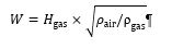
2.66. "Wobbe index (lower Wl; or upper Wu)" means the ratio of the corresponding calorific value of a gas per unit volume and the square root of its relative density under the same reference conditions:
2.67. "λ-shift factor (Sλ)" means an expression that describes the required flexibility of the engine management system regarding a change of the excess-air ratio λ if the engine is fuelled with a gas composition different from pure methane (see Appendix 5 to Annex 4 for the calculation of Sλ).
3. Application for approval
3.1. Application for type approval of an engine system or engine family as a separate technical unit
3.1.1. The manufacturer or his authorized representative shall submit to the Type Approval Authority an application for type approval of an engine system or engine family as a separate technical unit.
3.1.2. The application referred to in paragraph 3.1.1. shall be drawn up in accordance with the model of the information document set out in Annex 1. For that purpose Part 1 of Annex 1 shall apply.
3.1.3. Together with the application, the manufacturer shall provide a documentation package that fully explains any element of design which affects emissions, the emission control strategy of the engine system, the means by which the engine system controls the output variables which have a bearing upon emissions, whether that control is direct or indirect, anti-tampering measures and fully explains the warning and inducement system required by paragraphs 4. and 5. of Annex 11.
The documentation package shall be identified and dated by the approval authority and kept by that authority for at least 10 years after the approval is granted.
The documentation package shall consist of the following parts:
(a) The information set out in paragraph 5.1.4.;
(b) An AES documentation package, as described in Annex 2D to this Regulation in order for the approval authorities to be able to assess the proper use of AES.
At the request of the manufacturer, the approval authority shall conduct a preliminary assessment of the AES for new vehicle types. In that case, the manufacturer shall provide the draft AES documentation package to the approval authority between 2 and 12 months before the start of the type-approval process.
The approval authority shall make a preliminary assessment on the basis of the draft AES documentation package provided by the manufacturer. The approval authority shall make the preliminary assessment in accordance with the methodology described in Appendix 2 to Annex 10. The approval authority may deviate from that methodology in exceptional and duly justified cases.
The preliminary assessment of the AES for new vehicle types shall remain valid for the purposes of type approval for a period of 18 months. That period may be extended by a further 12 months if the manufacturer provides the approval authority with proof that no new technologies have become available on the market that would change the preliminary assessment of the AES.
3.1.4. In addition to the information referred to in paragraph 3.1.3., the manufacturer shall submit the following information:
(a) In the case of positive-ignition engines, a declaration by the manufacturer of the minimum percentage of misfires out of a total number of firing events that either would result in emissions exceeding the limits set out in Annex 9A if that percentage of misfire had been present from the start of the emission test as set out in Annex 4 or could lead to an exhaust catalyst, or catalysts, overheating prior to causing irreversible damage;
(b) A description of the provisions taken to prevent tampering with and modification of the emission control computer(s), including the facility for updating using a manufacturer-approved programme or calibration;
(c) Documentation of the OBD system, in accordance with the requirements set out in paragraph 8. of Annex 9B;
(d) OBD related information for the purpose of access to OBD, in accordance with the requirements of Annex 14 of this Regulation;
(e) A Statement of off-cycle emission compliance, with the requirements of paragraph 5.1.3. and paragraph 10. of Annex 10;
(f) A Statement of OBD in-use performance compliance, with the requirements of Appendix 2 to Annex 9A;
(g) The initial plan for in-service testing according to paragraph 2.4. of Annex 8;
(h) Where appropriate, copies of other type approvals with the relevant data to enable extension of approvals and establishment of deterioration factors;
(i) Where appropriate, the documentation packages required by this Regulation for the correct installation of the engine type-approved as separate technical unit
3.1.5. The manufacturer shall submit to the technical service responsible for the type approval tests an engine or, as appropriate, a parent engine representative of the type to be approved.
3.1.6. Changes to the make of a system, component or separate technical unit that occur after a type approval shall not automatically invalidate a type approval, unless its original characteristics or technical parameters are changed in such a way that the functionality of the engine or pollution control system is affected.
3.2. Application for type approval of a vehicle with an approved engine system with regard to emissions
3.2.1. The manufacturer or his authorized representative shall submit to the Type Approval Authority an application for type approval of a vehicle with an approved engine system with regard to emissions.
3.2.2. The application referred to in paragraph 3.2.1. shall be drawn up in accordance with the model of the information document set out in Part 2 of Annex 1. This application shall be accompanied by a copy of the type approval certificate for the engine system or engine family as a separate technical unit.
3.2.3. The manufacturer shall provide a documentation package that fully explains the elements of the warning and inducement system that is on board of the vehicle and required by Annex 11. This documentation package shall be provided in accordance with paragraph 3.1.3.
3.2.4. In addition to the information referred to in paragraph 3.2.3., the manufacturer shall submit the following information:
(a) A description of the measures taken to prevent tampering with and modification of the vehicle control units covered by this Regulation, including the facility for updating using a manufacturer-approved programme or calibration;
(b) A description of the OBD components on board of the vehicle, in accordance with the requirements of paragraph 8. of Annex 9B;
(c) Information related to the OBD components on board of the vehicle for the purpose of access to OBD;
(d) Where appropriate, copies of other type approvals with the relevant data to enable extension of approvals.
3.2.5. Changes to the make of a system, component or separate technical unit that occur after a type approval shall not automatically invalidate a type approval, unless its original characteristics or technical parameters are changed in such a way that the functionality of the engine or pollution control system is affected.
3.3. Application for type approval of a vehicle with regard to emissions
3.3.1. The manufacturer or his authorized representative shall submit to the Type Approval Authority an application for type approval of a vehicle with regard to emissions.
3.3.2. The application referred to in paragraph 3.3.1. shall be drawn up in accordance with the model of the information document set out in Annex 1. For that purpose Part 1 and Part 2 of that Annex shall apply.
3.3.3. The manufacturer shall provide a documentation package that fully explains any element of design which affects emissions, the emission control strategy of the engine system, the means by which the engine system controls the output variables which have a bearing upon emissions, whether that control is direct or indirect, and fully explains the warning and inducement system required by Annex 11. This documentation package shall be provided in accordance with paragraph 3.1.3.
3.3.4. In addition to the information referred to in paragraph 3.3.3., the manufacturer shall submit the information required by paragraph 3.1.4. (a) to (h) and paragraph 3.2.4. (a) to (d).
3.3.5. The manufacturer shall submit to the technical service responsible for the type approval tests an engine representative of the type to be approved.
3.3.6. Changes to the make of a system, component or separate technical unit that occur after a type approval shall not automatically invalidate a type approval, unless its original characteristics or technical parameters are changed in such a way that the functionality of the engine or pollution control system is affected.
3.4. Application for type approval of a type of replacement pollution control device as a separate technical unit
3.4.1. The manufacturer shall submit to the Type Approval Authority an application for type approval of a type of replacement pollution control device as a separate technical unit.
3.4.2. The application shall be drawn up in accordance with the model of the information document set out in Appendix 1 to Annex 13.
3.4.3. The manufacturer shall submit a Statement of compliance with the requirements on access to OBD information.
3.4.4. The manufacturer shall submit to the technical service responsible for the type approval test the following:
(a) An engine system or engine systems of a type approved in accordance with this Regulation equipped with a new original equipment pollution control device;
(b) One sample of the type of the replacement pollution control device;
(c) An additional sample of the type of the replacement pollution control device, in the case of a replacement pollution control device intended to be fitted to a vehicle equipped with an OBD system.
3.4.5. For the purposes of point (a) of paragraph 3.4.4., the test engines shall be selected by the applicant with the agreement of the Type Approval Authority.
The test conditions shall comply with the requirements set out in paragraph 6. of Annex 4.
The test engines shall respect the following requirements:
(a) They shall have no emission control system defects;
(b) Any malfunctioning or excessively worn emission-related original part shall be repaired or replaced;
(c) They shall be tuned properly and set to the manufacturer's specification prior to emission testing.
3.4.6. For the purposes of points (b) and (c) of paragraph 3.4.4., the sample shall be clearly and indelibly marked with the applicant's trade name or mark and its commercial designation.
3.4.7. For the purposes of point (c) of paragraph 3.4.4., the sample shall be a qualified deteriorated component.
4. Approval
4.1. In order to receive a type approval of an engine system or engine family as a separate technical unit, type approval of a vehicle with an approved engine system with regard to emissions, or a type approval of a vehicle with regard to emissions, the manufacturer shall, in accordance with the provisions of this Regulation demonstrate that the vehicles or engine systems are subject to the tests and comply with the requirements set out in paragraph 5. and Annexes 4, 6, 7, 9A, 9B, 9C, 10, 11, and 12. The manufacturer shall also ensure compliance with the specifications of reference fuels set out in Annex 5.
In order to receive type approval of a vehicle with an approved engine system with regard to emissions or a type approval of a vehicle with regard to emissions the manufacturer shall ensure compliance with the installation requirements set out in paragraph 6.
4.2. In order to receive an extension of the type approval of a vehicle with regard to emissions type-approved under this Regulation with a reference mass exceeding 2,380 kg but not exceeding 2,610kg the manufacturer shall meet the requirements set out in Appendix 1 to Annex 12.
4.3. In order to receive a type-approval of a dual-fuel engine or engine family as a separate technical unit, type-approval of a dual-fuel vehicle with an approved dual-fuel engine with regard to emissions, or a type-approval of a dual-fuel vehicle with regard to emissions, the manufacturer shall, in addition to the requirements of paragraph 4.1. demonstrate that the dual-fuel vehicles or engine are subject to the tests and comply with the requirements set out in Annex 15.
4.4. Reserved
4.5. In order to receive a type approval of an engine system or engine family as a separate technical unit or a type approval of a vehicle with regard to emissions, the manufacturer shall ensure compliance with the requirements on fuel range for a universal fuel approval or in case of a positive ignition engine fuelled with natural gas and LPG a restricted fuel range approval as specified in paragraph 4.6.
4.5.1. Tables summarizing the requirements for approval of NG-Fuelled engines, LPG-Fuelled engines and dual-fuelled engines are provided in Appendix 4.
4.6. Requirements on universal fuel range type approval
A universal fuel range approval shall be granted subject to the requirements specified in paragraphs 4.6.1. to 4.6.6.1.
4.6.1. The parent engine shall meet the requirements of this Regulation on the appropriate reference fuels specified in Annex 5. Specific requirements shall apply to engines fuelled with natural gas/biomethane (including dual-fuel engines), as laid down in paragraph 4.6.3.
4.6.2. If the manufacturer permits the engine family to run on market fuels that do not comply neither with the reference fuels included in Annex 5 nor CEN standard EN 228 (in the case of unleaded petrol) or CEN standard EN 590 (in the case of diesel), such as running on FAME B100 (CEN standard EN14214), FAME diesel blends B20/B30 (CEN standard EN 16709), paraffinic fuel (CEN standard EN 15940) or others the manufacturer shall, in addition to the requirements in paragraph 4.6.1. comply with the following requirements:
(a) Declare the fuels the engine family is capable to run on in paragraph 3.2.2.2.1. of the Information Document as set out in Part 1 of Annex 1, either by reference to an official standard or to a production specification of a brand specific market fuel not meeting any official standard such as those mentioned in paragraph 4.6.2. The manufacturer shall also declare that the functionality of the OBD system is not affected by the use of the declared fuel;
(b) Determine the power correction factor for each fuel declared according to paragraph 9.4.2.8. if applicable according to the provisions specified in paragraph 9.4.2.7. Declare the factor for each fuel in 3.2.2.2.2. of the information document as set out in Part 1 of Annex 1, if applicable;
(c) Demonstrate that the parent engine meets the requirements specified in Annex 4 and in Appendix 1 of Annex 10 to this Regulation on the fuels declared; the approval authority may request that the demonstration requirements be further extended to those laid down in Annex 7 and Annex 9A;
(d) Be liable to meet the requirements of in-service conformity specified in Annex 8 on the fuels declared, including any blend between the declared fuels and the relevant market fuels and standards.
At the request of the manufacturer, the requirements set out in this paragraph shall be applied to fuels used for military purposes.
For the purposes of subparagraph 4.6.2.(a) where the emission tests are performed for demonstrating compliance with the requirements of this Regulation, a fuel analysis report of the test fuel shall be attached to the test report and shall comprise at least the parameters specified in the official specification of the fuel manufacturer.
4.6.3. In the case of natural gas/biomethane fuelled engines, including dual-fuel engines, the manufacturer shall demonstrate the parent engines capability to adapt to any natural gas/biomethane composition that may occur across the market. This demonstration shall be carried out according to this paragraph and, in case of dual-fuel engines, also according to the additional provisions regarding the fuel adaptation procedure set out in paragraph 6.4. of Annex 15 to this Regulation.
4.6.3.1. In the case of compressed natural gas/biomethane (CNG) there are generally two types of fuel, high calorific fuel (H-gas) and low calorific fuel (L-gas), but with a significant spread within both ranges; they differ significantly in their energy content expressed by the Wobbe Index and in their λ-shift factor (Sλ). Natural gases with a λ-shift factor between 0.89 and 1.08 (0.89 ≤ Sλ ≤ 1.08) are considered to belong to H-range, while natural gases with a λ-shift factor between 1.08 and 1.19 (1.08 ≤ Sλ ≤ 1.19) are considered to belong to L-range. The composition of the reference fuels reflects the extreme variations of Sλ.
The parent engine shall meet the requirements of this Regulation on the reference fuels GR (fuel 1) and G25 (fuel 2), as specified in Annex 5, without any manual readjustment to the engine fuelling system between the two tests (self-adaptation is required). One adaptation run over one WHTC hot cycle without measurement is permitted after the change of the fuel. After the adaptation run the engine shall be cooled down in accordance with
paragraph 7.6.1. of Annex 4.
4.6.3.1.1. At the manufacturer's request the engine may be tested on a third fuel (fuel 3) if the λ-shift factor (Sλ) lies between 0.89 (that is the lower range of GR) and 1.19 (that is the upper range of G25), for example when fuel 3 is a market fuel. The results of this test may be used as a basis for the evaluation of the conformity of the production.
4.6.3.2. In the case of liquefied natural gas/liquefied biomethane (LNG) the parent engine shall meet the requirements of this Regulation on the reference fuels GR (fuel 1) and G20 (fuel 2), as specified in Annex 5, without any manual readjustment to the engine fuelling system between the two tests (self-adaptation is required). One adaptation run over one WHTC hot cycle without measurement is permitted after the change of the fuel. After the adaptation run, the engine shall be cooled down in accordance with paragraph 7.6.1. of Annex 4.
4.6.4. In the case of an engine fuelled with compressed natural gas/biomethane (CNG) which is self-adaptive for the range of H-gases on the one hand and the range of L-gases on the other hand, and which switches between the H-range and the L-range by means of a switch, the parent engine shall be tested on the relevant reference fuel as specified in Annex 5 for each range, at each position of the switch. The fuels are GR (fuel 1) and G23 (fuel 3) for the H-range of gases and G25 (fuel 2) and G23 (fuel 3) for the L-range of gases. The parent engine shall meet the requirements of this Regulation at both positions of the switch without any readjustment to the fuelling between the two tests at each position of the switch. One adaptation run over one WHTC hot cycle without measurement is permitted after the change of the fuel. After the adaptation run the engine shall be cooled down in accordance with paragraph 7.6.1. of Annex 4.
4.6.4.1. At the manufacturer's request the engine may be tested on a third fuel instead of G23 (fuel 3) if the λ-shift factor (Sλ) lies between 0.89 (that is the lower range of GR) and 1.19 (that is the upper range of G25), for example when fuel 3 is a market fuel. The results of this test may be used as a basis for the evaluation of the conformity of the production.
4.6.5. In the case of natural gas/biomethane engines, the ratio of the emission results "r" shall be determined for each pollutant as follows:

or,

and,

4.6.6. In the case of LPG the manufacturer shall demonstrate the parent engines capability to adapt to any fuel composition that may occur across the market.
In the case of LPG there are variations in C3/C4 composition. These variations are reflected in the reference fuels. The parent engine shall meet the emission requirements on the reference fuels A and B as specified in Annex 5 without any readjustment to the fuelling between the two tests. One adaptation run over one WHTC hot cycle without measurement is permitted after the change of the fuel. After the adaptation run the engine shall be cooled down in accordance with paragraph 7.6.1. of Annex 4.
4.6.6.1. The ratio of emission results "r" shall be determined for each pollutant as follows:

4.7. Requirements on restricted fuel range type-approval in case of engines fuelled with natural gas/biomethane or LPG, including dual-fuel engines.
Restricted fuel range type approval shall be granted subject to the requirements specified in paragraphs 4.7.1. to 4.7.2.3. below.
4.7.1. Exhaust emissions type-approval of an engine running on CNG and laid out for operation on either the range of H-gases or on the range of L-gases.
4.7.1.1. The parent engine shall be tested on the relevant reference fuel, as specified in Annex 5, for the relevant range. The fuels are GR (fuel 1) and G23 (fuel 3) for the H-range of gases and G25 (fuel 2) and G23 (fuel 3) for the L-range of gases. The parent engine shall meet the requirements of this Regulation without any readjustment to the fuelling between the two tests. One adaptation run over one WHTC hot cycle without measurement is permitted after the change of the fuel. After the adaptation run the engine shall be cooled down in accordance with paragraph 7.6.1. of Annex 4.
4.7.1.2. At the manufacturer's request the engine may be tested on a third fuel instead of G23 (fuel 3) if the λ-shift factor (Sλ) lies between 0.89 (that is the lower range of GR) and 1.19 (that is the upper range of G25), for example when fuel 3 is a market fuel. The results of this test may be used as a basis for the evaluation of the conformity of the production.
4.7.1.3. The ratio of emission results "r" shall be determined for each pollutant as follows:

or,

and,

4.7.1.4. On delivery to the customer the engine shall bear a label as specified in paragraph 4.12.8. stating for which range of gases the engine is approved.
4.7.2. Exhaust emissions type approval of an engine running on natural gas or LPG and designed for operation on one specific fuel composition.
4.7.2.1. The parent engine shall meet the emission requirements on the reference fuels GR and G25 in the case of CNG, on the reference fuels GR and G20 in the case of LNG, or on the reference fuels A and B in the case of LPG, as specified in Annex 5 to this Regulation. Fine-tuning of the fuelling system is allowed between the tests. This fine-tuning will consist of a recalibration of the fuelling database, without any alteration to either the basic control strategy or the basic structure of the database. If necessary the exchange of parts that are directly related to the amount of fuel flow such as injector nozzles is allowed.
4.7.2.2. In the case of CNG, at the manufacturer's request, the engine may be tested on the reference fuels GR and G23, or on the reference fuels G25 and G23, in which case the type-approval is only valid for the H-range or the L-range of gases respectively.
4.7.2.3. On delivery to the customer the engine shall bear a label as specified in paragraph 4.12.8. below stating for which fuel range composition the engine has been calibrated.
4.8. Requirements on fuel-specific type-approval in the case of engines fuelled with liquefied natural gas/liquefied biomethane (LNG)
In case of liquefied natural gas/liquefied biomethane, a fuel specific type-approval may be granted subject to the requirements specified in paragraphs 4.8.1. to 4.8.2.
4.8.1. Conditions for applying for a fuel-specific type approval in the case of engines fuelled with liquefied natural gas/liquefied biomethane (LNG).
4.8.1.1. The manufacturer can only apply for a fuel specific type-approval in the case of the engine being calibrated for a specific LNG gas composition resulting in a -shift factor not differing by more than 3 per cent from the -shift factor of the G20 fuel specified in Annex 5, and the ethane content of which does not exceed 1.5 per cent.
4.8.1.2. In all other cases the manufacturer shall apply for a universal fuel type approval according to the specifications of paragraph 4.6.3.2.
4.8.2. Specific test requirements in the case of a fuel-specific type approval (LNG).
4.8.2.1. In the case of a dual-fuel engine family where the engines are calibrated for a specific LNG gas composition2 resulting in a -shift factor not differing by more than 3 per cent from the -shift factor of the G20 fuel specified in Annex 5, and the ethane content of which does not exceed 1.5 per cent, the parent engine shall only be tested on the G20 reference gas fuel, as specified in Annex
4.9. Exhaust emissions type approval of a member of a family
4.9.1. With the exception of the case mentioned in paragraph 4.8.2., the type approval of a parent engine shall be extended to all family members, without further testing, for any fuel composition within the range for which the parent engine has been approved (in the case of engines described in paragraph 4.7.2.) or the same range of fuels (in the case of engines described in either paragraph 4.6. or 4.7.) for which the parent engine has been type-approved.
4.9.2. If the technical service determines that, with regard to the selected parent engine the submitted application does not fully represent the engine family defined in Part 1 of Annex 1, an alternative and if necessary an additional reference test engine may be selected by the technical service and tested.
4.10. Requirements for approval regarding the on-board diagnostic systems
4.10.1. Manufacturers shall ensure that all engine systems and vehicles are equipped with an OBD system.
4.10.2. The OBD system shall be designed, constructed and installed on a vehicle in accordance with Annex 9A, so as to enable it to identify, record, and communicate the types of deterioration or malfunction specified in that Annex over the entire life of the vehicle.
4.10.3. The manufacturer shall ensure that the OBD system complies with the requirements set out in Annex 9A, including the OBD in-use performance requirements, under all normal and reasonably foreseeable driving conditions, including the conditions of normal use specified in Annex 9B.
4.10.4. When tested with a qualified deteriorated component, the OBD system malfunction indicator shall be activated in accordance with Annex 9B. The OBD system malfunction indicator may also be activated at levels of emissions below the OBD thresholds limits specified in Annex 9A.
4.10.5. The manufacturer shall ensure that the provisions for in-use performance of an OBD engine family laid down in Annex 9A are followed.
4.10.6. The OBD in-use performance related data shall be stored and made available without any encryption through the standard OBD communication protocol by the OBD system in accordance with the provisions of Annex 9A.
4.10.7. If the manufacturer chooses, until the date specified in paragraph 13.2.3. for new type approvals, OBD systems may comply with alternative provisions as specified in Annex 9A and referring to this paragraph.
4.10.8. If the manufacturer chooses, until the date specified in paragraph 13.2.3. for new type approvals, he may use alternative provisions for the monitoring of the Diesel Particulate Filter (DPF) as set out in paragraph 2.3.2.2. of Annex 9A.
4.11. Requirements for approval regarding replacement pollution control devices
4.11.1. The manufacturer shall ensure that replacement pollution control devices intended to be fitted to type-approved engine systems or vehicles covered by this Regulation are type-approved, as separate technical units in accordance with the requirements of paragraphs 4.11.2. to 4.11.5.
Catalytic converters, deNOx devices and particulate filters shall be considered to be pollution control devices for the purposes of this Regulation.
4.11.2. Original replacement pollution control devices, which fall within the type covered by paragraph 3.2.12. of Part 1 of Annex 1 and are intended for fitment to a vehicle to which the relevant type approval document refers, do not need to comply with all provisions of Annex 13 provided that they fulfil the requirements of paragraphs 2.1., 2.2. and 2.3. of that annex.
4.11.3. The manufacturer shall ensure that the original pollution control device carries identification markings.
4.11.4. The identification markings referred to in paragraph 4.11.3. shall comprise the following:
(a) The vehicle or engine manufacturer's name or trade mark;
(b) The make and identifying part number of the original pollution control device as recorded in the information referred to in paragraph 3.2.12.2. of Part 1 of Annex 1.
4.11.5. Replacement pollution control devices shall be type approved according to the specific testing requirements specified in Annex 13 of this Regulation.
4.12. Approval marks and labelling for engine systems and vehicles
4.12.1. An approval number shall be assigned to each type approved. Its first two digits (at present 07, corresponding to 07 series of amendments) shall indicate the series of amendments incorporating the most recent major technical amendments made to the Regulation at the time of issue of the approval. The same Contracting Party shall not assign the same number to another engine type or vehicle type.
4.12.2. Notice of approval or of extension or of refusal of approval or production definitively discontinued of an engine type or vehicle type pursuant to this Regulation shall be communicated to the Parties to the 1958 Agreement which apply this Regulation, by means of a form conforming to the model in Annexes 2A, 2B or 2C, as applicable, to this Regulation. Values measured during the type test shall also be shown.
4.12.3. There shall be affixed, conspicuously and in a readily accessible place to every engine conforming to an engine type-approved under this Regulation, or to every vehicle conforming to a vehicle type-approved under this Regulation, an international approval mark consisting of:
4.12.3.1. A circle surrounding the letter "E" followed by the distinguishing number of the country which has granted approval;
4.12.3.2. The number of this Regulation, followed by the letter "R", a dash and the approval number to the right of the circle prescribed in paragraph 4.12.3.1.
4.12.3.3. The approval mark shall also contain a dash and an additional character after the approval number, the purpose of which is to distinguish the stage for which the approval has been granted according paragraph 13.2. and communicated in Table 1 in Annex 3.
4.12.3.3.1. For diesel fuelled CI engines the approval mark shall contain the letter "D" after the national symbol, the purpose of which is to distinguish the type of engine for which the approval has been granted.
4.12.3.3.2. For ethanol (ED95) fuelled CI engines the approval mark shall contain the letters "ED" after the national symbol, the purpose of which is to distinguish the type of engine for which the approval has been granted.
4.12.3.3.3. For ethanol (E85) fuelled PI engines the approval mark shall contain "E85" after the national symbol, the purpose of which is to distinguish the type of engine for which the approval has been granted.
4.12.3.3.4. For petrol fuelled PI engines the approval mark shall contain the letter "P" after the national symbol, the purpose of which is to distinguish the type of engine for which the approval has been granted.
4.12.3.3.5. For LPG fuelled PI engines the approval mark shall contain the letter "Q" after the national symbol, the purpose of which is to distinguish the type of engine for which the approval has been granted.
4.12.3.3.6. For natural gas/biomethane fuelled engines the approval mark shall contain a letter/s after the national symbol, the purpose of which is to distinguish which range of gases the approval has been granted. This letter/s will be as follows:
(a) H in case of the engine being approved and calibrated for the H‑range of gases;
(b) L in case of the engine being approved and calibrated for the L‑range of gases;
(c) HL in case of the engine being approved and calibrated for both the H‑range and L‑range of gases;
(d) Ht in case of the engine being approved and calibrated for a specific gas composition in the H-range of gases and transformable to another specific gas in the H-range of gases by fine tuning of the engine fuelling;
(e) Lt in case of the engine being approved and calibrated for a specific gas composition in the L-range of gases and transformable to another specific gas in the L-range of gases after fine tuning of the engine fuelling;
(f) HLt in the case of the engine being approved and calibrated for a specific gas composition in either the H-range or the L-range of gases and transformable to another specific gas in either the H‑range or the L-range of gases by fine tuning of the engine fueling;
(g) CNGfr in all other cases where the engine is fuelled with CNG/biomethane and designed for operation on one restricted gas fuel range composition;
(h) LNGfr in the cases where the engine is fuelled with LNG and designed for operation on one restricted gas fuel range composition;
(i) LPGfr in the cases where the engine is fuelled with LPG and designed for operation on one restricted gas fuel range composition;
(j) LNG20 in case of the engine being approved and calibrated for a specific liquefied natural gas/liquefied biomethane composition resulting in a λ-shift factor not differing by more than 3 per cent the λ-shift factor of the G20 gas specified in Annex 5 to this Regulation, and the ethane content of which does not exceed 1.5 per cent;
(k) LNG in case of the engine being approved and calibrated for any other liquefied natural gas/liquefied biomethane composition.
4.12.3.3.7. For dual-fuel engines the approval mark shall contain a series of digits after the national symbol, the purpose of which is to distinguish for which dual-fuel engine type and with which range of gases the approval has been granted.
This series of digits will be constituted of two digits identifying the dual-fuel engine type as defined in Annex 15 followed by the letter(s) specified in paragraphs 4.12.3.3.1. to 4.12.3.3.6. corresponding to the natural gas/biomethane composition used by the engine.
The two digits identifying the dual-fuel engines types according to the definitions of Annex 15 are the following:
(a) 1A for dual-fuel engines of Type 1A;
(b) 1B for dual-fuel engines of Type 1B;
(c) 2A for dual-fuel engines of Type 2A;
(d) 2B for dual-fuel engines of Type 2B;
(e) 3B for dual-fuel engines of Type 3B."
4.12.3.4. In addition to the marking on the engine, the approval mark may also be retrievable via the instrument cluster. It shall then be readily available for inspection and the access instructions included in the user manual of the vehicle.
4.12.4. If the vehicle or engine conforms to an approved type under one or more other Regulations annexed to the Agreement, in the country which has granted approval under this Regulation, the symbol prescribed in paragraph 4.12.3.1. does not need to be repeated. In such a case, the Regulation and approval numbers and the additional symbols of all the Regulations under which approval has been granted under this Regulation shall be placed in vertical columns to the right of the symbol prescribed in paragraph 4.12.3.1.
4.12.5. The approval mark shall be placed close to or on the data plate affixed by the manufacturer to the approved type.
4.12.6. Annex 3 to this Regulation gives examples of arrangements of approval marks.
4.12.7. The engine approved as a technical unit shall bear, in addition to the approved mark:
4.12.7.1. The trademark or trade name of the manufacturer of the engine;
4.12.7.2. The manufacturer's commercial description of the engine
4.12.8. Labels for natural gas/biomethane and LPG fuelled engines
In the case of natural gas and LPG fuelled engines with a restricted fuel range type-approval, the following labels are applicable:
4.12.8.1. Content
The following information shall be given:
In the case of paragraph 4.7.1.4., the label shall state "ONLY FOR USE WITH NATURAL GAS RANGE H". If applicable, "H" is replaced by "L".
In the case of paragraph 4.7.2.3., the label shall state "ONLY FOR USE WITH NATURAL GAS SPECIFICATION ..." or "ONLY FOR USE WITH LIQUEFIED PETROLEUM GAS SPECIFICATION ...", as applicable. All the information in the relevant table(s) in Annex 5 shall be given with the individual constituents and limits specified by the engine manufacturer.
The letters and figures shall be at least 4 mm in height.
Note: If lack of space prevents such labelling, a simplified code may be used. In this event, explanatory notes containing all the above information shall be easily accessible to any person filling the fuel tank or performing maintenance or repair on the engine and its accessories, as well as to the authorities concerned. The site and content of these explanatory notes will be determined by agreement between the manufacturer and the Type Approval Authority.
4.12.8.2. Properties
Labels shall be durable for the useful life of the engine. Labels shall be clearly legible and their letters and figures shall be indelible. Additionally, labels shall be attached in such a manner that their fixing is durable for the useful life of the engine, and the labels cannot be removed without destroying or defacing them.
4.12.8.3. Placing
Labels shall be secured to an engine part necessary for normal engine operation and not normally requiring replacement during engine life. Additionally, these labels shall be located so as to be readily visible after the engine has been completed with all the auxiliaries necessary for engine operation.
4.13. In case of an application for approval for a vehicle type in respect of its engine, the marking specified in paragraph 4.12.8. shall also be placed close to fuel filling aperture.
4.14. In case of an application for approval for a vehicle type with an approved engine, the marking specified in paragraph 4.12.8. shall also be placed close to the fuel filling aperture.
5. Requirements and tests
5.1. General
5.1.1. Manufacturers shall equip vehicles and engines so that the components likely to affect emissions are designed, constructed and assembled so as to enable the vehicle or engine, in normal use, to comply with this Regulation and its implementing measures.
5.1.2. The manufacturer shall take technical measures so as to ensure that the tailpipe emissions are effectively limited, in accordance with this Regulation, throughout the normal life of the vehicle and under normal conditions of use.
5.1.2.1. Those measures referred to in paragraph 5.1.2. shall include ensuring that the security of hoses, joints and connections, used within the emission control systems, are constructed so as to conform to the original design intent.
5.1.2.2. The manufacturer shall ensure that the emissions test results comply with the applicable limit value under the test conditions specified in this Regulation.
5.1.2.3. Any engine system and any element of design liable to affect the emission of gaseous and particulate pollutants shall be designed, constructed, assembled and installed so as to enable the engine, in normal use, to comply with the provisions of this Regulation. The manufacturer shall also ensure compliance with off-cycle requirements set out in paragraph 5.1.3. and Annex 10.
5.1.2.4. The use of defeat strategies that reduce the effectiveness of emission control equipment shall be prohibited.
5.1.2.5. In order to receive a type approval in the case of a petrol or E85 fuelled engine, the manufacturer shall ensure that the specific requirements for inlets to fuel tanks for petrol and E85 fuelled vehicles laid down in paragraph 6.3. are fulfilled.
5.1.3. Requirements to limit off-cycle emissions
5.1.3.1. When meeting the requirements of paragraph 5.1.2., the technical measures undertaken shall take the following into account:
(a) The general requirements, including the performance requirements and the prohibition of defeat strategies, as specified in Annex 10;
(b) The requirements to effectively limit the tailpipe emissions under the range of ambient conditions under which the vehicle may be expected to operate, and under the range of operating conditions that may be encountered;
(c) The requirements with respect to off-cycle laboratory testing at type approval;
(d) The requirements with respect to the PEMS demonstration test at type approval and any additional requirements with respect to off-cycle in-use vehicle testing, as provided for in this Regulation;
(e) The requirement for the manufacturer to provide a statement of compliance with the requirements limiting off-cycle emissions.
5.1.3.2. The manufacturer shall fulfil the specific requirements, together with the associated test procedures, set out in Annex 10.
5.1.4. Documentation requirements
5.1.4.1. The documentation package required by paragraph 3. of this Regulation enabling the Type Approval Authority to evaluate the emission control strategies and the systems on-board the vehicle and engine to ensure the correct operation of NOx control measures, as well as the documentation packages required in Annex 10 (off-cycle emissions), Annexes 9A and 9B (OBD) and Annex 15 to this Regulation (dual-fuel engines), shall include the following information:
(a) A full description of the inducement system required by Annex 11, including the associated monitoring strategies;
(b) The description of the anti-tampering measures considered in paragraph 3.1.4.(b) and in paragraph 3.2.4.(a).
5.1.4.2. The formal documentation package may be brief, provided that it exhibits evidence that all outputs permitted by a matrix obtained from the range of control of the individual unit inputs have been identified. The documentation shall describe the functional operation of the inducement system required by Annex 11, including the parameters necessary for retrieving the information associated with that system. This material shall be retained by the Type Approval Authority.
5.1.4.3. The extended documentation package shall include:
(a) Information on the operation of all AES and BES, including a description of the parameters that are modified by any AES and the boundary conditions under which the AES operate, and indication of which AES and BES are likely to be active under the conditions of the test procedures set out in Annex 10 to this Regulation;
(b) A description of the fuel system control logic, timing strategies and switch points during all modes of operation;
(c) A full description of the inducement system required in Annex 11 to this Regulation, including the associated monitoring strategies;
(d) The description of the anti-tampering measures considered in paragraph 3.1.4. (b) and in paragraph 3.2.4. (a) of this Regulation.
5.1.4.4. The extended documentation package shall remain strictly confidential. It may be kept by the Type Approval Authority, or, at the discretion of the Type Approval Authority, may be retained by the manufacturer. In the case the manufacturer retains the documentation package, that package shall be identified and dated by the Type Approval Authority once reviewed and approved. It shall be made open for inspection by the Type Approval Authority at the time of approval or at any time during the validity of the approval.
5.1.5. Provisions for electronic system security
5.1.5.1. The general requirements, including the specific requirements for electronic system security, shall be those set out in paragraph 4. of Annex 9B of this Regulation and those described in paragraph 2. of Annex 9A.
5.2. Specifications concerning the emission of gaseous and particulate pollutants
5.2.1. In undertaking the tests set out in Annex 4 the gaseous and particulate matter emissions shall not exceed the amounts shown in Table 1.
5.2.2. For positive ignition engines subject to the test set out in Annex 6, the maximum permissible carbon monoxide content in the exhaust gases at normal engine idling speed shall be that stated by the vehicle manufacturer. However, the maximum carbon monoxide content shall not exceed 0.3 per cent vol.
At high idle speed, the carbon monoxide content by volume of the exhaust gases shall not exceed 0.2 per cent vol., with the engine speed being at least 2,000 min-1 and Lambda being 1 ± 0.03 or in accordance with the specifications of the manufacturer.
5.2.3. In the case of a closed crankcase, manufacturers shall ensure that for the tests set out in paragraphs 6.10. and 6.11. of Annex 4, the engine’s ventilation system does not permit the emission of any crankcase gases into the atmosphere. If the crankcase is of an open type, the emissions shall be measured and added to the tailpipe emissions, following the provisions set out in paragraph 6.10. of Annex 4.
5.2.4. For the dilute testing of positive ignition engines by using an exhaust dilution system, it is permitted to use analyser systems that meet the general requirements and calibration procedures of UN Regulation No. 83 or UN Regulation No. 154. In this case, the provisions of paragraph 9. and Appendix 2 to Annex 4 to this Regulation shall not apply.
However, the test procedures in paragraph 7. of Annex 4 to this Regulation and the emission calculations provided in paragraph 8. of Annex 4 shall apply.
5.3. Emission limits
Table 1 provides the emissions limits that apply to this Regulation.
Table 1
Emission limits
| Limit values |
CO (mg/kWh) | THC (mg/kWh) | NMHC (mg/kWh) | CH4 (mg/kWh) | NOX* (mg/kWh) | NH3 (ppm) | PM mass (mg/kWh) | PM number (#/kWh) |
WHSC (CI) | 1,500 | 130 | | | 400 | 10 | 10 | 8.0 x 10¹¹ |
WHTC (CI) | 4,000 | 160 | | | 460 | 10 | 10 | 6.0 x 10¹¹** |
WHTC (PI) | 4,000 | | 160 | 500 | 460 | 10 | 10 | 6.0 x 10¹¹** |
Notes: PI Positive Ignition CI Compression Ignition * The admissible level of NO2 component in the NOX limit value may be defined at a later stage. ** The limit shall apply as from the dates set out in row B of Table 1 in Appendix 9 to Annex 1 to this Regulation. |
5.4. Durability and deterioration factors
The manufacturer shall determine deterioration factors that will be used to demonstrate that the gaseous and particulate emissions of an engine family or engine- after-treatment system family remain in conformity with the emission limits set out in paragraph 5.3. over the normal useful life periods set out below.
The procedures for demonstrating the compliance of an engine system or engine-after-treatment system family over the normal useful life are set out in Annex 7.
The mileage and period of time by reference to which the tests for durability of pollution control devices undertaken for type approval and testing of conformity of in-service vehicles or engines are to be carried out shall be the following:
(a) 160,000 km or five years, whichever is the sooner, in the case of engines fitted to vehicles of category M1, N1 and M2;
(b) 300,000 km or six years, whichever is the sooner, in the case of engines fitted to vehicles of category N2, N3 with a maximum technically permissible mass not exceeding 16 tonnes and M3 Class I, Class II and Class A, and Class B with a maximum technically permissible mass not exceeding 7.5 tonnes;
(c) 700,000 km or seven years, whichever is the sooner, in the case of engines fitted to vehicles of category N3 with a maximum technically permissible mass exceeding 16 tonnes and M3, Class III and Class B with a maximum technically permissible mass exceeding 7.5 tonnes.
5.5. Requirements to ensure correct operation of NOx control measures
5.5.1. When applying for type approval, manufacturers shall present to the Type Approval Authority information showing that the NOx system retains its emission control function during all conditions regularly pertaining in the region (e.g. European Union), especially at low temperatures.
In addition, manufacturers shall provide the Type Approval Authority with information on the operating strategy of any exhaust gas recirculation system (EGR), including its functioning at low ambient temperatures.
This information shall also include a description of any effects on emissions of operating the system under low ambient temperatures.
Information on the tests and procedures for fulfilling these requirements is provided in Annex 11.
6. Installation on the vehicle
6.1. The engine installation on the vehicle shall be performed in such a way as to ensure that the type approval requirements are met. The following characteristics in respect to the type approval of the engine shall be taken into consideration:
6.1.1. Intake depression shall not exceed that declared for the engine type approval in Part 1 of Annex 1;
6.1.2. Exhaust back pressure shall not exceed that declared for the engine type approval in Part 1 of Annex 1;
6.1.3. Power absorbed by the auxiliaries needed for operating the engine shall not exceed that declared for the engine type approval in Part 1 of Annex 1;
6.1.4. The characteristics of the exhaust after-treatment system shall be in accordance with those declared for the engine type approval in Part 1 of Annex 1.
6.2. Installation of a type-approved engine on a vehicle
6.2.1. The installation of an engine type-approved as a separate technical unit on a vehicle shall, in addition, comply with the following requirements:
(a) As regard to the compliance of the OBD system, the installation shall, according to Appendix 1 to Annex 9B to this Regulation, meet the manufacturer's installation requirements as specified in Part 1 of Annex 1;
(b) As regard to the compliance of the system ensuring the correct operation of NOx control measures, the installation shall, according to Appendix 4 to Annex 11 to this Regulation, meet the manufacturer's installation requirements as specified in Part 1 of Annex 1 to this Regulation;
(c) The installation of a dual-fuel engine type-approved as a separate technical unit on a vehicle shall, in addition, meet the specific installation requirements and the manufacturer's installation requirements set out in Annex 15 to this Regulation.
6.3. Inlet to fuel tanks in the case of a petrol or E85 fuelled engine
6.3.1. The inlet orifice of the petrol or E85 tank shall be designed so it prevents the tank from being filled from a fuel pump delivery nozzle that has an external diameter of 23.6 mm or greater.
6.3.2. Paragraph 6.3.1. shall not apply to a vehicle for which both of the following conditions are satisfied:
(a) The vehicle is designed and constructed so that no device designed to control the emission of gaseous pollutants is adversely affected by leaded petrol;
(b) The vehicle is conspicuously, legibly and indelibly marked with the symbol for unleaded petrol specified in ISO 2575:2004 in a position immediately visible to a person filling the fuel tank. Additional marking are permitted.
6.3.3. Provision shall be made to prevent excess evaporative emissions and fuel spillage caused by a missing fuel filler cap. This may be achieved by using one of the following:
(a) An automatically opening and closing, non-removable fuel filler cap;
(b) Design features which avoid excess evaporative emissions in the case of a missing fuel filler cap;
(c) Or in case of M1 or N1 vehicles, any other provision which has the same affect. Examples may include, but are not limited to, a tethered filler cap, a chained filler cap or one utilizing the same locking key for the filler cap as for the vehicle’s ignition. In this case the key shall be removable from the filler cap only in the locked condition.
7. Engine family
7.1. Parameters defining the engine family
The engine family, as determined by the engine manufacturer shall comply with paragraph 5.2. of Annex 4.
In case of a dual-fuel engine, the engine family shall also comply with the additional requirements of paragraph 3.1.1. of Annex 15.
7.2. Choice of the parent engine
The parent engine of the family shall be selected in accordance with the requirements set out in paragraph 5.2.4. of Annex 4.
7.3. Extension to include a new engine system into an engine-family
7.3.1. At the request of the manufacturer and upon approval of the Type Approval Authority, a new engine system may be included as a member of a certified engine family if the criteria specified in paragraph 7.1. are met.
7.3.2. If the elements of design of the parent engine system are representative of those of the new engine system according to paragraph 7.2. or, in the case of dual-fuel engines, to paragraph 3.1.2. of Annex 15, then the parent engine system shall remain unchanged and the manufacturer shall modify the information document specified in Annex 1.
7.3.3. If the new engine system contains elements of design that are not represented by the parent engine system according to paragraph 7.2. or, in the case of dual-fuel engines, to paragraph 3.1.2. of Annex 15, but itself would represent the whole family according to these paragraphs, then the new engine system shall become the new parent engine. In this case the new elements of design shall be demonstrated to comply with the provisions of this Regulation and the information document specified in Annex 1 shall be modified.
7.4. Parameters for defining an OBD-engine family
The OBD-engine family shall be determined by basic design parameters that shall be common to engine systems within the family, in accordance with paragraph 6.1. of Annex 9B.
8. Conformity of production
8.1. Every engine or vehicle bearing an approval mark as prescribed under this Regulation shall be so manufactured as to conform, with regard to the description as given in the approval form and its annexes, to the approved type. The conformity of production procedures shall comply with those set out in Appendix 2 to the 1958 Agreement (E/ECE/324//E/ECE/TRANS/505/Rev.2), with the following requirements set out in paragraphs 8.2. to 8.5.
8.1.1. Conformity of production shall be checked on the basis of the description in the type approval certificates set out in Annexes 2A, 2B and 2C, as applicable.
8.1.2. Conformity of production shall be assessed in accordance with the specific conditions laid down in this paragraph and the relevant statistical methods laid down in Appendices 1, 2 and 3.
8.2. General requirements
8.2.1. In applying Appendices 1, 2 or 3, the measured emission of the gaseous and particulate pollutants from engines subject to checking for conformity of production shall be adjusted by application of the appropriate deterioration factors (DF’s) for that engine as recorded in the Addendum to the type approval certificate granted in accordance with this Regulation.
8.2.2. The provisions set out in Appendix 2 to the 1958 Agreement (E/ECE/324//E/ECE/TRANS/505/Rev.2) shall be applicable where the approval authorities are not satisfied with the auditing procedure of the manufacturer.
8.2.3. All engines subject to tests shall be randomly taken from the series production.
8.3. Emissions of pollutants
8.3.1. If emissions of pollutants are to be measured and an engine type approval has had one or more extensions, the tests shall be carried out on the engines described in the information package relating to the relevant extension.
8.3.2. Conformity of the engine subjected to a pollutant test:
After submission of the engine to the authorities, the manufacturer may not carry out any adjustment to the engines selected.
8.3.2.1. Three engines shall be taken from the series production of the engines under consideration. Engines shall be subjected to testing on the WHTC and on the WHSC, if applicable, for the checking of the production conformity. The limit values shall be those set out in paragraph 5.3.
8.3.2.2. Where the Type Approval Authority is satisfied with the production standard deviation given by the manufacturer in accordance with Appendix 2 to the 1958 Agreement (E/ECE/324//E/ECE/TRANS/505/Rev.2), the tests shall be carried out according to Appendix 1.
Where the Type Approval Authority is not satisfied with the production standard deviation given by the manufacturer in accordance with Appendix 2 to the 1958 Agreement (E/ECE/324//E/ECE/TRANS/505/Rev.2), the tests shall be carried out according to Appendix 2.
At the manufacturer’s request, the tests may be carried out in accordance with Appendix 3.
8.3.2.3. On the basis of tests of the engine by sampling as set out in paragraph 8.3.2.2., the series production of the engines under consideration is regarded as conforming where a pass decision is reached for all the pollutants and as non-conforming where a fail decision is reached for one pollutant, in accordance with the test criteria applied in the appropriate Appendix.
When a pass decision has been reached for one pollutant, this decision may not be changed as a consequence of a result from any additional tests made in order to reach a decision for the other pollutants.
If a pass decision is not reached for all the pollutants and if no fail decision is reached for any pollutant, a test is carried out on another engine (see Figure 1).
If no decision is reached, the manufacturer may at any time decide to stop testing. In that case a fail decision is recorded.
Figure 1
Schematic of production conformity testing

8.3.3. The tests shall be carried out on newly manufactured engines.
8.3.3.1. At the request of the manufacturer, the tests may be carried out on engines which have been run-in, up to a maximum of 125 hours. In this case, the running-in procedure shall be conducted by the manufacturer who shall undertake not to make any adjustments to those engines.
8.3.3.2. When the manufacturer requests to conduct a running-in procedure in accordance with paragraph 8.3.3.1., it may be carried out on either of the following:
(a) All the engines that are tested;
(b) The first engine tested, with the determination of an evolution coefficient as follows:
(i) The pollutant emissions shall be measured both on the newly manufactured engine and before the maximum of 125 hours set in paragraph 8.3.3.1. on the first engine tested;
(ii) The evolution coefficient of the emissions between the two tests shall be calculated for each pollutant:
Emissions on second test/Emissions first test;
The evolution coefficient may have a value less than one.
The subsequent test engines shall not be subjected to the running-in procedure, but their emissions when newly manufactured shall be modified by the evolution coefficient.
In this case, the values to be taken shall be the following:
(a) For the first engine, the values from the second test;
(b) For the other engines, the values when newly manufactured multiplied by the evolution coefficient.
8.3.3.3. For diesel, ethanol (ED95), petrol, E85, LNG20, LNG and LPG fuelled, including dual-fuel, engines, all these tests may be conducted with the applicable market fuels. However, at the manufacturer’s request, the reference fuels described in Annex 5 to this Regulation may be used. This implies tests, as described in paragraph 4. of this Regulation.
8.3.3.4. For CNG engines, including dual-fuel engines, all these tests may be conducted with market fuel in the following way:
(a) For H marked engines with a market fuel within the H-range (0.89 ≤ Sλ ≤ 1.00);
(b) For L marked engines with a market fuel within the L-range
(1.00 ≤ Sλ ≤ 1.19);
(c) For HL marked engines with a market fuel within the extreme range of the λ-shift factor (0.89 ≤ Sλ ≤ 1.19).
However, at the manufacturer’s request, the reference fuels described in Annex 5 may be used. This implies tests as described paragraph 4.
8.3.3.5. Non-compliance of gas and dual-fuel engines
In the case of dispute caused by the non-compliance of gas fuelled engines, including dual-fuel engines, when using a market fuel, the tests shall be performed with each reference fuel on which the parent engine has been tested, and, at the request of the manufacturer, with the possible additional third fuel, as referred to in paragraphs 4.6.4.1. and 4.7.1.2. of this Regulation, on which the parent engine may have been tested.
When applicable, the result shall be converted by a calculation, applying the relevant factors "r", "ra" or "rb" as described in paragraphs 4.6.5., 4.6.6.1. and 4.7.1.3. of this Regulation. If r, ra or rb are less than 1, no correction shall take place.
The measured results and, when applicable, the calculated results shall demonstrate that the engine meets the limit values with all relevant fuels (for example fuels 1, 2 and, if applicable, the third fuel in the case of natural gas engines, and fuels A and B in the case of LPG engines).
8.3.3.6. Tests for conformity of production of a gas fuelled engine laid out for operation on one specific fuel composition shall be performed on the fuel for which the engine has been calibrated.
8.4. On-Board Diagnostics (OBD)
8.4.1. When the Type Approval Authority determines that the quality of production seems unsatisfactory, it may request a verification of the conformity of production of the OBD system. Such verification shall be carried out in accordance with the following:
An engine shall be randomly taken from series production and subjected to the tests described in Annex 9B and in the case of dual-fuel engines to the additional tests required by paragraph 7. of Annex 15 to this Regulation. The tests may be carried out on an engine that has been run-in up to a maximum of 125 hours.
8.4.2. The production is deemed to conform if this engine meets the requirements of the tests described in Annex 9B to this Regulation and in the case of dual-fuel engines to the additional tests required by paragraph 7. of Annex 15 to this Regulation.
8.4.3. If the engine taken from the series production does not satisfy the requirements of paragraph 8.4.1. above, a further random sample of four engines shall be taken from the series production and subjected to the tests described in Annex 9B and in the case of dual-fuel engines to the additional tests required by paragraph 7. of Annex 15 to this Regulation. The tests may be carried out on engines that have been run-in, up to a maximum of 125 hours.
8.4.4. The production is deemed to conform if at least three engines out of the further random sample of four engines meet the requirements of the tests described in Annex 9B.
8.5. Electronic control unit (ECU) information required for in-service testing
8.5.1. The availability of the data stream information requested in paragraph 9.4.2.1. according to the requirements of paragraph 9.4.2.2. shall be demonstrated by using an external OBD scan-tool as described in Annex 9B.
8.5.2. In the case where this information cannot be retrieved in a proper manner while the scan-tool is working properly according to Annex 9B, the engine shall be considered as non-compliant.
8.5.3. The conformity of the ECU torque signal with the requirements of paragraphs 9.4.2.2. and 9.4.2.3. shall be demonstrated by performing the WHSC test according to Annex 4.
8.5.4. In the case where the test equipment does not match the requirements specified in Regulation No. 85 concerning auxiliaries, the measured torque shall be corrected in accordance to the correction method set out in Annex 4.
8.5.5. The conformity of the ECU torque signal shall be considered sufficient if the calculated torque remains within the tolerances specified in paragraph 9.4.2.5.
8.5.6. The availability and conformity checks of the ECU information required for in-service testing shall be performed by the manufacturer on a regular basis on each produced engine-type within each produced engine-family.
8.5.7. The results of the manufacturer’s survey shall be made available to the Type Approval Authority at its request.
8.5.8. At the request of the Type Approval Authority, the manufacturer shall demonstrate the availability or the conformity of the ECU information in serial production by performing the appropriate testing referred to in paragraphs 8.5.1. to 8.5.4. on a sample of engines selected from the same engine type. The sampling rules including sampling size and statistical pass-fail criteria shall be those specified in paragraphs 8.1. to 8.3. for checking the conformity of emissions.
9. Conformity of in-service vehicles/engines
9.1. Introduction
This paragraph sets out the in-service conformity requirements for vehicles type-approved to this Regulation.
9.2. In-service conformity
9.2.1. Measures to ensure in-service conformity of vehicles or engine systems type- approved under this Regulation shall be taken in accordance with Appendix 2 to the 1958 Agreement (E/ECE/324//E/ECE/TRANS/505/Rev.2) and complying with the requirements of Annex 8 of this Regulation in the case of vehicles or engine systems type-approved under this Regulation.
9.2.2. The technical measures taken by the manufacturer shall be such as to ensure that the tailpipe emissions are effectively limited, throughout the normal life of the vehicles under normal conditions of use. The conformity with the provisions of this Regulation shall be checked over the normal useful life of an engine system installed in a vehicle under normal conditions of use as specified in Annex 8 of this Regulation.
9.2.3. The manufacturer shall report the results of the in-service testing to the Type Approval Authority which granted the original type approval in accordance with the initial plan submitted at type approval. Any deviation from the initial plan shall be justified to the satisfaction of the Type Approval Authority.
9.2.4. If the Type Approval Authority which granted the original type approval is not satisfied with the manufacturer’s reporting in accordance with paragraph 10. of Annex 8, or has reported evidence of unsatisfactory in-service conformity, the authority may order the manufacturer to run a test for confirmatory purposes. The Type Approval Authority shall examine the confirmatory test report supplied by the manufacturer.
9.2.5. Where the Type Approval Authority which granted the original type approval is not satisfied with the results of in-service tests or confirmatory tests in accordance with the criteria set out in Annex 8, or based on in-service testing conducted by a Contracting Party, it shall require the manufacturer to submit a plan of remedial measures to remedy the non-conformity in accordance with paragraph 9.3. of this Regulation and paragraph 9. of Annex 8.
9.2.6. Any Contracting Party may conduct and report its own surveillance testing, based on the in-service conformity testing procedure set out in Annex 8. Information on the procurement, maintenance, and manufacturer’s participation in the activities shall be recorded. On request by a Type Approval Authority, the Type Approval Authority that granted the original type approval shall provide the necessary information about the type approval to enable testing in accordance with the procedure set out in Annex 8.
9.2.7. If a Contracting Party demonstrates that an engine or vehicle type does not conform to the applicable requirements of this paragraph (i.e. paragraph 9.2.) and Annex 8, it shall notify through its own Type Approval Authority without delay the Type Approval Authority which granted the original type approval. On receipt of such a request, the Type Approval Authority concerned shall take the requisite action as soon as possible and in any case within six months of the date of the request.
Following that notification the Type Approval Authority of the Contracting Party which granted the original type approval shall promptly inform the manufacturer that an engine or vehicle type fails to satisfy the requirements of these provisions.
9.2.8. Following the notification referred to in paragraph 9.2.7. and in cases where earlier in-service conformity testing showed conformity, the Type Approval Authority which granted the original type approval may require the manufacturer to perform additional confirmatory tests after consultation with the experts of the Contracting Party that reported the failing vehicle.
If no such test data is available, the manufacturer shall, within 60 working days after receipt of the notification referred to in paragraph 9.2.7., either submit to the Type Approval Authority which granted the original type approval a plan of remedial measures in accordance with paragraph 9.3. or perform additional in-service conformity testing with an equivalent vehicle to verify whether the engine or vehicle type fails the requirements. In the case where the manufacturer can demonstrate to the satisfaction of the Type Approval Authority that further time is required to perform additional testing, an extension may be granted.
9.2.9. Experts of the Contracting Party that reported the failing engine or vehicle type in accordance with paragraph 9.2.7. shall be invited to witness the additional in-service conformity tests referred to in paragraph 9.2.8. Additionally, the results of the tests shall be reported to that Contracting Party and the approval authorities.
If these in-service conformity tests or confirmatory tests confirm the non-conformance of the engine or vehicle type, the Type Approval Authority shall require the manufacturer to submit a plan of remedial measures to remedy the non-conformity. The plan of remedial measures shall comply with the provisions of paragraph 9.3. of this Regulation and paragraph 9. of Annex 8.
If those in-service conformity tests or confirmatory tests show conformity, the manufacturer shall submit a report to the Type Approval Authority which granted the original type approval. The report shall be submitted by the Type Approval Authority which granted the original type approval to the Contracting Party that reported the failing vehicle type and the Type Approval Authorities. It shall contain the test results according to paragraph 10. of Annex 8.
9.2.10. The Type Approval Authority which granted the original type approval shall keep the Contracting Party which had established that the engine or vehicle type did not conform to the applicable requirements informed of the progress and results of the discussions with the manufacturer, the verification tests and the remedial measures.
9.3. Remedial measures
9.3.1. On request of the Type Approval Authority and following in-service testing in accordance with paragraph 9.2., the manufacturer shall submit the plan of remedial measures to the Type Approval Authority no later than 60 working days after receipt of the notification from the Type Approval Authority. Where the manufacturer can demonstrate to the satisfaction of the Type Approval Authority that further time is required to investigate the reason for the non-compliance in order to submit a plan of remedial measures, an extension may be granted.
9.3.2. The remedial measures shall apply to all engines in service belonging to the same engine families or OBD engine families and be extended also to engine families or OBD engine families which are likely to be affected with the same defects. The need to amend the type approval documents shall be assessed by the manufacturer and the result reported to the Type Approval Authority.
9.3.3. The Type Approval Authority shall consult the manufacturer in order to secure agreement on a plan of remedial measures and on executing the plan. If the Type Approval Authority which granted the original type approval establishes that no agreement can be reached, it shall take the necessary measures, including, where necessary, the withdrawal of type approval, to ensure that production vehicles, systems, components or separate technical units, as the case may be, are brought into conformity with the approved type. The Type Approval Authority shall advise the Type Approval Authorities of the other contracting parties of the measures taken. If the type approval is withdrawn, the Type Approval Authority shall inform the Approval Authorities of the other contracting parties within 20 working days of the withdrawal and of the reasons therefor.
9.3.4. The Type Approval Authority shall within 30 working days from the date on which it has received the plan of remedial measures from the manufacturer, approve or reject the plan of remedial measures. The Type Approval Authority shall within the same time also notify the manufacturer and all Contracting Parties of its decision to approve or reject the plan of remedial measures.
9.3.5. The manufacturer shall be responsible for the execution of the approved plan of remedial measures.
9.3.6. The manufacturer shall keep a record of every engine system or vehicle recalled and repaired or modified and of the workshop which performed the repair. The Type Approval Authority shall have access to that record on request during the execution and for a period of 5 years after the completion of the execution of the plan.
9.3.7. Any repair or modification referred to in paragraph 9.3.6. shall be recorded in a certificate supplied by the manufacturer to the owner of the engine or vehicle.
9.4. Requirements and tests for in-service testing
9.4.1. Introduction
This paragraph (paragraph 9.4.) sets out the specifications and tests of the ECU data at type approval for the purpose of in-service testing.
9.4.2. General requirements
9.4.2.1. For the purpose of in-service testing, the calculated load (engine torque as a percentage of maximum torque and the maximum torque available at the current engine speed), the engine speed, the engine coolant temperature, the instantaneous fuel consumption, and the reference maximum engine torque as a function of engine speed shall be made available by the OBD system in real time and at a frequency of at least 1 Hz, as mandatory data stream information.
9.4.2.2. The output torque may be estimated by the ECU using built-in algorithms to calculate the produced internal torque and the friction torque.
9.4.2.3. The engine torque in Nm resulting from the above data stream information shall permit a direct comparison with the values measured when determining the engine power according to Regulation No. 85. In particular, any eventual corrections as regards auxiliaries shall be included in the above data stream information.
9.4.2.4. Access to the information required in paragraph 9.4.2.1. shall be provided in accordance with the requirements set out in Annex 9A and with the standards referred to in Appendix 6 to Annex 9B.
9.4.2.5 The average load at each operating condition in Nm calculated from the information requested in paragraph 9.4.2.1. shall not differ from the average measured load at that operating condition by more than:
(a) 7 per cent when determining the engine power according to UN Regulation No. 85;
(b) 10 per cent when performing the World Harmonised Steady state Cycle (hereinafter "WHSC") except for mode 1 and 13 (idle modes) according to Annex 4, paragraph 7.7.
UN Regulation No. 85 allows the actual maximum load of the engine to differ from the reference maximum load by 5 per cent in order to address the manufacturing process variability. This tolerance is taken into account in the above values.
9.4.2.6. External access to the information required in paragraph 9.4.2.1. shall not influence the vehicle emissions or performance.
9.4.2.7. If the difference between the measured torque value obtained with a declared market fuel according to paragraph 4.2.6. and the torque calculated from the information requested in paragraph 9.4.2.1. exceeds one of the values specified in paragraph 9.4.2.5. the following paragraph 9.4.2.8. applies.
9.4.2.8. A power correction factor for each additional market fuel permitted by the manufacturer shall be determined for the engine family. The correction factor shall be calculated as the ratio between average measured peak torque [Nm] on the reference fuel according to Annex 5 and average measured peak torque [Nm] on the market fuel declared.
9.4.3. Verification of the availability and conformity of the ECU information required for in-service testing
9.4.3.1. The availability of the data stream information required in paragraph 9.4.2.1. according to the requirements set out in paragraph 9.4.2.2. shall be demonstrated by using an external OBD scan-tool as described in Annex X.
9.4.3.2. In the case where this information cannot be retrieved in a proper manner, using a scan-tool that is working properly, the engine is considered as non-compliant.
9.4.3.3. The conformity of the ECU torque signal to the general requirements specified in paragraph 9.4.2. shall be demonstrated when determining the engine power according to Annex XIV and when performing the WHSC test according to Annex III.
9.4.3.3.1. The conformity of the ECU torque signal to the requirements of paragraphs 9.4.2. shall be demonstrated for each engine family member when determining the engine power according to UN Regulation No. 85. For this purpose, additional measurements shall be performed at several part load and engine speed operating points (for example at the modes of the WHSC and some additional random points). If applicable, the power correction factor for the engine family according to 9.4.2.8. shall be determined with the parent engine of the engine family.
9.4.3.4. In the case where the engine under test does not match the requirements set out in Regulation No. 85 concerning auxiliaries, the measured torque shall be corrected in accordance to the correction method for power as set out in Annex 4, paragraph 6.3.5.
9.4.3.5. The conformity of the ECU torque signal is considered to be demonstrated if the torque signal remains within the tolerances set out in paragraph 9.4.2.5.
10. Penalties for non-conformity of production
10.1. The approval granted in respect of an engine or vehicle type pursuant to this Regulation may be withdrawn if the requirements laid down in paragraph 8.1. are not complied with, or if the engine(s) or vehicle(s) taken fail to pass the tests prescribed in paragraph 8.3.
10.2. If a Contracting Party to the Agreement applying this Regulation withdraws an approval it has previously granted, it shall forthwith so notify the other Contracting Parties applying this Regulation by means of a communication form conforming to the model in Annexes 2A, 2B or 2C to this Regulation.
11. Modification and extension of approval of the approved type
11.1. Every modification of the approved type shall be notified to the Type Approval Authority which approved the type. The Type Approval Authority may then either:
11.1.1. Consider that the modifications made are unlikely to have an appreciable adverse effect and that in any case the modified type still complies with the requirement; or
11.1.2. Require a further test report from the Technical Service conducting the tests.
11.2. Confirmation or refusal of approval, specifying the alterations, shall be communicated by the procedure specified in paragraph 4.12.2. to the Contracting Parties to the Agreement applying this Regulation.
11.3. The Type Approval Authority issuing the extension of approval shall assign a series number for such an extension and inform thereof the other Parties to the 1958 Agreement applying this Regulation by means of a communication form conforming to the model in Annexes 2A, 2B or 2C to this Regulation.
12. Production definitively discontinued
If the holder of the approval completely ceases to manufacture the type approved in accordance with this Regulation, he shall so inform the Type Approval Authority which granted the approval. Upon receiving the relevant communication that Type Approval Authority shall inform thereof the other Parties to the 1958 Agreement which apply this Regulation by means of a communication form conforming to the model in Annexes 2A, 2B or 2C to this Regulation.
13. Transitional provisions
13.1. General provisions
13.1.1. As from the official date of entry into force of the 07 series of amendments, no Contracting Party applying this Regulation shall refuse to grant approval under this Regulation as amended by the 07 series of amendments.
13.2. Type approvals
13.2.1. As from the official date of entry into force of the 07 series of amendments, Contracting Parties applying this Regulation shall grant an approval to new types of vehicle or engine only if they comply with the requirements of this Regulation, as amended by the 07 series of amendments.
13.2.2. By way of derogation from paragraph 13.2.1., new types of positive-ignition engines, type 1A dual-fuel engines and type 1B dual-fuel engines (in dual-fuel mode), and vehicles equipped with such engines, shall comply with the maximum allowed conformity factor for PM number according to paragraph 6.3. of Annex 8 with effect from 1 January 2023. However, as from the date of entry into force of this Regulation, the particle number work window conformity factor and CO2 mass window conformity factor shall be stated in the PEMS demonstration test results in the type-approval communication for monitoring purposes.
13.2.3. As from the official date of entry into force of the 07 series of amendments Contracting Parties applying this Regulation shall not be obliged to accept a type-approval which has not been granted in accordance with the 07 series of amendments to this Regulation.
13.2.4. By way of derogation from paragraph 13.2.3., as from two years after the official date of entry into force of the 07 series of amendments, for new vehicles equipped with positive-ignition engines, type 1A dual-fuel engines and type 1B dual-fuel engines (in dual-fuel mode) which do not comply with the maximum allowed conformity factor for PM number according to paragraph 6.3. of Annex 8 and the requirements of this Regulation, Contracting Parties applying this Regulation shall not be obliged to accept a type-approval which has not been granted in accordance with the 07 series of amendments to this Regulation. However, as from the official date of entry into force of the 07 series of amendments, the particle number work window conformity factor and CO2 mass window conformity factor shall be stated in the PEMS demonstration test results in the type-approval communication for monitoring purposes.
13.2.5. As from the official date of entry into force of the 07 series of amendments, Contracting Parties applying this Regulation shall not be obliged to accept a type-approval for a vehicle with a reference mass exceeding 2,380 kg but not exceeding 2,610 kg, which has not been granted in accordance with the 07 series of amendments to this Regulation.
13.3. Reserved
13.4. Special provisions
13.4.1. Contracting Parties applying this Regulation may continue to grant approvals to those engine systems, or vehicles which comply with any previous series of amendments, or to any level of this Regulation provided that the vehicles are intended for sale or for export to countries that apply the relating requirements in their national legislations.
13.4.2. Replacement engines for vehicles in use
Contracting Parties applying this Regulation may continue to grant approvals to those engines which comply with the requirements of this Regulation as amended by any previous series of amendments, or to any level of this Regulation, provided that the engine is intended as a replacement for a vehicle in-use and for which that earlier standard was applicable at the date of that vehicle's entry into service.
13.4.3. When applying the special provisions described in paragraph 13.4.1. or paragraph 13.4.2., the type approval communication in paragraph 1.6. of the Addendum to Annexes 2A and 2C shall include information relating to these provisions.
13.4.3.1. In the case of approvals to the special provisions laid down in paragraph 13.4.1. the type approval communication shall include the following text at the front-end of the communication, with the relevant number of the series of amendments replacing the "xx" in the example below:
"Engine complying to xx series of amendments to UN Regulation No. 49".
13.4.3.2. In the case of approvals to the special provisions laid down in paragraph 13.4.2. the type approval communication shall include the following text at the front-end of the communication, with the relevant number of the series of amendments replacing the "xx" in the example below:
"Replacement engine complying to xx series of amendments to UN Regulation No. 49".
13.4.4. It is appropriate that modified requirements for the in-service testing according to paragraph 9. do not apply retroactively to engines and vehicles which have not been approved in accordance with those requirements. Therefore, vehicles subject to in-service testing according to paragraph 9. shall always be tested according to the provisions set out in the respective level of this Regulation, which has been applicable at the time of type approval.
14. Names and addresses of Technical Services responsible for conducting approval tests and of Type Approval Authorities
The Parties to the 1958 Agreement applying this Regulation shall communicate to the United Nations Secretariat the names and addresses of the Technical Services responsible for conducting approval tests and of the Type Approval Authorities which grant approval and to which forms certifying approval or extension or refusal or withdrawal of approval, issued in other countries, are to be sent.
Appendix 1 Procedure for production conformity testing when standard deviation is satisfactory
A.1.1. This appendix describes the procedure to be used to verify production conformity for the emissions of pollutants when the manufacturer's production standard deviation is satisfactory.
A.1.2. With a minimum sample size of three engines the sampling procedure is set so that the probability of a lot passing a test with 40 per cent of the engines defective is 0.95 (producer's risk = 5 per cent) while the probability of a lot being accepted with 65 per cent of the engines defective is 0.10 (consumer's risk = 10 per cent).
A.1.3. The following procedure is used for each of the pollutants given in paragraph 5.3. of this Regulation (see Figure 1 in paragraph 8.3. of this Regulation):
Let:
L = the natural logarithm of the limit value for the pollutant;
xi = the natural logarithm of the measurement (after having applied the relevant DF) for the i-th engine of the sample;
s = an estimate of the production standard deviation (after taking the natural logarithm of the measurements);
n = the current sample number.
A.1.4. For each sample the sum of the standardized deviations to the limit is calculated using the following formula:

A.1.5. Then:
(a) If the test statistic result is greater than the pass decision number for the sample size given in Table 2, a pass decision is reached for the pollutant;
(b) If the test statistic result is less than the fail decision number for the sample size given in Table 2, a fail decision is reached for the pollutant;
(c) Otherwise, an additional engine is tested according to paragraph 8.3.2. and the calculation procedure is applied to the sample increased by one more unit.
Table 2
Pass and fail decision numbers of Appendix 1 sampling plan
Minimum sample size: 3
Cumulative number of engines tested (sample size) | Pass decision number An | Fail decision number Bn |
3 | 3.327 | − 4.724 |
4 | 3.261 | − 4.790 |
5 | 3.195 | − 4.856 |
6 | 3.129 | − 4.922 |
7 | 3.063 | − 4.988 |
8 | 2.997 | − 5.054 |
9 | 2.931 | − 5.120 |
10 | 2.865 | − 5.185 |
11 | 2.799 | − 5.251 |
12 | 2.733 | − 5.317 |
13 | 2.667 | − 5.383 |
14 | 2.601 | − 5.449 |
15 | 2.535 | − 5.515 |
16 | 2.469 | − 5.581 |
17 | 2.403 | − 5.647 |
18 | 2.337 | − 5.713 |
19 | 2.271 | − 5.779 |
20 | 2.205 | − 5.845 |
21 | 2.139 | − 5.911 |
22 | 2.073 | − 5.977 |
23 | 2.007 | − 6.043 |
24 | 1.941 | − 6.109 |
25 | 1.875 | − 6.175 |
26 | 1.809 | − 6.241 |
27 | 1.743 | − 6.307 |
28 | 1.677 | − 6.373 |
29 | 1.611 | − 6.439 |
30 | 1.545 | − 6.505 |
31 | 1.479 | − 6.571 |
32 | − 2.112 | − 2.112 |
Appendix 2 Procedure for production conformity testing when standard deviation is unsatisfactory or unavailable
A.2.1. This appendix describes the procedure to be used to verify production conformity for the emissions of pollutants when the manufacturer's production standard deviation is either unsatisfactory or unavailable.
A.2.2. With a minimum sample size of three engines the sampling procedure is set so that the probability of a lot passing a test with 40 per cent of the engines defective is 0.95 (producer's risk = 5 per cent) while the probability of a lot being accepted with 65 per cent of the engines defective is 0.10 (consumer's risk = 10 per cent).
A.2.3. The values of the pollutants given in paragraph 5.3. of this Regulation, after having applied the relevant DF, are considered to be log normally distributed and should be transformed by taking their natural logarithms. Let m0 and m denote the minimum and maximum sample size respectively (m0 = 3
and m = 32) and let n denote the current sample number.
A.2.4. If the natural logarithms of the measured values (after having applied the relevant DF) in the series are x1, x2, … xi and L is the natural logarithm of the limit value for the pollutant, then, define:


A.2.5. Table 3 shows values of the pass (An) and fail (Bn) decision numbers against current sample number. The test statistic result is the ratio  and shall be used to determine whether the series has passed or failed as follows:
For m0 ≤ n ≤ m:
(a) Pass the series if 
(b) Fail the series if 
(c) Take another measurement if 
A.2.6. Remarks
The following recursive formulae are useful for calculating successive values of the test statistic:


Table 3
Pass and fail decision numbers of Appendix 2 sampling plan
Minimum sample size: 3
Cumulative number of engines tested (sample size) | Pass decision number An | Fail decision number Bn |
3 | − 0.80381 | 16.64743 |
4 | − 0.76339 | 7.68627 |
5 | − 0.72982 | 4.67136 |
6 | − 0.69962 | 3.25573 |
7 | − 0.67129 | 2.45431 |
8 | − 0.64406 | 1.94369 |
9 | − 0.61750 | 1.59105 |
10 | − 0.59135 | 1.33295 |
11 | − 0.56542 | 1.13566 |
12 | − 0.53960 | 0.97970 |
13 | − 0.51379 | 0.85307 |
14 | − 0.48791 | 0.74801 |
15 | − 0.46191 | 0.65928 |
16 | − 0.43573 | 0.58321 |
17 | − 0.40933 | 0.51718 |
18 | − 0.38266 | 0.45922 |
19 | − 0.35570 | 0.40788 |
20 | − 0.32840 | 0.36203 |
21 | − 0.30072 | 0.32078 |
22 | − 0.27263 | 0.28343 |
23 | − 0.24410 | 0.24943 |
24 | − 0.21509 | 0.21831 |
25 | − 0.18557 | 0.18970 |
26 | − 0.15550 | 0.16328 |
27 | − 0.12483 | 0.13880 |
28 | − 0.09354 | 0.11603 |
29 | − 0.06159 | 0.09480 |
30 | − 0.02892 | 0.07493 |
31 | − 0.00449 | 0.05629 |
32 | 0.03876 | 0.03876 |
Appendix 3 Procedure for production conformity testing at manufacturer's request
A.3.1. This appendix describes the procedure to be used to verify, at the manufacturer's request, production conformity for the emissions of pollutants.
A.3.2. With a minimum sample size of three engines the sampling procedure is set so that the probability of a lot passing a test with 30 per cent of the engines defective is 0.90 (producer's risk = 10 per cent) while the probability of a lot being accepted with 65 per cent of the engines defective is 0.10 (consumer's risk = 10 per cent).
A.3.3. The following procedure is used for each of the pollutants given in paragraph 5.3. of this Regulation (see Figure 1 in paragraph 8.3. of this Regulation):
Let:
n = the current sample number.
A.3.4. Determine for the sample the test statistic quantifying the cumulative number of nonconforming tests at the nth test.
A.3.5. Then:
(a) If the test statistic is less than or equal to the pass decision number for the sample size given in Table 4, a pass decision is reached for the pollutant;
(b) If the test statistic is greater than or equal to the fail decision number for the sample size given in Table 4, a fail decision is reached for the pollutant;
(c) Otherwise, an additional engine is tested according to paragraph 8.3.2. of this Regulation and the calculation procedure is applied to the sample increased by one more unit.
In Table 4 the pass and fail decision numbers are calculated by means of the International Standard ISO 8422/1991.
Table 4
Pass and fail decision numbers of Appendix 3 sampling plan
Minimum sample size: 3
Cumulative number of engines tested (sample size) | Pass decision number | Fail decision number |
3 | — | 3 |
4 | 0 | 4 |
5 | 0 | 4 |
6 | 1 | 5 |
7 | 1 | 5 |
8 | 2 | 6 |
9 | 2 | 6 |
10 | 3 | 7 |
11 | 3 | 7 |
12 | 4 | 8 |
13 | 4 | 8 |
14 | 5 | 9 |
15 | 5 | 9 |
16 | 6 | 10 |
17 | 6 | 10 |
18 | 7 | 11 |
19 | 8 | 9 |
Appendix 4 Summary of approval process for engines fuelled with natural gas, engines fuelled with LPG and dual-fuel engines fuelled with natural gas/biomethane or LPG
Approval of LPG fuelled engines
| | Number of test runs | Calculation of "r" | Paragraph 4.7.: Requirements on restricted fuel range type approval in case of positive ignition engines fuelled with natural gas or LPG | Number of test runs | Calculation of "r" |
Refer to para. 4.6.6. LPG-engine adaptable to any fuel composition | Fuel A and fuel B | 2 | 
| | | |
Refer to para. 4.7.2. LPG-engine laid out for operation on one specific fuel composition | | | | Fuel A and fuel B, fine-tuning between the tests allowed | 2 | |
Approval of natural gas fuelled engines
| Paragraph 4.6.: Requirements on universal fuel range type approval | Number of test runs | Calculation of "r" | Paragraph 4.7.: Requirements on restricted fuel range type approval in case of positive ignition engines fuelled with natural gas or LPG | Number of test runs | Calculation of "r" |
Refer to para. 4.6.3. NG-engine adaptable to any fuel composition | GR (1) and G25 (2) At manufacturer’s request engine may be tested on an additional market fuel (3), if S = 0.89 – 1.19 | 2 (max. 3) | 
and, if tested with an additional fuel; 
and 
| | | |
Refer to para. 4.6.4. NG-engine which is self-adaptive by a switch | GR (1) and G23 (3) for H and G25 (2) and G23 (3) for L At manufacturer’s request engine may be tested on a market fuel (3) instead of G23, if S = 0.89 – 1.19 | 2 for the H‑range, and 2 for the L‑range; at respective position of switch 4 |
and 
| | | |
Refer to para. 4.7.1. NG-engine laid out for operation on either H‑range gas or L‑range gas | | | | GR (1) and G23 (3) for H or G25 (2) and G23 (3) for L At manufacturer’s request engine may be tested on a market fuel (3) instead of G23, if S = 0.89 – 1.19 | or 2 for the L-range 2 | 
for the H-range or 
for the L-range |
Refer to para. 4.7.2. NG-engine laid out for operation on one specific fuel composition | | | | GR (1) and G25 (2), Fine-tuning between the tests allowed; At manufacturer’s request engine may be tested on: GR (1) and G23 (3) for H or G25 (2) and G23 (3) for L | 2 or 2 for the H-range or 2 for the L-range 2 | |
Approval for dual-fuel engines fuelled with natural gas/biomethane or LPG
Dual-fuel
type1 | Diesel mode | Dual-fuel mode |
CNG | LNG | LNG20 | LPG |
1A | | Universal or restricted (2 tests) | Universal (2 tests) | Fuel specific (1 test) | Universal or restricted (2 tests) |
1B | Universal (1 test) | Universal or restricted (2 tests) | Universal (2 tests) | Fuel specific (1 test) | Universal or restricted (2 tests) |
2A | | Universal or restricted (2 tests) | Universal (2 tests) | Fuel specific (1 test) | Universal or restricted (2 tests) |
2B | Universal (1 test) | Universal or restricted (2 tests) | Universal (2 tests) | Fuel specific (1 test) | Universal or restricted (2 tests) |
3B | Universal (1 test) | Universal or restricted (2 tests) | Universal (2 tests) | Fuel specific (1 test) | Universal or restricted (2 tests) |
1 According to the definitions of Annex 15. |
Annex 1 Models of information document
This information document is related to the approval according to Regulation No. 49. It is referring to measures to be taken against the emission of gaseous and particulate pollutants from engine systems and vehicles. It relates to:
Type approval of an engine or engine family as a separate technical unit,
Type approval of vehicle with an approved engine with regard to emission,
Type approval of a vehicle with regard to emissions.
The following information, when applicable, shall be supplied in triplicate and include a list of contents. Any drawings shall be supplied in appropriate scale and in sufficient detail on size A4 or on a folder of A4 format. Photographs, if any, shall show sufficient detail.
If the systems, components or separate technical units referred to in this annex have electronic controls, information concerning their performance shall be supplied.
Information to be provided
The information document shall contain in all cases:
General Information
In addition the following information should also be provided as applicable
Part 1: Essential characteristics of the (parent) engine and the engine types within an engine family
Part 2: Essential characteristics of the vehicle components and systems with regard to exhaust-emissions
Appendix to information document: Information on test conditions
Photographs and/or drawings of the parent engine, engine type and, if applicable, of the engine compartment.
List further attachments if any.
Date, file
Notes regarding filling in the tables
Letters A, B, C, D, E corresponding to engine family members shall be replaced by the actual engine family members’ names.
In case when for a certain engine characteristic same value/description applies for all engine family members the cells corresponding to A-E shall be merged.
In case the family consists of more than 5 members, new columns may be added.
In the case of application for type approval of an engine or engine family as a separate technical unit the general part and Part 1 shall be filled in.
In the case of application for type approval of vehicle with an approved engine with regard to emissions the general part and Part 2 shall be filled in.
In the case of application for type approval of a vehicle with regard to emissions the general part and Parts 1 and 2 shall be filled in.
| | Parent engine or engine type | Engine family members |
A | B | C | D | E |
0. | General |
0.l. | Make (trade name of manufacturer) | |
0.2. | Type | |
| | |
0.2.0.3. | Engine type as separate technical unit / engine family as separate technical unit / vehicle with an approved engine with regard to emissions / vehicle with regard to emissions1 | |
0.2.1. | Commercial name(s) (if available) | | | | | | |
0.3. | Means of identification of type, if marked on the separate technical unit2 | | | | | | |
0.3.1. | Location of that marking | | | | | | |
| | | | | | | |
0.5. | Name and address of manufacturer | |
| | |
0.7. | In the case of components and separate technical units, location and method of affixing of the approval mark | | | | | | |
0.8. | Name(s) and address (es) of assembly plant(s) | | | | | | |
0.9. | Name and address of the manufacturer’s representative (if any) | |
Part 1
Essential characteristics of the (parent) engine and the engine types within an engine family
| | Parent engine or engine type | Engine family members |
A | B | C | D | E |
3.2. | Internal combustion engine | | | | | | |
3.2.1. | Specific engine information | | | | | | |
3.2.1.1. | Working principle: positive ignition/compression ignition/dual-fuel1
Cycle four stroke / two stroke/ rotary1 | |
3.2.1.1.1. | Type of dual-fuel engine: Type 1A/Type 1B/Type 2A/Type 2B/Type 3B1,14 | | | | | | |
3.2.1.1.2. | Gas Energy Ratio over the hot part of the WHTC test-cycle: …………….%14 | | | | | | |
3.2.1.2. | Number and arrangement of cylinders | | | | | | |
3.2.1.2.1. | Bore3 mm | | | | | | |
3.2.1.2.2. | Stroke3 mm | | | | | | |
3.2.1.2.3. | Firing order | | | | | | |
3.2.1.3. | Engine capacity4 cm³ | | | | | | |
3.2.1.4. | Volumetric compression ratio5 | | | | | | |
3.2.1.5. | Drawings of combustion chamber, piston crown and, in the case of positive ignition engines, piston rings | | | | | | |
3.2.1.6. | Normal engine idling speed5 min-1 | | | | | | |
3.2.1.6.1. | High engine idling speed5 min-1 | | | | | | |
3.2.1.6.2. | Idle on Diesel: yes/no1,14 | | | | | | |
3.2.1.7. | Carbon monoxide content by volume in the exhaust gas with the engine idling5: % as stated by the manufacturer (positive ignition engines only) | | | | | | |
3.2.1.8. | Maximum net power6………….. kW at…….min-1 (manufacturer's declared value) | | | | | | |
3.2.1.9. | Maximum permitted engine speed as prescribed by the manufacturer (min-1) | | | | | | |
3.2.1.10. | Maximum net torque6 (Nm) at (min-1) (manufacturer's declared value) | | | | | | |
3.2.1.11. | Manufacturer references of the documentation package required by paragraphs 3.1., 3.2. and 3.3. of this Regulation enabling the Type Approval Authority to evaluate the emission control strategies and the systems on-board the engine to ensure the correct operation of NOx control measures | | | | | | |
3.2.2. | Fuel | | | | | | |
3.2.2.2. | Heavy duty vehicles Diesel/Petrol/LPG/NG-H/NG-L/NG-HL/Ethanol (ED95)/ Ethanol (E85)1 | | | | | | |
3.2.2.2.1. | Fuels compatible with use by the engine declared by the manufacturer in accordance with paragraph 4.6.2. of this Regulation (as applicable) | | | | | | |
3.2.2.2.2. | Power correction factor according to paragraph 9.4.2.8. for each fuel declared (if applicable) | | | | | | |
3.2.4. | Fuel feed | | | | | | |
3.2.4.2. | By fuel injection (only compression ignition or dual-fuel): yes/no1 | | | | | | |
3.2.4.2.1. | System description | | | | | | |
3.2.4.2.2. | Working principle: direct injection/pre-chamber/swirl chamber1 | | | | | | |
3.2.4.2.3. | Injection pump | | | | | | |
3.2.4.2.3.1. | Make(s) | | | | | | |
3.2.4.2.3.2. | Type(s) | | | | | | |
3.2.4.2.3.3. | Maximum fuel delivery1,5 …... mm3 /stroke or cycle at an engine speed of …… min-1 or, alternatively, a characteristic diagram (When boost control is supplied, state the characteristic fuel delivery and boost pressure versus engine speed) | | | | | | |
3.2.4.2.3.4. | Static injection timing5 | | | | | | |
3.2.4.2.3.5. | Injection advance curve5 | | | | | | |
3.2.4.2.3.6. | Calibration procedure: test bench/engine1 | | | | | | |
3.2.4.2.4. | Governor | | | | | | |
3.2.4.2.4.1. | Type | | | | | | |
3.2.4.2.4.2. | Cut-off point | | | | | | |
3.2.4.2.4.2.1. | Speed at which cut-off starts under load (min-1) | | | | | | |
3.2.4.2.4.2.2. | Maximum no-load speed (min-1) | | | | | | |
3.2.4.2.4.2.3. | Idling speed (min-1) | | | | | | |
3.2.4.2.5. | Injection piping | | | | | | |
3.2.4.2.5.1. | Length (mm) | | | | | | |
3.2.4.2.5.2. | Internal diameter (mm) | | | | | | |
3.2.4.2.5.3. | Common rail, make and type | | | | | | |
3.2.4.2.6. | Injector(s) | | | | | | |
3.2.4.2.6.1. | Make(s) | | | | | | |
3.2.4.2.6.2. | Type(s) | | | | | | |
3.2.4.2.6.3. | Opening pressure5: kPa or characteristic diagram5 | | | | | | |
3.2.4.2.7. | Cold start system | | | | | | |
3.2.4.2.7.1. | Make(s) | | | | | | |
3.2.4.2.7.2. | Type(s) | | | | | | |
3.2.4.2.7.3. | Description | | | | | | |
3.2.4.2.8. | Auxiliary starting aid | | | | | | |
3.2.4.2.8.1. | Make(s) | | | | | | |
3.2.4.2.8.2. | Type(s) | | | | | | |
3.2.4.2.8.3. | System description | | | | | | |
3.2.4.2.9. | Electronic controlled injection: Yes/No1 | | | | | | |
3.2.4.2.9.1. | Make(s) | | | | | | |
3.2.4.2.9.2. | Type(s) | | | | | | |
3.2.4.2.9.3. | Description of the system (in the case of systems other than continuous injection give equivalent details) | | | | | | |
3.2.4.2.9.3.1. | Make and type of the control unit (ECU) | | | | | | |
3.2.4.2.9.3.2. | Make and type of the fuel regulator | | | | | | |
3.2.4.2.9.3.3. | Make and type of the air-flow sensor | | | | | | |
3.2.4.2.9.3.4. | Make and type of fuel distributor | | | | | | |
3.2.4.2.9.3.5. | Make and type of the throttle housing | | | | | | |
3.2.4.2.9.3.6. | Make and type of water temperature sensor | | | | | | |
3.2.4.2.9.3.7. | Make and type of air temperature sensor | | | | | | |
3.2.4.2.9.3.8. | Make and type of air pressure sensor | | | | | | |
3.2.4.2.9.3.9. | Software calibration number(s) | | | | | | |
3.2.4.3. | By fuel injection (positive ignition only): Yes/No1 | | | | | | |
3.2.4.3.1. | Working principle: intake manifold (single-/multi-point/direct injection1/other specify) | | | | | | |
3.2.4.3.2. | Make(s) | | | | | | |
3.2.4.3.3. | Type(s) | | | | | | |
3.2.4.3.4. | System description (In the case of systems other than continuous injection give equivalent details) | | | | | | |
3.2.4.3.4.1. | Make and type of the control unit (ECU) | | | | | | |
3.2.4.3.4.2. | Make and type of fuel regulator | | | | | | |
3.2.4.3.4.3. | Make and type of air-flow sensor | | | | | | |
3.2.4.3.4.4. | Make and type of fuel distributor | | | | | | |
3.2.4.3.4.5. | Make and type of pressure regulator | | | | | | |
3.2.4.3.4.6. | Make and type of micro switch | | | | | | |
3.2.4.3.4.7. | Make and type of idling adjustment screw | | | | | | |
3.2.4.3.4.8. | Make and type of throttle housing | | | | | | |
3.2.4.3.4.9. | Make and type of water temperature sensor | | | | | | |
3.2.4.3.4.10. | Make and type of air temperature sensor | | | | | | |
3.2.4.3.4.11. | Make and type of air pressure sensor | | | | | | |
3.2.4.3.4.12. | Software calibration number(s) | | | | | | |
3.2.4.3.5. | Injectors: opening pressure5 (kPa) or characteristic diagram5 | | | | | | |
3.2.4.3.5.1. | Make | | | | | | |
3.2.4.3.5.2. | Type | | | | | | |
3.2.4.3.6. | Injection timing | | | | | | |
3.2.4.3.7. | Cold start system | | | | | | |
3.2.4.3.7.1. | Operating principle(s) | | | | | | |
3.2.4.3.7.2. | Operating limits/settings1,5 | | | | | | |
3.2.4.4. | Feed pump | | | | | | |
3.2.4.4.1. | Pressure5 (kPa) or characteristic diagram5 | | | | | | |
3.2.5. | Electrical system | | | | | | |
3.2.5.1. | Rated voltage (V), positive/negative ground (1) | | | | | | |
3.2.5.2. | Generator | | | | | | |
3.2.5.2.1. | Type | | | | | | |
3.2.5.2.2. | Nominal output (VA) | | | | | | |
3.2.6. | Ignition system (spark ignition engines only) | | | | | | |
3.2.6.1. | Make(s) | | | | | | |
3.2.6.2. | Type(s) | | | | | | |
3.2.6.3. | Working principle | | | | | | |
3.2.6.4. | Ignition advance curve or map5 | | | | | | |
3.2.6.5. | Static ignition timing5 (degrees before TDC) | | | | | | |
3.2.6.6. | Spark plugs | | | | | | |
3.2.6.6.1. | Make | | | | | | |
3.2.6.6.2. | Type | | | | | | |
3.2.6.6.3. | Gap setting (mm) | | | | | | |
3.2.6.7. | Ignition coil(s) | | | | | | |
3.2.6.7.1. | Make | | | | | | |
3.2.6.7.2. | Type | | | | | | |
3.2.7. | Cooling system: liquid/air1 | | | | | | |
| | | | | | | |
3.2.7.2. | Liquid | | | | | | |
3.2.7.2.1. | Nature of liquid | | | | | | |
3.2.7.2.2. | Circulating pump(s): Yes/No1 | | | | | | |
3.2.7.2.3. | Characteristics | | | | | | |
3.2.7.2.3.1. | Make(s) | | | | | | |
3.2.7.2.3.2. | Type(s) | | | | | | |
3.2.7.2.4. | Drive ratio(s) | | | | | | |
3.2.7.3. | Air | | | | | | |
3.2.7.3.1. | Fan: Yes/No1 | | | | | | |
3.2.7.3.2. | Characteristics | | | | | | |
3.2.7.3.2.1. | Make(s) | | | | | | |
3.2.7.3.2.2. | Type(s) | | | | | | |
3.2.7.3.3. | Drive ratio(s) | | | | | | |
3.2.8. | Intake system | | | | | | |
3.2.8.1. | Pressure charger: Yes/No 1 | | | | | | |
3.2.8.1.1. | Make(s) | | | | | | |
3.2.8.1.2. | Type(s) | | | | | | |
3.2.8.1.3. | Description of the system (e.g. maximum charge pressure …... kPa, wastegate, if applicable) | | | | | | |
3.2.8.2. | Intercooler: Yes/No1 | | | | | | |
3.2.8.2.1. | Type: air-air/air-water1 | | | | | | |
3.2.8.3. | Intake depression at rated engine speed and at 100 % load (compression ignition engines only) | | | | | | |
3.2.8.3.1. | Minimum allowable (kPa) | | | | | | |
3.2.8.3.2. | Maximum allowable (kPa) | | | | | | |
3.2.8.4. | Description and drawings of inlet pipes and their accessories (plenum chamber, heating device, additional air intakes, etc.) | | | | | | |
3.2.8.4.1. | Intake manifold description (include drawings and/or photos) | | | | | | |
3.2.9. | Exhaust system | | | | | | |
3.2.9.1. | Description and/or drawings of the exhaust manifold | | | | | | |
3.2.9.2. | Description and/or drawing of the exhaust system | | | | | | |
3.2.9.2.1. | Description and/or drawing of the elements of the exhaust system that are part of the engine system | | | | | | |
3.2.9.3. | Maximum allowable exhaust back pressure at rated engine speed and at 100 % load (compression ignition engines only) (kPa)7 | | | | | | |
| | | | | | | |
3.2.9.7. | Exhaust system volume (dm³) | | | | | | |
3.2.9.7.1. | Acceptable exhaust system volume (vehicle and engine system): (dm³) | | | | | | |
3.2.9.7.2. | Volume of the exhaust system that is part of the engine system: …………………………dm3 | | | | | | |
3.2.10. | Minimum cross-sectional areas of inlet and outlet ports | | | | | | |
3.2.11. | Valve timing or equivalent data |
3.2.11.1. | Maximum lift of valves, angles of opening and closing, or timing details of alternative distribution systems, in relation to dead centers. For variable timing system, minimum and maximum timing | | | | | | |
3.2.11.2. | Reference and/or setting range7 | | | | | | |
3.2.12. | Measures taken against air pollution |
| |
3.2.12.1.1. | Device for recycling crankcase gases: Yes/No 1 If yes, description and drawings If no, compliance with paragraph 6.10. of Annex 4 of this Regulation required | | | | | | |
3.2.12.2. | Additional pollution control devices (if any, and if not covered by another heading) | | | | | | |
3.2.12.2.1. | Catalytic converter: Yes/No1 | | | | | | |
3.2.12.2.1.1. | Number of catalytic converters and elements (provide this information below for each separate unit) | | | | | | |
3.2.12.2.1.2. | Dimensions, shape and volume of the catalytic converter(s) | | | | | | |
3.2.12.2.1.3. | Type of catalytic action | | | | | | |
3.2.12.2.1.4. | Total charge of precious metals | | | | | | |
3.2.12.2.1.5. | Relative concentration | | | | | | |
3.2.12.2.1.6. | Substrate (structure and material) | | | | | | |
3.2.12.2.1.7. | Cell density | | | | | | |
3.2.12.2.1.8. | Type of casing for the catalytic converter(s) | | | | | | |
3.2.12.2.1.9. | Location of the catalytic converter(s) (place and reference distance in the exhaust line) | | | | | | |
3.2.12.2.1.10. | Heat shield: Yes/No1 | | | | | | |
3.2.12.2.1.11. | Regeneration systems/method of exhaust after treatment systems, description | | | | | | |
| | | | | | | |
3.2.12.2.1.11.5. | Normal operating temperature range (K) | | | | | | |
3.2.12.2.1.11.6. | Consumable reagents: Yes/No1 | | | | | | |
3.2.12.2.1.11.7. | Type and concentration of reagent needed for catalytic action | | | | | | |
3.2.12.2.1.11.8. | Normal operational temperature range of reagent K | | | | | | |
3.2.12.2.1.11.9. | International standard | | | | | | |
3.2.12.2.1.11.10. | Frequency of reagent refill: continuous/maintenance1 | | | | | | |
3.2.12.2.1.12. | Make of catalytic converter | | | | | | |
3.2.12.2.1.13. | Identifying part number | | | | | | |
3.2.12.2.2. | Oxygen sensor: Yes/No1 | | | | | | |
3.2.12.2.2.1. | Make | | | | | | |
3.2.12.2.2.2. | Location | | | | | | |
3.2.12.2.2.3. | Control range | | | | | | |
3.2.12.2.2.4. | Type | | | | | | |
3.2.12.2.2.5. | Indentifying part number | | | | | | |
3.2.12.2.3. | Air injection: Yes/No1 | | | | | | |
3.2.12.2.3.1. | Type (pulse air, air pump, etc.) | | | | | | |
3.2.12.2.4. | Exhaust gas recirculation (EGR): Yes/No1 | | | | | | |
3.2.12.2.4.1. | Characteristics (make, type, flow, etc) | | | | | | |
3.2.12.2.6. | Particulate trap (PT): Yes/No1 | | | | | | |
3.2.12.2.6.1. | Dimensions, shape and capacity of the particulate trap | | | | | | |
3.2.12.2.6.2. | Design of the particulate trap | | | | | | |
3.2.12.2.6.3. | Location (reference distance in the exhaust line) | | | | | | |
3.2.12.2.6.4. | Method or system of regeneration, description and/or drawing | | | | | | |
3.2.12.2.6.5. | Make of particulate trap | | | | | | |
3.2.12.2.6.6. | Indentifying part number | | | | | | |
3.2.12.2.6.7. | Normal operating temperature (K) and pressure (kPa) ranges | | | | | | |
3.2.12.2.6.8. | In the case of periodic regeneration | | | | | | |
| | | | | | | |
3.2.12.2.6.8.1.1. | Number of WHTC test cycles without regeneration (n) | | | | | | |
| | | | | | | |
3.2.12.2.6.8.2.1. | Number of WHTC test cycles with regeneration (nR) | | | | | | |
3.2.12.2.6.9. | Other systems: Yes/No1 | | | | | | |
3.2.12.2.6.9.1. | Description and operation | | | | | | |
3.2.12.2.7. | On-board-diagnostic (OBD) system | | | | | | |
3.2.12.2.7.0.1. | Number of OBD engine families within the engine family | |
3.2.12.2.7.0.2. | List of the OBD engine families (when applicable) | OBD engine family 1: …………. |
OBD engine family 2: …………. |
etc… |
3.2.12.2.7.0.3. | Number of the OBD engine family the parent engine / the engine member belongs to | | | | | | |
3.2.12.2.7.0.4. | Manufacturer references of the OBD-Documentation required by paragraph 3.1.4. (c) and paragraph 3.3.4. of this Regulation and specified in Annex 9A of this Regulation for the purpose of approving the OBD system | | | | | | |
3.2.12.2.7.0.5. | When appropriate, manufacturer reference of the Documentation for installing in a vehicle an OBD equipped engine system | | | | | | |
3.2.12.2.7.0.6. | When appropriate, manufacturer reference of the documentation for installing the dual-fuel engine in a vehicle | | | | | | |
| | | | | | | |
3.2.12.2.7.2. | List and purpose of all components monitored by the OBD system8 | | | | | | |
3.2.12.2.7.3. | Written description (general working principles) for | | | | | | |
3.2.12.2.7.3.1. | Positive-ignition engines8 | | | | | | |
3.2.12.2.7.3.1.1. | Catalyst monitoring8 | | | | | | |
3.2.12.2.7.3.1.2. | Misfire detection8 | | | | | | |
3.2.12.2.7.3.1.3. | Oxygen sensor monitoring8 | | | | | | |
3.2.12.2.7.3.1.4. | Other components monitored by the OBD system | | | | | | |
3.2.12.2.7.3.2. | Compression-ignition engines8 | | | | | | |
3.2.12.2.7.3.2.1. | Catalyst monitoring8 | | | | | | |
3.2.12.2.7.3.2.2. | Particulate trap monitoring8 | | | | | | |
3.2.12.2.7.3.2.3. | Electronic fuelling system monitoring8 | | | | | | |
3.2.12.2.7.3.2.4. | DeNOx system monitoring8 | | | | | | |
3.2.12.2.7.3.2.5. | Other components monitored by the OBD system8 | | | | | | |
3.2.12.2.7.4. | Criteria for MI activation (fixed number of driving cycles or statistical method) 8 | | | | | | |
3.2.12.2.7.5. | List of all OBD output codes and formats used (with explanation of each) 8 | | | | | | |
| | | | | | | |
3.2.12.2.7.6.5. | OBD Communication protocol standard8 | | | | | | |
3.2.12.2.7.7. | Manufacturer reference of the OBD related information required by of paragraphs 3.1.4. (d) and 3.3.4. this Regulation for the purpose of complying with the provisions on access to vehicle OBD, or | | | | | | |
3.2.12.2.7.7.1. | As an alternative to a manufacturer reference provided in paragraph 3.2.12.2.7.7. reference of the attachment to this annex that contains the following table, once completed according to the given example: Component - Fault code - Monitoring strategy - Fault detection criteria - MI activation criteria - Secondary parameters – Preconditioning - Demonstration test SCR Catalyst - P20EE - NOx sensor 1 and 2 signals - Difference between sensor 1 and sensor 2 signals - 2nd cycle - Engine speed, engine load, catalyst temperature, reagent activity, exhaust mass flow - One OBD test cycle (WHTC, hot part) - OBD test cycle (WHTC, hot part) | | | | | | |
3.2.12.2.8. | Other system (description and operation) | | | | | | |
3.2.12.2.8.1. | Systems to ensure the correct operation of NOx control measures | | | | | | |
3.2.12.2.8.2. | Driver inducement system | | | | | | |
3.2.12.2.8.2.1. | Engine with permanent deactivation of the driver inducement, for use by the rescue services or in vehicles designed and constructed for use by the armed services, civil defence, fire services and forces responsible for maintaining public order: Yes/No1 | | | | | | |
3.2.12.2.8.2.2. | Activation of the creep mode 'disable after restart'/'disable after fuelling'/'disable after parking'1,7 | | | | | | |
3.2.12.2.8.3. | Number of OBD engine families within the engine family considered when ensuring the correct operation of NOx control measures | |
3.2.12.2.8.3.1. | List of the OBD engine families within the engine family considered when ensuring the correct operation of NOx control measures (when applicable) | OBD engine family 1: …………. OBD engine family 2: …………. etc… |
3.2.12.2.8.3.2. | Reference number of the OBD engine family considered when ensuring the correct operation of NOX control measures the parent engine / the engine member belongs to | | | | | | |
3.2.12.2.8.4. | List of the OBD engine families (when applicable) | OBD engine family 1: …………. OBD engine family 2: …………. etc… |
3.2.12.2.8.5. | Number of the OBD engine family the parent engine / the engine member belongs to | | | | | | |
3.2.12.2.8.8.5. | Heated/non-heated reagent tank and dosing system (see point 2.4 of Annex 11) | | | | | | |
3.2.12.2.8.7. | When appropriate, manufacturer reference of the Documentation for installing in a vehicle the systems to ensure the correct operation of NOx control measures | | | | | | |
| | | | | | | |
3.2.17. | Specific information related to gas and dual fuel engines for heavy-duty vehicles (in the case of systems laid out in a different manner, supply equivalent information) (if applicable) | | | | | | |
3.2.17.1. | Fuel: LPG /NG-H/NG-L /NG-HL1 | | | | | | |
3.2.17.2. | Pressure regulator(s) or vaporiser/pressure regulator(s)1 | | | | | | |
3.2.17.2.1. | Make(s) | | | | | | |
3.2.17.2.2. | Type(s) | | | | | | |
3.2.17.2.3. | Number of pressure reduction stages | | | | | | |
3.2.17.2.4. | Pressure in final stage minimum (kPa) – maximum. (kPa) | | | | | | |
3.2.17.2.5. | Number of main adjustment points | | | | | | |
3.2.17.2.6. | Number of idle adjustment points | | | | | | |
3.2.17.2.7. | Type approval number | | | | | | |
3.2.17.3. | Fuelling system: mixing unit / gas injection / liquid injection / direct injection1 | | | | | | |
3.2.17.3.1. | Mixture strength regulation | | | | | | |
3.2.17.3.2. | System description and/or diagram and drawings | | | | | | |
3.2.17.3.3. | Type approval number | | | | | | |
3.2.17.4. | Mixing unit | | | | | | |
3.2.17.4.1. | Number | | | | | | |
3.2.17.4.2. | Make(s) | | | | | | |
3.2.17.4.3. | Type(s) | | | | | | |
3.2.17.4.4. | Location | | | | | | |
3.2.17.4.5. | Adjustment possibilities | | | | | | |
3.2.17.4.6. | Type approval number | | | | | | |
3.2.17.5. | Inlet manifold injection | | | | | | |
3.2.17.5.1. | Injection: single point/multipoint1 | | | | | | |
3.2.17.5.2. | Injection: continuous/simultaneously timed/sequentially timed1 | | | | | | |
3.2.17.5.3. | Injection equipment | | | | | | |
3.2.17.5.3.1. | Make(s) | | | | | | |
3.2.17.5.3.2. | Type(s) | | | | | | |
3.2.17.5.3.3. | Adjustment possibilities | | | | | | |
3.2.17.5.3.4. | Type approval number | | | | | | |
3.2.17.5.4. | Supply pump (if applicable) | | | | | | |
3.2.17.5.4.1. | Make(s) | | | | | | |
3.2.17.5.4.2. | Type(s) | | | | | | |
3.2.17.5.4.3. | Type approval number | | | | | | |
3.2.17.5.5. | Injector(s) | | | | | | |
3.2.17.5.5.1. | Make(s) | | | | | | |
3.2.17.5.5.2. | Type(s) | | | | | | |
3.2.17.5.5.3. | Type approval number | | | | | | |
3.2.17.6. | Direct injection | | | | | | |
3.2.17.6.1. | Injection pump/pressure regulator1 | | | | | | |
3.2.17.6.1.1. | Make(s) | | | | | | |
3.2.17.6.1.2. | Type(s) | | | | | | |
3.2.17.6.1.3. | Injection timing | | | | | | |
3.2.17.6.1.4. | Type approval number | | | | | | |
3.2.17.6.2. | Injector(s) | | | | | | |
3.2.17.6.2.1. | Make(s) | | | | | | |
3.2.17.6.2.2. | Type(s) | | | | | | |
3.2.17.6.2.3. | Opening pressure or characteristic diagram1 | | | | | | |
3.2.17.6.2.4. | Type approval number | | | | | | |
3.2.17.7. | Electronic control unit (ECU) | | | | | | |
3.2.17.7.1. | Make(s) | | | | | | |
3.2.17.7.2. | Type(s) | | | | | | |
3.2.17.7.3. | Adjustment possibilities | | | | | | |
3.2.17.7.4. | Software calibration number(s) | | | | | | |
3.2.17.8. | NG fuel-specific equipment | | | | | | |
3.2.17.8.1. | Variant 1 (only in the case of approvals of engines for several specific fuel compositions) | | | | | | |
3.2.17.8.1.0.1. | Self-adaptive feature? Yes/No1 | | | | | | |
3.2.17.8.1.0.2. | Calibration for a specific gas composition NG-H/NG-L/NG-HL1 Transformation for a specific gas composition NG-Ht/NG-Lt/NG-HLt 1 | | | | | | |
3.2.17.8.1.1. | methane (CH4) ..........basis (%mole) min (%mole) max (%mole) ethane (C2H6)...........basis (%mole) min (%mole) max (%mole) propane (C3H8)..........basis (%mole) min (%mole) max (%mole) butane (C4H10)..........basis (%mole) min (%mole) max (%mole) C5/C5+:...............basis (%mole) min (%mole) max (%mole) oxygen (O2)............basis (%mole) min (%mole) max (%mole) inert (N2, He etc).........basis (%mole) min (%mole) max (%mole) |
3.2.17.9. | When appropriate, manufacturer reference of the documentation for installing the dual-fuel engine in a vehicle14 | | | | | | |
| |
3.5.4. | CO2 emissions for heavy duty engines | | | | | | |
3.5.4.1. | CO2 mass emissions WHSC test16: ………………… (g/kWh) | | | | | | |
3.5.4.2. | CO2 mass emissions WHSC test in diesel mode17: …………………………g/kWh | | | | | | |
3.5.4.3. | CO2 mass emissions WHSC test in dual-fuel mode14 (if applicable): ………………………… g/kWh | | | | | | |
3.5.4.4. | CO2 mass emissions WHTC test16: ………………… (g/kWh) | | | | | | |
3.5.4.5. | CO2 mass emissions WHTC test in diesel mode17: ………………………… g/kWh | | | | | | |
3.5.4.6. | CO2 mass emissions WHTC test in dual-fuel mode14 ………………………… g/kWh | | | | | | |
3.5.5. | Fuel consumption for heavy duty engines | | | | | | |
3.5.5.1. | Fuel consumption WHSC test16: ………………… (g/kWh) | | | | | | |
3.5.5.2. | Fuel consumption WHSC test in diesel mode17: ………………………… g/kWh | | | | | | |
3.5.5.3. | Fuel consumption WHSC test in dual-fuel mode14: ………………………… g/kWh | | | | | | |
3.5.5.4. | Fuel consumption WHTC test5,16: ………………… (g/kWh) | | | | | | |
3.5.5.5. | Fuel consumption WHTC test in diesel mode13: ………………………… g/kWh | | | | | | |
3.5.5.6. | Fuel consumption WHTC test in dual-fuel mode 14: ………………………… g/kWh | | | | | | |
3.6. | Temperatures permitted by the manufacturer | | | | | | |
3.6.1. | Cooling system | | | | | | |
3.6.1.1. | Liquid cooling Maximum temperature at outlet (K) | | | | | | |
3.6.1.2. | Air cooling | | | | | | |
3.6.1.2.1. | Reference point | | | | | | |
3.6.1.2.2. | Maximum temperature at reference point (K) | | | | | | |
3.6.2. | Maximum outlet temperature of the inlet intercooler (K) | | | | | | |
3.6.3. | Maximum exhaust temperature at the point in the exhaust pipe(s) adjacent to the outer flange(s) of the exhaust manifold(s) or turbocharger(s) (K) | | | | | | |
3.6.4. | Fuel temperature Minimum (K) – maximum (K) For diesel engines at injection pump inlet, for gas fuelled engines at pressure regulator final stage | | | | | | |
3.6.5. | Lubricant temperature Minimum (K) – maximum (K) | | | | | | |
| | | | | | | |
3.8. | Lubrication system | | | | | | |
3.8.1. | Description of the system | | | | | | |
3.8.1.1. | Position of lubricant reservoir | | | | | | |
3.8.1.2. | Feed system (by pump/injection into intake/mixing with fuel, etc.)1 | | | | | | |
3.8.2. | Lubricating pump | | | | | | |
3.8.2.1. | Make(s) | | | | | | |
3.8.2.2. | Type(s) | | | | | | |
3.8.3. | Mixture with fuel | | | | | | |
3.8.3.1. | Percentage | | | | | | |
3.8.4. | Oil cooler: Yes/No1 | | | | | | |
3.8.4.1. | Drawing(s) | | | | | | |
3.8.4.1.1. | Make(s) | | | | | | |
3.8.4.1.2. | Type(s) | | | | | | |
| | | | | | | | | | | | | | | | | |
Part 2
Essential characteristics of the vehicle components and systems with regard to exhaust-emissions
| | Parent engine or engine type | Engine family members |
A | B | C | D | E |
3.1. | Manufacturer of the engine | |
3.1.1. | Manufacturer’s engine code (as marked on the engine or other means of identification) | | | | | | |
3.1.2. | Approval number (if appropriate) including fuel identification marking | | | | | | |
3.2.2. | Fuel | | | | | | |
| | | | | | | |
3.2.2.3. | Fuel tank inlet: restricted orifice / label | | | | | | |
3.2.2.4.1. | Dual-fuel vehicle: yes/no1 | | | | | | |
3.2.3. | Fuel tank(s) | | | | | | |
3.2.3.1. | Service fuel tank(s) | | | | | | |
3.2.3.1.1. | Number and capacity of each tank | | | | | | |
3.2.3.2. | Reserve fuel tank(s) | | | | | | |
3.2.3.2.1. | Number and capacity of each tank | | | | | | |
| | | | | | | |
3.2.8. | Intake system | | | | | | |
| | | | | | | |
3.2.8.3.3. | Actual Intake system depression at rated engine speed and at 100 % load on the vehicle (kPa) | | | | | | |
3.2.8.4.2. | Air filter, drawings | | | | | | |
3.2.8.4.2.1. | Make(s) | | | | | | |
3.2.8.4.2.2. | Type(s) | | | | | | |
3.2.8.4.3. | Intake silencer, drawings | | | | | | |
3.2.8.4.3.1. | Make(s) | | | | | | |
3.2.8.4.3.2. | Type(s) | | | | | | |
3.2.9. | Exhaust system | | | | | | |
3.2.9.2. | Description and/or drawing of the exhaust system | | | | | | |
| | | | | | | |
3.2.9.2.2. | Description and/or drawing of the elements of the exhaust system that are not part of the engine system | | | | | | |
| | | | | | | |
3.2.9.3.1. | Actual exhaust back pressure at rated engine speed and at 100 % load on the vehicle (compression ignition engines only) (kPa) | | | | | | |
| | | | | | | |
3.2.9.7. | Complete exhaust system volume (vehicle and engine system) (dm³) | | | | | | |
3.2.9.7.1. | Acceptable exhaust system volume (vehicle and engine system) ……. dm³ | | | | | | |
| | | | | | | |
3.2.12.2.7. | On-board-diagnostic (OBD) system | | | | | | |
3.2.12.2.7.0. | Alternative approval as defined in paragraph 2.4. of Annex 9A of this Regulation used: Yes/No1 | | | | | | |
3.2.12.2.7.1. | OBD components on-board the vehicle | | | | | | |
3.2.12.2.7.2. | When appropriate, manufacturer reference of the documentation package related to the installation on the vehicle of the OBD system of an approved engine | | | | | | |
3.2.12.2.7.3. | Written description and/or drawing of the MI10 | | | | | | |
3.2.12.2.7.4. | Written description and/or drawing of the OBD off-board communication interface10 | | | | | | |
3.2.12.2.7.8. | OBD components on-board the vehicle | | | | | | |
3.2.12.2.7.8.0. | Alternative approval as defined in paragraph 2.4. of Annex 9A of this Regulation used: Yes/No1 | | | | | | |
3.2.12.2.7.8.1. | OBD components on-board the vehicle | | | | | | |
3.2.12.2.7.8.2. | When appropriate, manufacturer reference of the documentation package related to the installation on the vehicle of the OBD system of an approved engine | | | | | | |
3.2.12.2.7.8.3. | Written description and/or drawing of the MI10 | | | | | | |
3.2.12.2.7.8.4. | Written description and/or drawing of the OBD off-board communication interface10 | | | | | | |
3.2.12.2.7.8.5. | OBD Communication protocol standard:4 | | | | | | |
3.2.12.2.8.0. | Alternative approval as defined in paragraph 2.1. of Annex 1111 of this Regulation used. Yes/No1 | | | | | | |
3.2.12.2.8.1. | Systems to ensure the correct operation of NOx control measures | | | | | | |
3.2.12.2.8.2. | Driver inducement system | | | | | | |
3.2.12.2.8.2.1. | Engine with permanent deactivation of the driver inducement, for use by the rescue services or in vehicles designed and constructed for use by the armed services, civil defence, fire services and forces responsible for maintaining public order: Yes/No1 | | | | | | |
3.2.12.2.8.2.2. | Activation of the creep mode 'disable after restart'/'disable after fuelling'/'disable after parking'1,7 | | | | | | |
3.2.12.2.8.3. | When appropriate, manufacturer reference of the documentation package related to the installation on the vehicle of the system ensuring the correct operation of NOx control measures of an approved engine | | | | | | |
3.2.12.2.8.4. | Written description and/or drawing of the warning signal10 | | | | | | |
3.2.12.2.8.5. | Heated/non heated reagent tank and dosing system (see paragraph 2.4. of Annex 11 of this Regulation) | | | | | | |
3.2.12.2.8.8. | Components on-board the vehicle of the systems ensuring the correct operation of NOX control measures | | | | | | |
3.2.12.2.8.8.1. | List of components on-board the vehicle of the systems ensuring the correct operation of NOX control measures | | | | | | |
3.2.12.2.8.8.2. | When appropriate, manufacturer reference of the documentation package related to the installation on the vehicle of the system ensuring the correct operation of NOX control measures of an approved engine | | | | | | |
3.2.12.2.8.8.3. | Written description and/or drawing of the warning signal10 | | | | | | |
| | | | | | | |
3.2.12.2.8.8.5. | Heated/non-heated reagent tank and dosing system (see point 2.4 of Annex 11) | | | | | | |
Notes:
1 Delete where not applicable (there are cases where nothing needs to be deleted when more than one entry is applicable).
2 If the means of identification of type contains characters not relevant to describe the vehicle, component or separate technical unit types covered by this information document, such characters shall be represented in the documentation by the symbol "?" (e.g. ABC?123??).
3 This figure shall be rounded off to the nearest tenth of a millimetre.
4 This value shall be calculated and rounded off to the nearest cm3.
5 Specify the tolerance.
6 Determined in accordance with the requirements of Regulation No. 85.
7 Please fill in here the upper and lower values for each variant.
8 To be documented in case of a single OBD engine family and if not already documented in the documentation package(s) referred to in line 3.2.12.2.7.0.4. of Part 1 to Annex 1.
9 Fuel consumption for the combined WHTC including cold and hot part according to Annex 12.
10 To be documented if not already in the documentation referred to in line 3.2.12.2.7.2. of Part 2 to Annex 1.
11 Paragraph 2.1. of Annex 11 has been reserved for future alternative approvals.
12 Delete as appropriate.
13 Dual fuel engines.
14 In case of a dual-fuel engine or vehicle (types as defined in Annex 15 to this Regulation).
15 In case of a dual-fuel engine or vehicle, the type of gaseous fuel used in dual-fuel mode shall not be struck out.
16 Except for dual-fuel engines or vehicles (types as defined in Annex 15 to this Regulation).
17 In the case of Type 1B, Type 2B, and Type 3B of dual-fuel engines (types as defined in Annex 15).
Appendix to information document
Information on test conditions
1. Spark plugs
1.1. Make
1.2. Type
1.3. Spark-gap setting
2. Ignition coil
2.1. Make
2.2. Type
3. Lubricant used
3.1. Make
3.2. Type (state percentage of oil in mixture if lubricant and fuel mixed)
4. Engine-driven equipment
4.1. The power absorbed by the auxiliaries/equipment needs only be determined,
(a) If auxiliaries/equipment required are not fitted to the engine and/or
(b) If auxiliaries/equipment not required are fitted to the engine.
Note: Requirements for engine-driven equipment differ between emissions test and power test
4.2. Enumeration and identifying details
4.3. Power absorbed at engine speeds specific for emissions test
Table 1
Power absorbed at engine speeds specific for emissions test
Equipment | |
| Idle | Low speed | High speed | Preferred speed2 | n95h |
Pa Auxiliaries/equipment required according to Annex 4, Appendix 6 | | | | | |
Pb Auxiliaries/equipment not required according to Annex 4, Appendix 6 | | | | | |
5. Engine performance (declared by manufacturer)
5.1. Engine test speeds for emissions test according to Annex 4,† to this Regulation
Low speed (nlo) ………………………….. rpm
High speed (nhi) ………………………….. rpm
Idle speed ………………………….. rpm
Preferred speed ………………………….. rpm
n95h ………………………….. rpm
5.2. Declared values for power test according to Regulation No. 85 or declared values for power test in dual-fuel mode according to Regulation No. 85.†
5.2.1. Idle speed ………………………….. rpm
5.2.2. Speed at maximum power ………………………….. rpm
5.2.3. Maximum power ………………………….. kW
5.2.4. Speed at maximum torque ………………………….. rpm
5.2.5. Maximum torque ………………………….. Nm
6. Dynamometer load setting information (if applicable)
6.1. Reserved for Vehicle body work type (not applicable)
6.2. Reserved for gearbox type (not applicable)
6.3. Fixed load curve dynamometer setting information (if used)
6.3.1. Alternative dynamometer load setting method used (Yes/No)
6.3.2. Inertia mass (kg)
6.3.3. Effective power absorbed at 80km/h including running losses of the vehicle on the dynamometer (kW)
6.3.4. Effective power absorbed at 50km/h h including running losses of the vehicle on the dynamometer (kW)
6.4. Adjustable load curve dynamometer setting information (if used)
6.4.1. Coast down information from the test track
6.4.2. Tyres make and type
6.4.3. Tyre dimensions (front/rear)
6.4.4. Tyre pressure (front/rear) (kPa)
6.4.5. Vehicle test mass including driver (kg)
6.4.6. Road coast down data (if used)
Table 2
Road coast down data
V (km/h) | V2 (km/h) | V1 (km/h) | Mean corrected coast down time |
120 | | | |
100 | | | |
80 | | | |
60 | | | |
40 | | | |
20 | | | |
6.4.7. Average corrected road power (if used)
Table 3
Average corrected road power
V (km/h) | CP corrected (kW) |
120 | |
100 | |
80 | |
60 | |
40 | |
20 | |
7. Test conditions for OBD testing
7.1. Test cycle used for the verification of the OBD system
7.2. Number of preconditioning cycles used before OBD verification tests
Annex 2A Communication concerning the approval of an engine type or family as a separate technical unit with regard to the emission of pollutants pursuant to Regulation No. 49, 07 series of amendments
(Maximum format: A4 (210 x 297 mm))
issued by: Name of administration

Concerning: Approval granted
Approval extended
Approval refused
Approval withdrawn
Production definitively discontinued
of an engine type or family as a separate technical unit with regard to the emission of pollutants pursuant to Regulation No. 49, 07 series of amendments
Approval No. Extension No.
Reason for Extension
Section I
0.1. Make (trade name of manufacturer)
0.2. Type
0.2.1. Commercial name(s) (if available)
0.3. Means of identification of type, if marked on the separate technical unit
0.3.1. Location of that marking
0.4. Name and address of manufacturer
0.5. Location and method of affixing of the approval mark
0.6. Name(s) and address(es) of assembly plant(s)
0.7. Name and address of the manufacturer's representative (if any)
Section II
1. Additional information (where applicable): see Addendum
2. Technical Service responsible for carrying out the tests
3. Date of test report
4. Number of test report
5. Remarks (if any): see Addendum
6. Place
7. Date
8. Signature
Attachments: Information package.
Test report.
Addendum to type approval communication No … concerning the type approval of an engine type or family as a separate technical unit with regard to exhaust emissions pursuant to Regulation No. 49, 07 series of amendments
1. Additional information
1.1. Particulars to be completed in relation to the type approval of a vehicle with an engine installed
1.1.1. Make of engine (name of undertaking)
1.1.2. Type and commercial description (mention any variants)
1.1.3. Manufacturer's code as marked on the engine
1.1.4. Reserved.
1.1.5. Category of engine: Diesel/Petrol/LPG/NG-H/NG-L/NG-HL/Ethanol (ED95)/ Ethanol (E85)/LNG/LNG201
1.1.5.1. Type of dual-fuel engine: Type 1A/Type 1B/Type 2A/Type 2B/Type 3B1,
1.1.6. Name and address of manufacturer
1.1.7. Name and address of manufacturer's authorised representative (if any)
1.2. Engine referred to in 1.1. type-approved as a separate technical unit
1.2.1. Type approval number of the engine/engine family1
1.2.2. Engine Control Unit (ECU) software calibration number
1.3. Particulars to be completed in relation to the type approval of an engine/engine family1 as a separate technical unit (conditions to be respected in the installation of the engine on a vehicle)
1.3.1. Maximum and/or minimum intake depression
1.3.2. Maximum allowable back pressure
1.3.3. Exhaust system volume
1.3.4. Restrictions of use (if any)
1.4. Emission levels of the engine/parent engine1
Deterioration Factor (DF): calculated/fixed1
Specify the DF values and the emissions on the WHSC (if applicable) and WHTC tests in the table below.
1.4.1. WHSC test
Table 4
WHSC test
| WHSC test (if applicable)*,** |
DF Mult/add1 | CO | THC | NMHC‡ | NOX | PM Mass | NH3 | PM Number |
| | | | | | |
Emissions | CO (mg/kWh) | THC (mg/kWh) | NMHC‡ | NOX (mg/kWh) | PM Mass (mg/kWh) | NH3 ppm | PM Number (#/kWh) |
Test result | | | (mg/kWh) | | | | |
Calculated with DF | | | | | | | |
CO2 mass emission: g/kWh Fuel consumption: g/kWh |
Notes: * In the case of engines considered in paragraphs 4.6.3. and 4.6.6. of this Regulation, repeat the information for all fuels tested, when applicable. ** In the case of dual-fuel engines of Type 1B, Type 2B, and Type 3B, types as defined in Annex 15 to this Regulation, repeat the information in both dual-fuel and diesel mode. ‡In the cases laid down in Table 1 of Annex 15 to this Regulation for dual-fuel engines, and for positive ignition engines. " |
1.4.2. WHTC Test
Table 5
WHTC Test
WHTC test*,** |
DF | CO | THC | NMHC‡ | CH4‡ | NOx | PM Mass | NH3 | PM Number |
Mult/add1 | | | | | | | | |
Emissions | CO (mg/kWh) | THC (mg/kWh) | NMHC‡ (mg/kWh) | CH4‡ (mg/kWh) | NOx (mg/kWh) | PM Mass (mg/kWh) | NH3 ppm | PM Number (#/kWh) |
Cold start | | | | | | | | |
Hot start w/o regeneration | | | | | | | | |
Hot start with regeneration(1) | | | | | | | | |
kr,u (mult/add) 1 | | | | | | | | |
kr,d (mult/add) 1 |
Weighted test result | | | | | | | | |
Final test result with DF | | | | | | | | |
CO2 mass emission: g/kWh |
Fuel consumption: g/kWh |
Notes: * In the case of engines considered in paragraphs 4.6.3. and 4.6.6. of this Regulation, repeat the information for all fuels tested, when applicable. ** In the case of dual-fuel engines of Type 1B, Type 2B, and Type 3B, types as defined in Annex 15 to this Regulation , repeat the information in both dual-fuel and diesel mode. ‡ In the cases laid down in Table 1 of Annex 15 to this Regulation for dual-fuel engines, and for positive ignition engines. |
1.4.3. Idle test
Table 6
Idle test
Test | CO value (%vol) | Lambda1 | Engine speed
(min-1) | Engine oil temperature (°C) |
Low idle test | | N/A | | |
High idle test | | | | |
1.4.4. PEMS demonstration test
Table 6a
PEMS demonstration test
Vehicle type (e.g. M3, N3 and application e.g. rigid or articulated truck, city bus) | |
Vehicle description (e.g. vehicle model, prototype) | |
Pass Fail Results: | CO | THC | NMHC | CH4 | NOx | PM number |
Work window conformity factor4 | | | | | | |
CO2 mass window conformity factor4 | | | | | | |
Trip information: | Urban | Rural | Motorway |
Shares of time of the trip characterised by urban, rural and motorway operation as described in paragraph 4.5. of Annex 8 | | | |
Shares of time of the trip characterised by accelerating, decelerating, cruising and stop as described in paragraph 4.5.5. of Annex 8 | | | |
| Minimum | Maximum |
Work window average power (%) | | |
CO2 mass window duration (s) | | |
Work window: percentage of valid windows | |
CO2 mass window: percentage of valid windows | |
Fuel consumption consistency ratio | |
4 CFfinal needs to be stated, if applicable
1.5. Power measurement
1.5.1. Engine power measured on test bench
Table 7
Engine power measured on test bench
Measured engine speed (rpm) | | | | | | | |
Measured fuel flow (g/h) | | | | | | | |
Measured torque (Nm) | | | | | | | |
Measured power (kW) | | | | | | | |
Barometric pressure (kPa) | | | | | | | |
Water vapour pressure (kPa) | | | | | | | |
Intake air temperature (K) | | | | | | | |
Power correction factor | | | | | | | |
Corrected power (kW) | | | | | | | |
Auxiliary power (kW)1 | | | | | | | |
Net power (kW) | | | | | | | |
Net torque (Nm) | | | | | | | |
Corrected specific fuel consumption (g/kWh) | | | | | | | |
1.5.2. Additional data
1.6. Special provisions
1.6.1. Granting approvals for vehicles for export (see paragraph 13.4.1. of this Regulation)
1.6.1.1. Approvals granted for vehicles for export in line with paragraph 1.6.1.: Yes/No2
1.6.1.2. Provide a description of approvals granted in paragraph 1.6.1.1., including the series of amendments of this Regualtion and the level of emission requirements to which this approval applies
1.6.2. Replacement engines for vehicles in use (see paragraph 13.4.2. of this Regulation)
1.6.2.1. Approvals granted for replacement engines for vehicles in use in line with paragraph 1.6.2.: Yes/No2
1.6.2.2. Provide a description of approvals for replacement engines for vehicles in use granted in paragraph 1.6.2.1. including the series of amendments of this Regualtion and the level of emission requirements to which this approval applies
1.7. Alternative approvals (see Annex 9A, paragraph 2.4.)
1.7.1. Alternative approvals granted in line with paragraph 1.7.: Yes/No2
1.7.2. Provide a description of alternative approvals in line with paragraph 1.7.1.
Annex 2B Communication concerning the approval of a vehicle type with an approved engine with regard to the emission of pollutants pursuant to Regulation No. 49, 07 series of amendments
(Maximum format: A4 (210 x 297 mm))
issued by: Name of administration
Concerning: Approval granted
Approval extended
Approval refused
Approval withdrawn
Production definitively discontinued
of a vehicle type with an approved engine with regard to the emission of pollutants pursuant to Regulation No. 49, 07 series of amendments
Approval No. Extension No.
Reason for Extension
Section I
0.1. Make (trade name of manufacturer)
0.2. Type
0.3. Means of identification of type, if marked on the vehicle
0.3.1. Location of that marking
0.4. Category of vehicle
0.5. Name and address of manufacturer
0.6. Name(s) and address(es) of assembly plant(s)
0.7. Name and address of the manufacturer's representative (if any)
Section II
1. Additional information (where applicable)
2. Technical Service responsible for carrying out the tests
3. Date of test report
4. Number of test report
5. Remarks (if any)
6. Place
7. Date
8. Signature
In the case of an extension to the type approval of a vehicle with a reference mass exceeding 2,380 kg but not exceeding 2,610 kg, the reporting of the CO2 emissions (g/km) and fuel consumption (l/100 km) shall be included in accordance with Annex 8 of Regulation No. 101.
Annex 2C Communication concerning the approval of a vehicle type with regard to the emission of pollutants pursuant to Regulation No. 49, 07 series of amendments
(Maximum format: A4 (210 x 297 mm))
issued by: Name of administration
Concerning: Approval granted
Approval extended
Approval refused
Approval withdrawn
Production definitively discontinued
of a vehicle type with regard to the emission of pollutants pursuant to Regulation No. 49, 07 series of amendments
Approval No. Extension No.
Reason for Extension
Section I
0.1. Make (trade name of manufacturer)
0.2. Type
0.2.1. Commercial name(s) (if available)
0.3. Means of identification of type, if marked on the vehicle
0.3.1. Location of that marking
0.4. Category of vehicle
0.5. Name and address of manufacturer
0.6. Name(s) and address(es) of assembly plant(s)
0.7. Name and address of the manufacturer's representative (if any)
Section II
1. Additional information (where applicable): see Addendum
2. Technical Service responsible for carrying out the tests
3. Date of test report
4. Number of test report
5. Remarks (if any): see Addendum
6. Place
7. Date
8. Signature
Attachments: Information package.
Test report.
Addendum
In the case of an extension to the type approval of a vehicle with a reference mass exceeding 2,380 kg but not exceeding 2,610 kg, the reporting of the CO2 emissions (g/km) and fuel consumption (l/100 km) shall be included in accordance with Annex 8 of Regulation No. 101.
Addendum to type approval communication No … concerning the type approval of a vehicle type with regard to the emission of pollutants pursuant to Regulation No. 49, 07 series of amendments
1. Additional information
1.1. Particulars to be completed in relation to the type approval of a vehicle with an engine installed
1.1.1. Make of engine (name of undertaking)
1.1.2. Type and commercial description (mention any variants)
1.1.3. Manufacturer's code as marked on the engine
1.1.4. Category of vehicle
1.1.5. Category of engine: Diesel/Petrol/LPG/NG-H/NG-L/NG-HL/Ethanol (ED95)/ Ethanol (E85)/LNG/LNG201
1.1.5.1. Type of dual-fuel engine: Type 1A/Type 1B/Type 2A/Type 2B/Type 3B1,
1.1.6. Name and address of manufacturer
1.1.7. Name and address of manufacturer's authorised representative (if any)
1.2. Vehicle
1.2.1. Type approval number of the engine/engine family1
1.2.2. Engine Control Unit (ECU) software calibration number
1.3. Particulars to be completed in relation to the type approval of an engine/engine family1 (conditions to be respected in the installation of the engine on a vehicle)
1.3.1. Maximum and/or minimum intake depression
1.3.2. Maximum allowable back pressure
1.3.3. Exhaust system volume
1.3.4. Restrictions of use (if any)
1.4. Emission levels of the engine/parent engine1
Deterioration Factor (DF): calculated/fixed1
Specify the DF values and the emissions on the WHSC (if applicable) and WHTC tests in the table below.
1.4.1. WHSC test
Table 4
WHSC test
| WHSC test (if applicable)*,** |
DF Mult/add1 | CO | THC | NMHC‡ | NOX | PM Mass | NH3 | PM Number |
| | | | | | |
Emissions | CO (mg/kWh) | THC (mg/kWh) | NMHC‡ | NOX (mg/kWh) | PM Mass (mg/kWh) | NH3 ppm | PM Number (#/kWh) |
Test result | | | (mg/kWh) | | | | |
Calculated with DF | | | | | | | |
CO2 mass emission: g/kWh Fuel consumption: g/kWh |
Notes: * In the case of engines considered in paragraphs 4.6.3. and 4.6.6. of this Regulation, repeat the information for all fuels tested, when applicable. ** In the case of dual-fuel engines of Type 1B, Type 2B, and Type 3B, types as defined in Annex 15 to this Regulation, repeat the information in both dual-fuel and diesel mode. ‡In the cases laid down in Table 1 of Annex 15 to this Regulation for dual-fuel engines, and for positive ignition engines. " |
1.4.2. WHTC Test
Table 5
WHTC Test
WHTC test*,** |
DF | CO | THC | NMHC‡ | CH4‡ | NOx | PM Mass | NH3 | PM Number |
Mult/add1 | | | | | | | | |
Emissions | CO (mg/kWh) | THC (mg/kWh) | NMHC‡ (mg/kWh) | CH4‡ (mg/kWh) | NOx (mg/kWh) | PM Mass (mg/kWh) | NH3 ppm | PM Number (#/kWh) |
Cold start | | | | | | | | |
Hot start w/o regeneration | | | | | | | | |
Hot start with regeneration(1) | | | | | | | | |
kr,u (mult/add) 1 | | | | | | | | |
kr,d (mult/add) 1 |
Weighted test result | | | | | | | | |
Final test result with DF | | | | | | | | |
CO2 mass emission: g/kWh |
Fuel consumption: g/kWh |
Notes: * In the case of engines considered in paragraphs 4.6.3. and 4.6.6. of this Regulation, repeat the information for all fuels tested, when applicable. ** In the case of dual-fuel engines of Type 1B, Type 2B, and Type 3B, types as defined in Annex 15 to this Regulation , repeat the information in both dual-fuel and diesel mode. ‡ In the cases laid down in Table 1 of Annex 15 to this Regulation for dual-fuel engines, and for positive ignition engines. |
1.4.3. Idle test
Table 6
Idle test
Test | CO value (%vol) | Lambda1 | Engine speed (min-1) | Engine oil temperature (°C) |
Low idle test | | N/A | | |
High idle test | | | | |
1.4.4. PEMS demonstration test
Table 6a
PEMS demonstration test
Vehicle type (e.g. M3, N3 and application e.g. rigid or articulated truck, city bus) | |
Vehicle description (e.g. vehicle model, prototype) | |
Pass Fail Results:3 | CO | THC | NMHC | CH4 | NOx | PM number |
Work window conformity factor4 | | | | | | |
CO2 mass window conformity factor4 | | | | | | |
Trip information: | Urban | Rural | Motorway |
Shares of time of the trip characterised by urban, rural and motorway operation as described in paragraph 4.5. of
Annex 8 | | | |
Shares of time of the trip characterised by accelerating, decelerating, cruising and stop as described in paragraph 4.5.5. of Annex 8 | | | |
| Minimum | Maximum |
Work window average power (%) | | |
CO2 mass window duration (s) | | |
Work window: percentage of valid windows | |
CO2 mass window: percentage of valid windows | |
Fuel consumption consistency ratio | |
| | | | | | | |
4 CFfinal needs to be stated, if applicable
1.5 Power measurement
1.5.1. Engine power measured on test bench
Table 7
Engine power measured on test bench
Measured engine speed (rpm) | | | | | | | |
Measured fuel flow (g/h) | | | | | | | |
Measured torque (Nm) | | | | | | | |
Measured power (kW) | | | | | | | |
Barometric pressure (kPa) | | | | | | | |
Water vapour pressure (kPa) | | | | | | | |
Intake air temperature (K) | | | | | | | |
Power correction factor | | | | | | | |
Corrected power (kW) | | | | | | | |
Auxiliary power (kW)1 | | | | | | | |
Net power (kW) | | | | | | | |
Net torque (Nm) | | | | | | | |
Corrected specific fuel consumption (g/kWh) | | | | | | | |
1.5.2. Additional data
1.6. Special provisions
1.6.1. Granting approvals for vehicles for export (see paragraph 13.4.1. of this Regulation)
1.6.1.1. Approvals granted for vehicles for export in line with paragraph 1.6.1.: Yes/No2
1.6.1.2. Provide a description of approvals granted in paragraph 1.6.1.1., including the series of amendments of this Regualtion and the level of emission requirements to which this approval applies
1.7. Alternative approvals (see Annex 9A, paragraph 2.4.)
1.7.1. Alternative approvals granted in line with paragraph 1.7.: Yes/No2
1.7.2. Provide a description of alternative approvals in line with paragraph 1.7.1.
Annex 2D AES Documentation Package
1. The AES documentation package shall include the following:
2. Information on all AES:
(a) A declaration of the manufacturer that the engine system or engine family type approved as a separate technical unit, or the vehicle with an approved engine system with regard to emissions, or an vehicle type approved with regard to emissions, does not contain any defeat strategy;
(b) A description of the engine and the emission control strategies and devices employed, whether software or hardware, and any condition(s) under which the strategies and devices will not operate as they do during testing for Type Approval;
(c) A declaration of the software versions used to control the AES/BES, including the appropriate checksums of these software versions and instructions to the authority on how to read the checksums; the declaration shall be updated and sent to the approval authority that holds this documentation package each time there is a new software version that has an impact to the AES/BES;
(d) Detailed technical reasoning of any AES including a risk assessment estimating the risk with and without the AES, and including the following:
(i) Information on the hardware element(s) that need to be protected by the AES, where applicable;
(ii) Proof of sudden and irreparable engine damage that cannot be prevented by regular maintenance and would occur in the absence of the AES, where applicable;
(iii) A reasoned explanation on why there is a need to use an AES upon engine starting or warm up, where applicable;
(e) A description of the fuel system control logic, timing strategies and switch points during all modes of operation;
(f) A description of the hierarchical relations among the AES (i.e., when more than one AES can be active concurrently, an indication of which AES is primary in responding, the method by which strategies interact, including data flow diagrams and decision logic and how does the hierarchy assure emissions from all AES are controlled to the lowest practical level;
(g) A list of parameters which are measured and/or calculated by the AES, along with the purpose of every parameter measured and/or calculated and how each of those parameters relates to engine damage; including the method of calculation and how well these calculated parameters correlate with the true state of the parameter being controlled and any resulting tolerance or factor of safety incorporated into the analysis;
(h) A list of engine/emission control parameters which are modulated as a function of the measured or calculated parameter(s) and the range of modulation for each engine/emission control parameter; along with the relationship between engine/emission control parameters and measured or calculated parameters;
(i) An evaluation of how the AES will control real-driving emissions to the lowest practical level, including a detailed analysis of the expected increase of total regulated pollutants and CO2 emissions by using the AES, compared to the BES;
3. The AES documentation package shall be limited to 100 pages and shall include all the main elements to allow the approval authority to assess the AES (according to the requirements of Appendix 2 to Annex 10, the effectiveness of the inducement system and the anti-tampering measures. The package may be complemented with annexes and other attached documents, containing additional and complementary elements, if necessary. The manufacturer shall send a new version of the AES documentation package to the approval authority every time changes are introduced to the AES. The new version shall be limited to the changes and their effect. The new version of the AES shall be evaluated and approved by the approval authority.
4. The AES documentation package shall be structured as described in Table 1.
Table 1
Document package description
Parts | Paragraph | Point | Explanation |
Introduction documents | | Introduction letter to Type Approval Authority | Reference of the document with the version, the date of issuing the document, signature by the relevant person in the manufacturer organisation |
| Versioning table | Content of each version modifications: and with part is modified |
| Description of the (emission) types concerned | |
| Attached documents table | List of all attached documents |
| Cross references | Link to paragraph (a) to (i) of Annex 2D (where to find each requirement of the regulation) |
| Absence of defeat device declaration | + Signature |
Core document | 0 | Acronyms/abbreviations | |
1. | GENERAL DESCRIPTION | |
1.1. | Engine general presentation | Description of main characteristics: displacement, after treatment,… |
1.2. | General system architecture | System bloc diagram: list of sensors and actuators, explanation of engine general functions |
1.3. | Reading of software and calibration version | E.g. scan-tool explanation |
2. | Base Emission Strategies | |
2.x. | BES x | Description of strategy x |
2.y. | BES y | Description of strategy y |
3. | Auxiliary Emission Strategies | |
3.0. | Presentation of the AESs | Hierarchical relations among AES: description and justification (e.g. safety, reliability, etc.) |
3.x. | AES x | 3.x.1 AES justification 3.x.2 measured and/or modelled parameters for AES characterization 3.x.3 Action mode of AES — Parameters used 3.x.4 Effect of AES on pollutants and CO2 |
3.y. | AES y | 3.y.1 3.y.2 etc. |
4. | Description of the inducement system, including the associated monitoring strategies | |
5. | Description of the anti-tampering measures | |
100 page limit ends here |
Annex | | List of types covered by this BES-AES: including Type Approval reference, software reference, calibration number, checksums of each version and of each electronic control unit (engine and/or after-treatment if any) |
Attached documents | | Technical note for AES justification n°xxx | Risk assessment or justification by testing or example of sudden damage, if any |
| Technical note for AES justification n°yyy | |
| Test report for specific AES impact quantification | Test report of all specific tests done for AES justification, test conditions details, description of the vehicle/date of the tests emission/CO2 impact with/without AES activation |
Annex 3 Arrangements of approval marks
In the approval mark issued and affixed to an engine system or vehicle in conformity with paragraph 4. of this Regulation, the type approval number shall be accompanied by an alphabetical character assigned according to Table 1 of this annex, reflecting the stage of requirements that the approval is limited to. In addition, the approval mark should also contain a character/s denoting the engine type, assigned according to Table 2 of this annex.
This annex outlines the appearance of this mark, and gives examples of how it shall be composed.
The following schematic presents the general lay-out, proportions and contents of the marking. The meaning of numbers and alphabetical character are identified, and sources to determine the corresponding alternatives for each approval case are also referred.

a = 8 mm (minimum)
1 Number of country according to footnote in paragraph 4.12.3.1. of this Regulation.
2 According to Table 2 of this annex.
3 According to Table 1 of this annex.
Example 1
Compressed-ignition engine fuelled with diesel (B7)

The preceding approval mark affixed to an engine or vehicle in conformity with paragraph 4. of this Regulation shows that the engine or vehicle type concerned has been approved in Sweden (E5), pursuant to Regulation No. 49, 07 series of amendments under approval number 2439. The letter after the approval number denotes the stage of requirements detailed in Table 1 (in this case Stage A). In addition, a separate suffix after the national symbol (and above the Regulation number) indicates the engine type as assigned in Table 2 (in this case "D" for diesel).
Example 2
Compressed-ignition engine fuelled with ethanol (ED95)
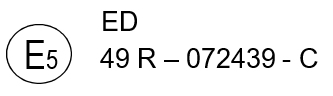
The preceding approval mark affixed to an engine or vehicle in conformity with paragraph 4. of this Regulation shows that the engine or vehicle type concerned has been approved in Sweden (E5), pursuant to Regulation No. 49, 07 series of amendments under approval number 2439. The letter after the approval number denotes the stage of requirements detailed in Table 1 (in this case Stage B). In addition, a separate suffix after the national symbol (and above the Regulation number) indicates the engine type as assigned in Table 2 (in this case "ED" for ethanol (ED95)).
Example 3
Positive ignition engine fuelled with natural gas

The preceding approval mark affixed to an engine or vehicle in conformity with paragraph 4. of this Regulation shows that the engine or vehicle type concerned has been approved in Sweden (E5), pursuant to Regulation No. 49, 07 series of amendments under approval number 2439. The letter after the approval number denotes the stage of requirements detailed in Table 1 (in this case Stage C). In addition, a separate suffix after the national symbol (and above the Regulation number) indicates the fuel range determined in paragraph 4.12.3.3.6. of this Regulation (in this case HLt).
Example 4
Positive ignition engine fuelled with LPG

The preceding approval mark affixed to an engine or vehicle in conformity with paragraph 4. of this Regulation shows that the engine or vehicle type concerned has been approved in Sweden (E5), pursuant to Regulation No. 49, 07 series of amendments under approval number 2439. The letter after the approval number denotes the stage of requirements detailed in Table 1 (in this case Stage C). In addition, a separate suffix after the national symbol (and above the Regulation number) indicates the engine type as assigned in Table 2 (in this case "Q" for LPG).
Example 5
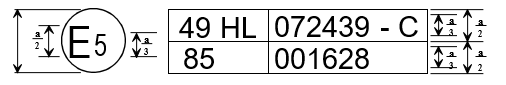
The preceding approval mark affixed to a HL natural gas engine/vehicle shows that the engine/vehicle type concerned has been approved in Sweden (E5) pursuant to Regulation No. 49 (in this case Stage C) and Regulation No. 85. The first two digits of the approval numbers indicate that, at the dates when the respective approvals were given, Regulation No. 49 included the 07 series of amendments, and Regulation No. 85 in its original form.
Table 1
Letters with reference to requirements of OBD and SCR systems
Character | NOx OTL1 | PM OTL2 | CO OTL6 | IUPR13 | Reagent quality | Additional OBD monitors12 | Power threshold requirements14 | Cold start and PM number | Implementation dates: new types | Date when Contracting Parties may refuse type approval |
A9 10 B10 | Row "phase-in period" of Tables 1 and 2 of Annex 9A | Performance monitoring3 | N/A | Phase-in7 | Phase-in4 | N/A | 20% | N/A | Date of entry into force of 06 series of UN Regulation No. 49 | 01 September 20159 31 December 201610 |
B11 | Row "phase-in period" of Tables 1 and 2 of Annex 9A | N/A | Row "phase-in period" of Table 2 of Annex 9A | N/A | Phase-in4 | N/A | 20% | N/A | 01 September
2014 | 31 December
2016 |
C | Row "general requirements" of Tables 1 and 2 of Annex 9A | Row "general requirements" of Table 1 of Annex 9A | Row "general requirements" of Table 2 of Annex 9A | General8 | General5 | Yes | 20% | N/A | 31 December
2015 | 01 September
2019 |
D | Row "general requirements" of Tables 1 and 2 of Annex 9A | Row "general requirements" of Table 1 of Annex 9A | Row "general requirements" of Table 2 of Annex 9A | General8 | General5 | Yes | 10% | N/A | 01 September
2018 | 31 December
2021 |
E | Row "general requirements" of Tables 1 and 2 of Annex 9A | Row "general requirements" of Table 1 of Annex 9A | Row "general requirements" of Table 2 of Annex 9A | General8 | General5 | Yes | 10% | Yes | Date of entry into force of 07 series of UN Regulation No. 4915 | |
Notes:
1 "NOx OTL" monitoring requirements as set out in Table 1 of Annex 9A for compression ignition and dual-fuel engines and vehicles and in Table 2 of Annex 9A for positive ignition engines and vehicles.
2 "PM OTL" monitoring requirements as set out in Table 1 of Annex 9A for compression ignition and dual-fuel engines and vehicles.
3 "Performance monitoring" requirements as set out in paragraph 2.3.2.2. of Annex 9A.
4 Reagent quality "phase-in" requirements as set out in paragraph 7.1.1.1. of Annex 11.
5 Reagent quality "general" requirements as set out in paragraph 7.1.1. of Annex 11.
6 "CO OTL" monitoring requirements as set out in Table 2 of Annex 9A for positive ignition engines and vehicles.
7 Excluding the statement required by paragraph 6.4.1. of Annex 9A.
8 Including the statement required by paragraph 6.4.1. of Annex 9A.
9 For positive-ignition engines and vehicles.
10 For compression-ignition and dual-fuel engines and vehicles.
11 Only applicable to positive-ignition engines and vehicles.
12 "Additional provisions concerning monitoring requirements" as set out in paragraph 2.3.1.2. of Annex 9A.
13 IUPR specifications are set out in Annexes 9A and 9C of this Regulation. PI engines are not subjected to IUPR.
14 ISC requirement set out in Appendix 1 to Annex 8.
15 Subject to transitional measures laid down in paragraph 13.2.2. of this Regulation.
Table 2
Engine type codes for approval marks
Engine type | Code |
Diesel fuelled CI engine | D |
Ethanol (ED95) fuelled CI engine | ED |
Ethanol (E85) fuelled PI engine | E85 |
Petrol fuelled PI engine | P |
LPG fuelled PI engine | Q |
Natural gas fuelled PI engine | See paragraph 4.12.3.3.6. of this Regulation |
Dual-fuel engines | See paragraph 4.12.3.3.7. of this Regulation |
Annex 4 Test procedure
1. Introduction
This annex is based on the world-wide harmonized heavy duty certification (WHDC), global technical regulation (gtr) No. 4).
2. Reserved
3. Definitions, symbols and abbreviations
3.1. Definitions
For the purpose of this Regulation,
3.1.2. "Delay time" means the difference in time between the change of the component to be measured at the reference point and a system response of 10 per cent of the final reading (t10) with the sampling probe being defined as the reference point. For the gaseous components, this is the transport time of the measured component from the sampling probe to the detector.
3.1.3. "Drift" means the difference between the zero or span responses of the measurement instrument after and before an emissions test.
3.1.4. "Full flow dilution method" means the process of mixing the total exhaust flow with diluent prior to separating a fraction of the diluted exhaust stream for analysis.
3.1.5. "High speed (nhi)" means the highest engine speed where 70 per cent of the declared maximum power occurs.
3.1.6. "Low speed (nlo)" means the lowest engine speed where 55 per cent of the declared maximum power occurs.
3.1.7. "Maximum power (Pmax)" means the maximum power in kW as specified by the manufacturer.
3.1.8. "Maximum torque speed" means the engine speed at which the maximum torque is obtained from the engine, as specified by the manufacturer.
3.1.9. "Normalized torque" means engine torque in per cent normalized to the maximum available torque at an engine speed.
3.1.10. "Operator demand" means an engine operator's input to control engine output. The operator may be a person (i.e., manual), or a governor
(i.e., automatic) that mechanically or electronically signals an input that demands engine output. Input may be from an accelerator pedal or signal, a throttle-control lever or signal, a fuel lever or signal, a speed lever or signal, or a governor setpoint or signal.
3.1.11. "Partial flow dilution method" means the process of separating a part from the total exhaust flow, then mixing it with an appropriate amount of diluent prior to the particulate sampling filter.
3.1.12. "Ramped steady state test cycle" means a test cycle with a sequence of steady state engine test modes with defined speed and torque criteria at each mode and defined ramps between these modes (WHSC).
3.1.13. "Rated speed" means the maximum full load speed allowed by the governor as specified by the manufacturer in his sales and service literature, or, if such a governor is not present, the speed at which the maximum power is obtained from the engine, as specified by the manufacturer in his sales and service literature.
3.1.14. "Response time" means the difference in time between the change of the component to be measured at the reference point and a system response of 90 per cent of the final reading (t90) with the sampling probe being defined as the reference point, whereby the change of the measured component is at least 60 per cent full scale (FS) and takes place in less than 0.1 second. The system response time consists of the delay time to the system and of the rise time of the system.
3.1.15. "Rise time" means the difference in time between the 10 per cent and 90 per cent response of the final reading (t90 – t10).
3.1.16. "Span response" means the mean response to a span gas during a 30 s time interval.
3.1.17. "Specific emissions" means the mass emissions expressed in g/kWh.
3.1.18. "Test cycle" means a sequence of test points each with a defined speed and torque to be followed by the engine under steady state (WHSC) or transient operating conditions (WHTC).
3.1.19. "Transformation time" means the difference in time between the change of the component to be measured at the reference point and a system response of 50 per cent of the final reading (t50) with the sampling probe being defined as the reference point. The transformation time is used for the signal alignment of different measurement instruments.
3.1.20. "Transient test cycle" means a test cycle with a sequence of normalized speed and torque values that vary relatively quickly with time (WHTC).
3.1.21. "Zero response" means the mean response to a zero gas during a 30 s time interval.
Figure 1
Definitions of system response

3.2. General symbols
Symbol | Unit | Term |
a1 | - | Slope of the regression |
a0 | - | y intercept of the regression |
A/Fst | - | Stoichiometric air to fuel ratio |
C | ppm/Vol per cent | Concentration |
cd | ppm/Vol per cent | Concentration on dry basis |
cw | ppm/Vol per cent | Concentration on wet basis |
cb | ppm/Vol per cent | Background concentration |
Cd | - | Discharge coefficient of SSV |
cgas | ppm/Vol per cent | Concentration on the gaseous components |

| particles per cubic centimetre | Average concentration of particles from the diluted exhaust gas corrected to standard conditions (273.2 K and 101.33 kPa) particles per cubic centimetre |
cs,i | particles per cubic centimetre | A discrete measurement of particle concentration in the diluted gas exhaust from the particle counter, corrected for coincidence and to standard conditions (273.2 K and 101.33 kPa) |
d | m | Diameter |
di | | Particle electrical mobility diameter (30, 50 or 100 nm) |
dV | m | Throat diameter of venturi |
D0 | m3/s | PDP calibration intercept |
D | - | Dilution factor |
t | s | Time interval |
e | | The number of particles emitted per kWh |
egas | g/kWh | Specific emission of gaseous components |
ePM | g/kWh | Specific emission of particulates |
er | g/kWh | Specific emission during regeneration |
ew | g/kWh | Weighted specific emission |
ECO2 | per cent | CO2 quench of NOx analyzer |
EE | per cent | Ethane efficiency |
EH2O | per cent | Water quench of NOx analyzer |
EM | per cent | Methane efficiency |
ENOx | per cent | Efficiency of NOx converter |
f | Hz | Data sampling rate |
fa | - | Laboratory atmospheric factor |
Fs | - | Stoichiometric factor |

| - | Mean particle concentration reduction factor of the volatile particle remover specific to the dilution settings used for the test |
Ha | g/kg | Absolute humidity of the intake air |
Hd | g/kg | Absolute humidity of the diluent |
i | - | Subscript denoting an instantaneous measurement (e.g. 1 Hz) |
k | - | Calibration factor to correct the particle number counter measurements to the level of the reference instrument where this is not applied internally within the particle number counter. Where the calibration factor is applied internally within the particle number counter, a value of 1 shall be used for k in the above equation |
kc | - | Carbon specific factor |
kf,d | m3/kg fuel | Combustion additional volume of dry exhaust |
kf,w | m3/kg fuel | Combustion additional volume of wet exhaust |
kh,D | - | Humidity correction factor for NOx for CI engines |
kh,G | - | Humidity correction factor for NOx for PI engines |
kr | - | The regeneration adjustment, according to paragraph 6.6.2., or in the case of engines without periodically regenerating after-treatment kr = 1 |
kr,d- | - | Downward regeneration adjustment factor |
kr,u | - | Upward regeneration adjustment factor |
kw,a | - | Dry to wet correction factor for the intake air |
kw,d | - | Dry to wet correction factor for the diluent |
kw,e | - | Dry to wet correction factor for the diluted exhaust gas |
kw,r | - | Dry to wet correction factor for the raw exhaust gas |
KV | - | CFV calibration function |
| - | Excess air ratio |
mb | mg | Particulate sample mass of the diluent collected |
md | kg | Mass of the diluent sample passed through the particulate sampling filters |
med | kg | Total diluted exhaust mass over the cycle |
medf | kg | Mass of equivalent diluted exhaust gas over the test cycle |
mew | kg | Total exhaust mass over the cycle |
mex | kg | Total mass of diluted exhaust gas extracted from the dilution tunnel for particle number sampling |
mf | mg | Particulate sampling filter mass |
mgas | g | Mass of gaseous emissions over the test cycle |
mp | mg | Particulate sample mass collected |
mPM | g | Mass of particulate emissions over the test cycle |
mPM,corr | g/test | Mass of particulates corrected for extraction of particle number sample flow |
mse | kg | Exhaust sample mass over the test cycle |
msed | kg | Mass of diluted exhaust gas passing the dilution tunnel |
msep | kg | Mass of diluted exhaust gas passing the particulate collection filters |
mssd | kg | Mass of secondary diluent |
M | Nm | Torque |
Ma | g/mol | Molar mass of the intake air |
Md | g/mol | Molar mass of the diluent |
Me | g/mol | Molar mass of the exhaust |
Mf | Nm | Torque absorbed by auxiliaries/equipment to be fitted |
Mgas | g/mol | Molar mass of gaseous components |
Mr | Nm | Torque absorbed by auxiliaries/equipment to be removed |
N | - | Number of particles emitted over the test cycle |
n | - | Number of measurements |
nr | - | Number of measurements with regeneration |
n | min-1 | |
nhi | min-1 | High engine speed |
nlo | min-1 | Low engine speed |
npref | min-1 | Preferred engine speed |
np | r/s | PDP pump speed |
Ncold | - | The total number of particles emitted over the WHTC cold test cycle |
Nhot | - | The total number of particles emitted over the WHTC hot test cycle |
Nin | - | Upstream particle number concentration |
Nout | - | Downstream particle number concentration |
pa | kPa | Saturation vapour pressure of engine intake air |
pb | kPa | Total atmospheric pressure |
pd | kPa | Saturation vapour pressure of the diluent |
pp | kPa | Absolute pressure |
pr | kPa | Water vapour pressure after cooling bath |
ps | kPa | Dry atmospheric pressure |
P | kW | Power |
Pf | kW | Power absorbed by auxiliaries/equipment to be fitted |
Pr | kW | Power absorbed by auxiliaries/equipment to be removed |
qex | kg/s | Particle number sample mass flow rate |
qmad | kg/s | Intake air mass flow rate on dry basis |
qmaw | kg/s | Intake air mass flow rate on wet basis |
qmCe | kg/s | Carbon mass flow rate in the raw exhaust gas |
qmCf | kg/s | Carbon mass flow rate into the engine |
qmCp | kg/s | Carbon mass flow rate in the partial flow dilution system |
qmdew | kg/s | Diluted exhaust gas mass flow rate on wet basis |
qmdw | kg/s | Diluent mass flow rate on wet basis |
qmedf | kg/s | Equivalent diluted exhaust gas mass flow rate on wet basis |
qmew | kg/s | Exhaust gas mass flow rate on wet basis |
qmex | kg/s | Sample mass flow rate extracted from dilution tunnel |
qmf | kg/s | Fuel mass flow rate |
qmp | kg/s | Sample flow of exhaust gas into partial flow dilution system |
qsw | kg/s | Mass flow rate fed back into dilution tunnel to compensate for particle number sample extraction |
qvCVS | m³/s | CVS volume rate |
qvs | dm³/min | System flow rate of exhaust analyzer system |
qvt | cm³/min | Tracer gas flow rate |
r2 | - | Coefficient of determination |
rd | - | Dilution ratio |
rD | - | Diameter ratio of SSV |
rh | - | Hydrocarbon response factor of the FID |
rm | - | Methanol response factor of the FID |
rp | - | Pressure ratio of SSV |
rs | - | Average sample ratio |
s | | Standard deviation |
| kg/m³ | Density |
e | kg/m³ | Exhaust gas density |
| - | Standard deviation |
T | K | Absolute temperature |
Ta | K | Absolute temperature of the intake air |
t | s | Time |
t10 | s | Time between step input and 10 per cent of final reading |
t50 | s | Time between step input and 50 per cent of final reading |
t90 | s | Time between step input and 90 per cent of final reading |
u | - | Ratio between the densities (or molar masses) of the gas components and the exhaust gas divided by 1,000 |
V0 | m3/r | PDP gas volume pumped per revolution |
Vs | dm³ | System volume of exhaust analyzer bench |
Wact | kWh | Actual cycle work of the test cycle |
Wact,cold | kWh | The actual cycle work over the WHTC cold test cycle according to paragraph 7.8.6. |
Wact, hot | kWh | The actual cycle work over the WHTC hot test cycle according to paragraph 7.8.6. |
Wref | kWh | Reference cycle work of the test cycle |
X0 | m3/r | PDP calibration function |
| | | | | |
3.3. Symbols and abbreviations for the fuel composition
wALF | Hydrogen content of fuel, per cent mass |
wBET | Carbon content of fuel, per cent mass |
wGAM | Sulphur content of fuel, per cent mass |
wDEL | Nitrogen content of fuel, per cent mass |
wEPS | Oxygen content of fuel, per cent mass |
| Molar hydrogen ratio (H/C) |
| Molar sulphur ratio (S/C) |
| Molar nitrogen ratio (N/C) |
| Molar oxygen ratio (O/C) |
referring to a fuel CHONS |
3.4. Symbols and abbreviations for the chemical components
C1 | Carbon 1 equivalent hydrocarbon |
CH4 | Methane |
C2H6 | Ethane |
C3H8 | Propane |
CO | Carbon monoxide |
CO2 | Carbon dioxide |
DOP | Di-octylphtalate |
HC | Hydrocarbons |
H2O | Water |
NMHC | Non-methane hydrocarbons |
NOx | Oxides of nitrogen |
NO | Nitric oxide |
NO2 | Nitrogen dioxide |
PM | Particulate matter |
3.5. Abbreviations
CFV | Critical flow venturi |
CLD | Chemiluminescent detector |
CVS | Constant volume sampling |
deNOx | NOx after-treatment system |
EGR | Exhaust gas recirculation |
ET | Evaporation tube |
FID | Flame ionization detector |
FTIR | Fourier transform infrared analyser |
GC | Gas chromatograph |
HCLD | Heated chemiluminescent detector |
HFID | Heated flame ionization detector |
LDS | Laser diode spectrometer |
LPG | Liquefied petroleum gas |
NDIR | Non-dispersive infrared (analyzer) |
NG | Natural gas |
NMC | Non-methane cutter |
OT | Outlet tube |
PDP | Positive displacement pump |
Per cent FS | Per cent of full scale |
PCF | Particle pre-classifier |
PFS | Partial flow system |
PNC | Particle number counter |
PND | Particle number diluter |
PTS | Particle transfer system |
PTT | Particle transfer tube |
SSV | Subsonic venturi |
VGT | Variable geometry turbine |
VPR | Volatile particle remover |
WHSC | World harmonised steady state cycle |
WHTC | World harmonised transient cycle |
4. General requirements
The engine system shall be so designed, constructed and assembled as to enable the engine in normal use to comply with the provisions of this annex during its useful life, as defined in this Regulation, including when installed in the vehicle.
5. Performance requirements
5.1. Emission of gaseous and particulate pollutants
The emissions of gaseous and particulate pollutants by the engine shall be determined on the WHTC and WHSC test cycles, as described in paragraph 7. The measurement systems shall meet the linearity requirements in paragraph 9.2. and the specifications in paragraph 9.3. (gaseous emissions measurement), paragraph 9.4. (particulate measurement) and in Appendix 2 to this annex.
Other systems or analyzers may be approved by the Type Approval Authority, if it is found that they yield equivalent results in accordance with paragraph 5.1.1.
5.1.1. Equivalency
The determination of system equivalency shall be based on a seven-sample pair (or larger) correlation study between the system under consideration and one of the systems of this annex.
"Results" refer to the specific cycle weighted emissions value. The correlation testing is to be performed at the same laboratory, test cell, and on the same engine, and is preferred to be run concurrently. The equivalency of the sample pair averages shall be determined by F-test and t-test statistics as described in Appendix 3, paragraph A.3.3., obtained under the laboratory test
cell and the engine conditions described above. Outliers shall be determined in accordance with ISO 5725 and excluded from the database. The systems to be used for correlation testing shall be subject to the approval by the Type Approval Authority.
5.2. Engine family
5.2.1. General
An engine family is characterized by design parameters. These shall be common to all engines within the family. The engine manufacturer may decide which engines belong to an engine family, as long as the membership criteria listed in paragraph 5.2.3. are respected. The engine family shall be approved by the Type Approval Authority. The manufacturer shall provide to the Type Approval Authority the appropriate information relating to the emission levels of the members of the engine family.
5.2.2. Special cases
In some cases there may be interaction between parameters. This shall be taken into consideration to ensure that only engines with similar exhaust emission characteristics are included within the same engine family. These cases shall be identified by the manufacturer and notified to the Type Approval Authority. It shall then be taken into account as a criterion for creating a new engine family.
In case of devices or features, which are not listed in paragraph 5.2.3. and which have a strong influence on the level of emissions, this equipment shall be identified by the manufacturer on the basis of good engineering practice, and shall be notified to the Type Approval Authority. It shall then be taken into account as a criterion for creating a new engine family.
In addition to the parameters listed in paragraph 5.2.3., the manufacturer may introduce additional criteria allowing the definition of families of more restricted size. These parameters are not necessarily parameters that have an influence on the level of emissions.
5.2.3. Parameters defining the engine family
5.2.3.1. Combustion cycle
(a) 2-stroke cycle;
(b) 4-stroke cycle;
(c) Rotary engine;
(d) Others.
5.2.3.2. Configuration of the cylinders
5.2.3.2.1. Position of the cylinders in the block
(a) V;
(b) In line;
(c) Radial;
(d) Others (F, W, etc.).
5.2.3.2.2. Relative position of the cylinders
Engines with the same block may belong to the same family as long as their bore center-to-center dimensions are the same.
5.2.3.3. Main cooling medium
(a) Air;
(b) Water;
(c) Oil.
5.2.3.4. Individual cylinder displacement
5.2.3.4.1. Engine with a unit cylinder displacement ≥ 0.75 dm³
In order for engines with a unit cylinder displacement of ≥ 0.75 dm³ to be considered to belong to the same engine family, the spread of their individual cylinder displacements shall not exceed 15 per cent of the largest individual cylinder displacement within the family.
5.2.3.4.2. Engine with a unit cylinder displacement < 0.75 dm³
In order for engines with a unit cylinder displacement of < 0.75 dm³ to be considered to belong to the same engine family, the spread of their individual cylinder displacements shall not exceed 30 per cent of the largest individual cylinder displacement within the family.
5.2.3.4.3. Engine with other unit cylinder displacement limits
Engines with an individual cylinder displacement that exceeds the limits defined in paragraphs 5.2.3.4.1. and 5.2.3.4.2. may be considered to belong to the same family with the approval of the Type Approval Authority. The approval shall be based on technical elements (calculations, simulations, experimental results etc.) showing that exceeding the limits does not have a significant influence on the exhaust emissions.
5.2.3.5. Method of air aspiration
(a) Naturally aspirated;
(b) Pressure charged;
(c) Pressure charged with charge cooler.
5.2.3.6. Fuel type
(a) Diesel;
(b) Natural gas (NG);
(c) Liquefied petroleum gas (LPG);
(d) Ethanol.
5.2.3.7. Combustion chamber type
(a) Open chamber;
(b) Divided chamber;
(c) Other types.
5.2.3.8. Ignition Type
(a) Positive ignition;
(b) Compression ignition.
5.2.3.9. Valves and porting
(a) Configuration;
(b) Number of valves per cylinder.
5.2.3.10. Fuel supply type
(a) Liquid fuel supply type:
(i) Pump and (high pressure) line and injector;
(ii) In-line or distributor pump;
(iii) Unit pump or unit injector;
(iv) Common rail;
(v) Carburettor(s);
(vi) Others.
(b) Gas fuel supply type;
(i) Gaseous;
(ii) Liquid;
(iii) Mixing units;
(iv) Others.
(c) Other types.
5.2.3.11. Miscellaneous devices
(a) Exhaust gas recirculation (EGR);
(b) Water injection;
(c) Air injection;
(d) Others.
5.2.3.12. Electronic control strategy
The presence or absence of an electronic control unit (ECU) on the engine is regarded as a basic parameter of the family.
In the case of electronically controlled engines, the manufacturer shall present the technical elements explaining the grouping of these engines in the same family, i.e. the reasons why these engines can be expected to satisfy the same emission requirements.
These elements can be calculations, simulations, estimations, description of injection parameters, experimental results, etc.
Examples of controlled features are:
(a) Timing;
(b) Injection pressure;
(c) Multiple injections;
(d) Boost pressure;
(e) VGT;
(f) EGR.
5.2.3.13. Exhaust after-treatment systems
The function and combination of the following devices are regarded as membership criteria for an engine family:
(a) Oxidation catalyst;
(b) Three-way catalyst;
(c) deNOx system with selective reduction of NOx (addition of reducing agent);
(d) Other deNOx systems;
(e) Particulate trap with passive regeneration;
(f) Particulate trap with active regeneration;
(g) Other particulate traps;
(h) Other devices.
When an engine has been certified without an after-treatment system, whether as parent engine or as member of the family, then this engine, when equipped with an oxidation catalyst, may be included in the same engine family, if it does not require different fuel characteristics.
If it requires specific fuel characteristics (e.g. particulate traps requiring special additives in the fuel to ensure the regeneration process), the decision to include it in the same family shall be based on technical elements provided by the manufacturer. These elements shall indicate that the expected emission level of the equipped engine complies with the same limit value as the non-equipped engine.
When an engine has been certified with an after-treatment system, whether as parent engine or as member of a family, whose parent engine is equipped with the same after-treatment system, then this engine, when equipped without after-treatment system, shall not be added to the same engine family.
5.2.4. Choice of the parent engine
5.2.4.1. Compression ignition engines
Once the engine family has been agreed by the Type Approval Authority, the parent engine of the family shall be selected using the primary criterion of the highest fuel delivery per stroke at the declared maximum torque speed. In the event that two or more engines share this primary criterion, the parent engine shall be selected using the secondary criterion of highest fuel delivery per stroke at rated speed.
5.2.4.2. Positive ignition engines
Once the engine family has been agreed by the Type Approval Authority, the parent engine of the family shall be selected using the primary criterion of the largest displacement. In the event that two or more engines share this primary criterion, the parent engine shall be selected using the secondary criterion in the following order of priority:
(a) The highest fuel delivery per stroke at the speed of declared rated power;
(b) The most advanced spark timing;
(c) The lowest EGR rate.
5.2.4.3. Remarks on the choice of the parent engine
The Type Approval Authority may conclude that the worst-case emission of the family can best be characterized by testing additional engines. In this case, the engine manufacturer shall submit the appropriate information to determine the engines within the family likely to have the highest emissions level.
If engines within the family incorporate other features which may be considered to affect exhaust emissions, these features shall also be identified and taken into account in the selection of the parent engine.
If engines within the family meet the same emission values over different useful life periods, this shall be taken into account in the selection of the parent engine.
6. Test conditions
6.1. Laboratory test conditions
The absolute temperature (Ta) of the engine intake air expressed in Kelvin, and the dry atmospheric pressure (ps), expressed in kPa shall be measured and the parameter fa shall be determined according to the following provisions. In multi-cylinder engines having distinct groups of intake manifolds, such as in a "Vee" engine configuration, the average temperature of the distinct groups shall be taken. The parameter fa shall be reported with the test results. For better repeatability and reproducibility of the test results, it is recommended that the parameter fa be such that: 0.93 fa 1.07.
(a) Compression-ignition engines:
Naturally aspirated and mechanically supercharged engines:
 (1)
(1)
Turbocharged engines with or without cooling of the intake air:
 (2)
(2)
(b) Positive ignition engines:
 (3)
(3)
6.2. Engines with charge air-cooling
The charge air temperature shall be recorded and shall be, at the rated speed and full load, within 5 K of the maximum charge air temperature specified by the manufacturer. The temperature of the cooling medium shall be at least 293 K (20 °C).
If a test laboratory system or external blower is used, the coolant flow rate shall be set to achieve a charge air temperature within 5 K of the maximum charge air temperature specified by the manufacturer at the rated speed and full load. Coolant temperature and coolant flow rate of the charge air cooler at the above set point shall not be changed for the whole test cycle, unless this results in unrepresentative overcooling of the charge air. The charge air cooler volume shall be based upon good engineering practice and shall be representative of the production engine's in-use installation. The laboratory system shall be designed to minimize accumulation of condensate. Any accumulated condensate shall be drained and all drains shall be completely closed before emission testing.
If the engine manufacturer specifies pressure-drop limits across the charge-air cooling system, it shall be ensured that the pressure drop across the charge-air cooling system at engine conditions specified by the manufacturer is within the manufacturer's specified limit(s). The pressure drop shall be measured at the manufacturer's specified locations.
6.3. Engine power
The basis of specific emissions measurement is engine power and cycle work as determined in accordance with paragraphs 6.3.1. to 6.3.5.
6.3.1. General engine installation
The engine shall be tested with the auxiliaries/equipment listed in Appendix 6.
If auxiliaries/equipment are not installed as required, their power shall be taken into account in accordance with paragraphs 6.3.2. to 6.3.5.
6.3.2. Auxiliaries/equipment to be fitted for the emissions test
If it is inappropriate to install the auxiliaries/equipment required according to Appendix 6 to this annex on the test bench, the power absorbed by them shall be determined and subtracted from the measured engine power (reference and actual) over the whole engine speed range of the WHTC and over the test speeds of the WHSC.
6.3.3. Auxiliaries/equipment to be removed for the test
Where the auxiliaries/equipment not required according to Appendix 6 to this annex cannot be removed, the power absorbed by them may be determined and added to the measured engine power (reference and actual) over the whole engine speed range of the WHTC and over the test speeds of the WHSC. If this value is greater than 3 per cent of the maximum power at the test speed it shall be demonstrated to the Type Approval Authority.
6.3.4. Determination of auxiliary power
The power absorbed by the auxiliaries/equipment needs only be determined, if:
(a) Auxiliaries/equipment required according to Appendix 6 to this annex, are not fitted to the engine;
and/or
(b) Auxiliaries/equipment not required according to Appendix 6 to this annex, are fitted to the engine.
The values of auxiliary power and the measurement/calculation method for determining auxiliary power shall be submitted by the engine manufacturer for the whole operating area of the test cycles, and approved by the Type Approval Authority.
6.3.5. Engine cycle work
The calculation of reference and actual cycle work (see paragraphs 7.4.8. and 7.8.6.) shall be based upon engine power according to paragraph 6.3.1. In this case, Pf and Pr of equation 4 are zero, and P equals Pm.
If auxiliaries/equipment are installed according to paragraphs 6.3.2. and/or 6.3.3., the power absorbed by them shall be used to correct each instantaneous cycle power value Pm,i, as follows:
 (4)
(4)
Where:
Pm,i is the measured engine power, kW
Pf,i is the power absorbed by auxiliaries/equipment to be fitted, kW
Pr,i is the power absorbed by auxiliaries/equipment to be removed, kW.
6.4. Engine air intake system
An engine air intake system or a test laboratory system shall be used presenting an air intake restriction within 300 Pa of the maximum value specified by the manufacturer for a clean air cleaner at the rated speed and full load. The static differential pressure of the restriction shall be measured at the location specified by the manufacturer.
6.5. Engine exhaust system
An engine exhaust system or a test laboratory system shall be used presenting an exhaust backpressure within 80 to 100 per cent of the maximum value specified by the manufacturer at the rated speed and full load. If the maximum restriction is 5 kPa or less, the set point shall be no less than 1.0 kPa from the maximum. The exhaust system shall conform to the requirements for exhaust gas sampling, as set out in paragraphs 9.3.10. and 9.3.11.
6.6. Engine with exhaust after-treatment system
If the engine is equipped with an exhaust after-treatment system, the exhaust pipe shall have the same diameter as found in-use, or as specified by the manufacturer, for at least four pipe diameters upstream of the expansion section containing the after-treatment device. The distance from the exhaust manifold flange or turbocharger outlet to the exhaust after-treatment system shall be the same as in the vehicle configuration or within the distance specifications of the manufacturer. The exhaust backpressure or restriction shall follow the same criteria as above, and may be set with a valve. For variable-restriction after-treatment devices, the maximum exhaust restriction is defined at the after-treatment condition (degreening/ageing and regeneration/loading level) specified by the manufacturer. If the maximum restriction is 5 kPa or less, the set point shall be no less than 1.0 kPa from the maximum. The after-treatment container may be removed during dummy tests and during engine mapping, and replaced with an equivalent container having an inactive catalyst support.
The emissions measured on the test cycle shall be representative of the emissions in the field. In the case of an engine equipped with an exhaust after-treatment system that requires the consumption of a reagent, the reagent used for all tests shall be declared by the manufacturer.
Engines equipped with exhaust after-treatment systems with continuous regeneration do not require a special test procedure, but the regeneration process needs to be demonstrated according to paragraph 6.6.1.
For engines equipped with exhaust after-treatment systems that are regenerated on a periodic basis, as described in paragraph 6.6.2., emission results shall be adjusted to account for regeneration events. In this case, the average emission depends on the frequency of the regeneration event in terms of fraction of tests during which the regeneration occurs.
6.6.1. Continuous regeneration
The emissions shall be measured on an after-treatment system that has been stabilized so as to result in repeatable emissions behaviour. The regeneration process shall occur at least once during the WHTC hot start test and the manufacturer shall declare the normal conditions under which regeneration occurs (soot load, temperature, exhaust back-pressure, etc.).
In order to demonstrate that the regeneration process is continuous, at least three WHTC hot start tests shall be conducted. For the purpose of this demonstration, the engine shall be warmed up in accordance with paragraph 7.4.1., the engine be soaked according to paragraph 7.6.3. and the first WHTC hot start test be run. The subsequent hot start tests shall be started after soaking according to paragraph 7.6.3. During the tests, exhaust temperatures and pressures shall be recorded (temperature before and after the after-treatment system, exhaust back pressure, etc.).
If the conditions declared by the manufacturer occur during the tests and the results of the three (or more) WHTC hot start tests do not scatter by more than ±25 per cent or 0.005 g/kWh, whichever is greater, the after-treatment system is considered to be of the continuous regeneration type, and the general test provisions of paragraph 7.6. (WHTC) and paragraph 7.7. (WHSC) apply.
If the exhaust after-treatment system has a security mode that shifts to a periodic regeneration mode, it shall be checked according to paragraph 6.6.2. For that specific case, the applicable emission limits may be exceeded and would not be weighted.
6.6.2. Periodic regeneration
For an exhaust after-treatment based on a periodic regeneration process, the emissions shall be measured on at least three WHTC hot start tests, one with and two without a regeneration event on a stabilized after-treatment system, and the results be weighted in accordance with equation 5.
The regeneration process shall occur at least once during the WHTC hot start test. The engine may be equipped with a switch capable of preventing or permitting the regeneration process provided this operation has no effect on the original engine calibration.
The manufacturer shall declare the normal parameter conditions under which the regeneration process occurs (soot load, temperature, exhaust back-pressure, etc.) and its duration. The manufacturer shall also provide the frequency of the regeneration event in terms of number of tests during which the regeneration occurs compared to number of tests without regeneration. The exact procedure to determine this frequency shall be based upon in-use data using good engineering judgement, and shall be agreed by the type approval or certification authority.
The manufacturer shall provide an after-treatment system that has been loaded in order to achieve regeneration during a WHTC test. For the purpose of this testing, the engine shall be warmed up in accordance with paragraph 7.4.1., the engine be soaked according to paragraph 7.6.3. and the WHTC hot start test be started. Regeneration shall not occur during the engine warm-up.
Average specific emissions between regeneration phases shall be determined from the arithmetic mean of several approximately equidistant WHTC hot start test results (g/kWh). As a minimum, at least one WHTC hot start test as close as possible prior to a regeneration test and one WHTC hot start test immediately after a regeneration test shall be conducted. As an alternative, the manufacturer may provide data to show that the emissions remain constant (25 per cent or 0.005 g/kWh, whichever is greater) between regeneration phases. In this case, the emissions of only one WHTC hot start test may be used.
During the regeneration test, all the data needed to detect regeneration shall be recorded (CO or NOx emissions, temperature before and after the after-treatment system, exhaust back pressure, etc.).
During the regeneration test, the applicable emission limits may be exceeded.
The test procedure is schematically shown in Figure 2.
Figure 2
Scheme of periodic regeneration

The WHTC hot start emissions shall be weighted as follows:
 (5)
(5)
Where:
n is the number of WHTC hot start tests without regeneration
nr is the number of WHTC hot start tests with regeneration (minimum one test)
 is the average specific emission without regeneration, g/kWh
 is the average specific emission with regeneration, g/kWh
For the determination of , the following provisions apply:
(a) If regeneration takes more than one hot start WHTC, consecutive full hot start WHTC tests shall be conducted and emissions continued to be measured without soaking and without shutting the engine off, until regeneration is completed, and the average of the hot start WHTC tests be calculated;
(b) If regeneration is completed during any hot start WHTC, the test shall be continued over its entire length.
In agreement with the Type Approval Authority, the regeneration adjustment factors may be applied either multiplicative (c) or additive (d) based upon good engineering analysis.
(c) The multiplicative adjustment factors shall be calculated as follows:
 (upward) (6)
 (downward) (6a)
(d) The additive adjustment factors shall be calculated as follows:
kr,u = ew - e (upward) (7)
kr,d = ew - er (downward) (8)
With reference to the specific emission calculations in paragraph 8.6.3., the regeneration adjustment factors shall be applied, as follows:
(e) For a test without regeneration, kr,u shall be multiplied with or be added to, respectively, the specific emission e in equations 69 or 70;
(f) For a test with regeneration, kr,d shall be multiplied with or be added to, respectively, the specific emission e in equations 69 or 70.
At the request of the manufacturer, the regeneration adjustment factors:
(g) May be extended to other members of the same engine family;
(h) May be extended to other engine families using the same after-treatment system with the prior approval of the type approval or certification authority based on technical evidence to be supplied by the manufacturer, that the emissions are similar.
6.7. Cooling system
An engine cooling system with sufficient capacity to maintain the engine at normal operating temperatures prescribed by the manufacturer shall be used.
6.8. Lubricating oil
The lubricating oil shall be specified by the manufacturer and be representative of lubricating oil available on the market; the specifications of the lubricating oil used for the test shall be recorded and presented with the results of the test.
6.9. Specification of the reference fuel
The reference fuels are specified in Annex 5.
The fuel temperature shall be in accordance with the manufacturer's recommendations.
6.10. Crankcase emissions
No crankcase emissions shall be discharged directly into the ambient atmosphere, with the following exception: engines equipped with turbochargers, pumps, blowers, or superchargers for air induction may discharge crankcase emissions to the ambient atmosphere if the emissions are added to the exhaust emissions (either physically or mathematically) during all emission testing. Manufacturers taking advantage of this exception shall install the engines so that all crankcase emission can be routed into the emissions sampling system.
For the purpose of this paragraph, crankcase emissions that are routed into the exhaust upstream of exhaust after-treatment during all operation are not considered to be discharged directly into the ambient atmosphere.
Open crankcase emissions shall be routed into the exhaust system for emission measurement, as follows:
(a) The tubing materials shall be smooth-walled, electrically conductive, and not reactive with crankcase emissions. Tube lengths shall be minimized as far as possible;
(b) The number of bends in the laboratory crankcase tubing shall be minimized, and the radius of any unavoidable bend shall be maximized;
(c) The laboratory crankcase exhaust tubing shall be heated, thin-walled or insulated and shall meet the engine manufacturer's specifications for crankcase back pressure;
(d) The crankcase exhaust tubing shall connect into the raw exhaust downstream of any after-treatment system, downstream of any installed exhaust restriction, and sufficiently upstream of any sample probes to ensure complete mixing with the engine's exhaust before sampling. The crankcase exhaust tube shall extend into the free stream of exhaust to avoid boundary-layer effects and to promote mixing. The crankcase exhaust tube's outlet may orient in any direction relative to the raw exhaust flow.
6.11. Paragraphs 6.11.1. and 6.11.2. shall apply to positive-ignition engines fuelled with petrol or E85.
6.11.1. The pressure in the crankcase shall be measured over the emissions test cycles at an appropriate location. It shall be measured at the dip-stick hole with an inclined-tube manometer.
6.11.1.1. The pressure in the intake manifold shall be measured to within ±1 kPa.
6.11.1.2. The pressure measured in the crankcase shall be measured to within ±0,01 kPa.
6.11.2. Compliance with paragraph 6.10. shall be deemed satisfactory if, in every condition of measurement set out in paragraph 6.11.1., the pressure measured in the crankcase does not exceed the atmospheric pressure prevailing at the time of measurement.
7. Test procedures
7.1. Principles of emissions measurement
To measure the specific emissions, the engine shall be operated over the test cycles defined in paragraphs 7.2.1. and 7.2.2. The measurement of specific emissions requires the determination of the mass of components in the exhaust and the corresponding engine cycle work. The components are determined by the sampling methods described in paragraphs 7.1.1. and 7.1.2.
7.1.1. Continuous sampling
In continuous sampling, the component's concentration is measured continuously from raw or dilute exhaust. This concentration is multiplied by the continuous (raw or dilute) exhaust flow rate at the emission sampling location to determine the component's mass flow rate. The component's emission is continuously summed over the test cycle. This sum is the total mass of the emitted component.
7.1.2. Batch sampling
In batch sampling, a sample of raw or dilute exhaust is continuously extracted and stored for later measurement. The extracted sample shall be proportional to the raw or dilute exhaust flow rate. Examples of batch sampling are collecting diluted gaseous components in a bag and collecting particulate matter (PM) on a filter. The batch sampled concentrations are multiplied by the total exhaust mass or mass flow (raw or dilute) from which it was extracted during the test cycle. This product is the total mass or mass flow of the emitted component. To calculate the PM concentration, the PM deposited onto a filter from proportionally extracted exhaust shall be divided by the amount of filtered exhaust.
7.1.3. Measurement procedures
This annex applies two measurement procedures that are functionally equivalent. Both procedures may be used for both the WHTC and the WHSC test cycle:
(a) The gaseous components are sampled continuously in the raw exhaust gas, and the particulates are determined using a partial flow dilution system;
(b) The gaseous components and the particulates are determined using a full flow dilution system (CVS system).
Any combination of the two principles (e.g. raw gaseous measurement and full flow particulate measurement) is permitted.
7.2. Test cycles
7.2.1. Transient test cycle WHTC
The transient test cycle WHTC is listed in Appendix 1 as a second-by-second sequence of normalized speed and torque values. In order to perform the test on an engine test cell, the normalized values shall be converted to the actual values for the individual engine under test based on the engine-mapping curve. The conversion is referred to as denormalization, and the test cycle so developed as the reference cycle of the engine to be tested. With those references speed and torque values, the cycle shall be run on the test cell, and the actual speed, torque and power values shall be recorded. In order to validate the test run, a regression analysis between reference and actual speed, torque and power values shall be conducted upon completion of the test.
For calculation of the brake specific emissions, the actual cycle work shall be calculated by integrating actual engine power over the cycle. For cycle validation, the actual cycle work shall be within prescribed limits of the reference cycle work.
For the gaseous pollutants, continuous sampling (raw or dilute exhaust gas) or batch sampling (dilute exhaust gas) may be used. The particulate sample shall be diluted with a conditioned diluent (such as ambient air), and collected on a single suitable filter. The WHTC is shown schematically in Figure 3.
Figure 3
WHTC test cycle

7.2.2. Ramped steady state test cycle WHSC
The ramped steady state test cycle WHSC consists of a number of normalized speed and load modes which shall be converted to the reference values for the individual engine under test based on the engine-mapping curve. The engine shall be operated for the prescribed time in each mode, whereby engine speed and load shall be changed linearly within 20 1 seconds. In order to validate the test run, a regression analysis between reference and actual speed, torque and power values shall be conducted upon completion of the test.
The concentration of each gaseous pollutant, exhaust flow and power output shall be determined over the test cycle. The gaseous pollutants may be recorded continuously or sampled into a sampling bag. The particulate sample shall be diluted with a conditioned diluent (such as ambient air). One sample over the complete test procedure shall be taken, and collected on a single suitable filter.
For calculation of the brake specific emissions, the actual cycle work shall be calculated by integrating actual engine power over the cycle.
The WHSC is shown in Table 1. Except for mode 1, the start of each mode is defined as the beginning of the ramp from the previous mode.
Table 1
WHSC test cycle
Mode | Normalized speed (per cent) | Normalized torque (per cent) | Mode length (s) incl. 20 s ramp |
1 | 0 | 0 | 210 |
2 | 55 | 100 | 50 |
3 | 55 | 25 | 250 |
4 | 55 | 70 | 75 |
5 | 35 | 100 | 50 |
6 | 25 | 25 | 200 |
7 | 45 | 70 | 75 |
8 | 45 | 25 | 150 |
9 | 55 | 50 | 125 |
10 | 75 | 100 | 50 |
11 | 35 | 50 | 200 |
12 | 35 | 25 | 250 |
13 | 0 | 0 | 210 |
| | | |
Sum | | | 1,895 |
7.3. General test sequence
The following flow chart outlines the general guidance that should be followed during testing. The details of each step are described in the relevant paragraphs. Deviations from the guidance are permitted where appropriate, but the specific requirements of the relevant paragraphs are mandatory.
For the WHTC, the test procedure consists of a cold start test following either natural or forced cool-down of the engine, a hot soak period and a hot start test.
For the WHSC, the test procedure consists of a hot start test following engine preconditioning at WHSC mode 9.
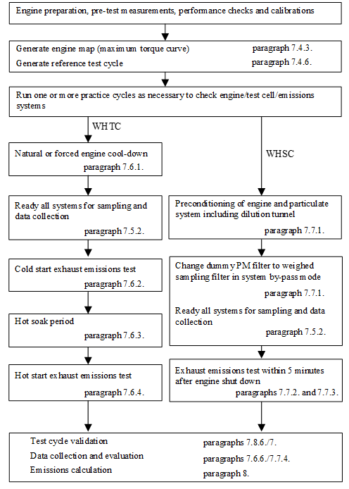
7.4. Engine mapping and reference cycle
Pre-test engine measurements, pre-test engine performance checks and pre-test system calibrations shall be made prior to the engine mapping procedure in line with the general test sequence shown in paragraph 7.3.
As basis for WHTC and WHSC reference cycle generation, the engine shall be mapped under full load operation for determining the speed vs. maximum torque and speed vs. maximum power curves. The mapping curve shall be used for denormalizing engine speed (paragraph 7.4.6.) and engine torque (paragraph 7.4.7.).
7.4.1. Engine warm-up
The engine shall be warmed up between 75 per cent and 100 per cent of its maximum power or according to the recommendation of the manufacturer and good engineering judgment. Towards the end of the warm up it shall be operated in order to stabilize the engine coolant and lube oil temperatures to within 2 per cent of its mean values for at least 2 minutes or until the engine thermostat controls engine temperature.
7.4.2. Determination of the mapping speed range
The minimum and maximum mapping speeds are defined as follows:
Minimum mapping speed = idle speed
Maximum mapping speed = nhi x 1.02 or speed where full load torque drops off to zero, whichever is smaller.
7.4.3. Engine mapping curve
When the engine is stabilized according to paragraph 7.4.1., the engine mapping shall be performed according to the following procedure.
(a) The engine shall be unloaded and operated at idle speed;
(b) The engine shall be operated with maximum operator demand at minimum mapping speed;
(c) The engine speed shall be increased at an average rate of 8 ± 1 min-1/s from minimum to maximum mapping speed, or at a constant rate such that it takes 4 to 6 minutes to sweep from minimum to maximum mapping speed. Engine speed and torque points shall be recorded at a sample rate of at least one point per second.
When selecting option (b) in paragraph 7.4.7. for determining negative reference torque, the mapping curve may directly continue with minimum operator demand from maximum to minimum mapping speed.
7.4.4. Alternate mapping
If a manufacturer believes that the above mapping techniques are unsafe or unrepresentative for any given engine, alternate mapping techniques may be used. These alternate techniques shall satisfy the intent of the specified mapping procedures to determine the maximum available torque at all engine speeds achieved during the test cycles. Deviations from the mapping techniques specified in this paragraph for reasons of safety or representativeness shall be approved by the Type Approval Authority along with the justification for their use. In no case, however, the torque curve shall be run by descending engine speeds for governed or turbocharged engines.
7.4.5. Replicate tests
An engine need not be mapped before each and every test cycle. An engine shall be remapped prior to a test cycle if:
(a) An unreasonable amount of time has transpired since the last map, as determined by engineering judgement; or
(b) Physical changes or recalibrations have been made to the engine which potentially affect engine performance.
7.4.6. Denormalization of engine speed
For generating the reference cycles, the normalized speeds of Appendix 1 (WHTC) and Table 1 (WHSC) shall be denormalized using the following equation:
nref = nnorm x (0.45 x nlo + 0.45 x npref + 0.1 x nhi − nidle) x 2.0327 + nidle (9)
For determination of npref, the integral of the maximum torque shall be calculated from nidle to n95h from the engine mapping curve, as determined in accordance with paragraph 7.4.3.
The engine speeds in Figures 4 and 5 are defined, as follows:
nnorm is the normalized speed in Appendix 1 and Table 1 divided by 100
nlo is the lowest speed where the power is 55 per cent of maximum power
npref is the engine speed where the integral of max. mapped torque is 51 per cent of the whole integral between nidle and n95h
nhi is the highest speed where the power is 70 per cent of maximum power
nidle is the idle speed
n95h is the highest speed where the power is 95 per cent of maximum power
For engines (mainly positive ignition engines) with a steep governor droop curve, where fuel cut off does not permit to operate the engine up to nhi or n95h, the following provisions apply:
nhi in equation 9 is replaced with nPmax 1.02
n95h is replaced with nPmax 1.02
Figure 4:
Definition of test speeds

Figure 5
Definition of npref

7.4.7. Denormalization of engine torque
The torque values in the engine dynamometer schedule of Appendix 1 to this annex (WHTC) and in Table 1 (WHSC) are normalized to the maximum torque at the respective speed. For generating the reference cycles, the torque values for each individual reference speed value as determined in paragraph 7.4.6. shall be denormalized, using the mapping curve determined according to paragraph 7.4.3., as follows:
 (10)
(10)
Where:
Mnorm,i is the normalized torque, per cent
Mmax,i is the maximum torque from the mapping curve, Nm
Mf,i is the torque absorbed by auxiliaries/equipment to be fitted, Nm
Mr,i is the torque absorbed by auxiliaries/equipment to be removed, Nm
If auxiliaries/equipment are fitted in accordance with paragraph 6.3.1. and Appendix 6 to this annex, Mf and Mr are zero.
The negative torque values of the motoring points (m in Appendix 1 to this annex) shall take on, for purposes of reference cycle generation, reference values determined in either of the following ways:
(a) Negative 40 per cent of the positive torque available at the associated speed point;
(b) Mapping of the negative torque required to motor the engine from maximum to minimum mapping speed;
(c) Determination of the negative torque required to motor the engine at idle and at nhi and linear interpolation between these two points.
7.4.8. Calculation of reference cycle work
Reference cycle work shall be determined over the test cycle by synchronously calculating instantaneous values for engine power from reference speed and reference torque, as determined in paragraphs 7.4.6. and 7.4.7. Instantaneous engine power values shall be integrated over the test cycle to calculate the reference cycle work Wref (kWh). If auxiliaries are not fitted in accordance with paragraph 6.3.1., the instantaneous power values shall be corrected using equation 4 in paragraph 6.3.5.
The same methodology shall be used for integrating both reference and actual engine power. If values are to be determined between adjacent reference or adjacent measured values, linear interpolation shall be used. In integrating the actual cycle work, any negative torque values shall be set equal to zero and included. If integration is performed at a frequency of less than 5 Hz, and if, during a given time segment, the torque value changes from positive to negative or negative to positive, the negative portion shall be computed and set equal to zero. The positive portion shall be included in the integrated value.
7.5. Pre-test procedures
7.5.1. Installation of the measurement equipment
The instrumentation and sample probes shall be installed as required. The tailpipe shall be connected to the full flow dilution system, if used.
7.5.2. Preparation of measurement equipment for sampling
The following steps shall be taken before emission sampling begins:
(a) Leak checks shall be performed within 8 hours prior to emission sampling according to paragraph 9.3.4.;
(b) For batch sampling, clean storage media shall be connected, such as evacuated bags;
(c) All measurement instruments shall be started according to the instrument manufacturer's instructions and good engineering judgment;
(d) Dilution systems, sample pumps, cooling fans, and the data-collection system shall be started;
(e) The sample flow rates shall be adjusted to desired levels, using bypass flow, if desired;
(f) Heat exchangers in the sampling system shall be pre-heated or pre-cooled to within their operating temperature ranges for a test;
(g) Heated or cooled components such as sample lines, filters, coolers, and pumps shall be allowed to stabilize at their operating temperatures;
(h) Exhaust dilution system flow shall be switched on at least 10 minutes before a test sequence;
(i) Any electronic integrating devices shall be zeroed or re-zeroed, before the start of any test interval.
7.5.3. Checking the gas analyzers
Gas analyzer ranges shall be selected. Emission analyzers with automatic or manual range switching are permitted. During the test cycle, the range of the emission analyzers shall not be switched. At the same time the gains of an analyzer's analogue operational amplifier(s) may not be switched during the test cycle.
Zero and span response shall be determined for all analyzers using internationally-traceable gases that meet the specifications of paragraph 9.3.3. FID analyzers shall be spanned on a carbon number basis of one (C1).
7.5.4. Preparation of the particulate sampling filter
At least one hour before the test, the filter shall be placed in a petri dish, which is protected against dust contamination and allows air exchange, and placed in a weighing chamber for stabilization. At the end of the stabilization period, the filter shall be weighed and the tare weight shall be recorded. The filter shall then be stored in a closed petri dish or sealed filter holder until needed for testing. The filter shall be used within eight hours of its removal from the weighing chamber.
7.5.5. Adjustment of the dilution system
The total diluted exhaust gas flow of a full flow dilution system or the diluted exhaust gas flow through a partial flow dilution system shall be set to eliminate water condensation in the system, and to obtain a filter face temperature between 315 K (42 °C) and 325 K (52 °C).
7.5.6. Starting the particulate sampling system
The particulate sampling system shall be started and operated on by-pass. The particulate background level of the diluent may be determined by sampling the diluent prior to the entrance of the exhaust gas into the dilution tunnel. The measurement may be done prior to or after the test. If the measurement is done both at the beginning and at the end of the cycle, the values may be averaged. If a different sampling system is used for background measurement, the measurement shall be done in parallel to the test run.
7.6. WHTC cycle run
7.6.1. Engine cool-down
A natural or forced cool-down procedure may be applied. For forced cool-down, good engineering judgment shall be used to set up systems to send cooling air across the engine, to send cool oil through the engine lubrication system, to remove heat from the coolant through the engine cooling system, and to remove heat from an exhaust after-treatment system. In the case of a forced after-treatment system cool down, cooling air shall not be applied until the after-treatment system has cooled below its catalytic activation temperature. Any cooling procedure that results in unrepresentative emissions is not permitted.
7.6.2. Cold start test
The cold-start test shall be started when the temperatures of the engine's lubricant, coolant, and after-treatment systems are all between 293 and 303 K (20 and 30 °C). The engine shall be started using one of the following methods:
(a) The engine shall be started as recommended in the owner’s manual using a production starter motor and adequately charged battery or a suitable power supply; or
(b) The engine shall be started by using the dynamometer. The engine shall be motored within 25 per cent of its typical in-use cranking speed. Cranking shall be stopped within 1 second after the engine is running. If the engine does not start after 15 seconds of cranking, cranking shall be stopped and the reason for the failure to start determined, unless the owner’s manual or the service-repair manual describes the longer cranking time as normal.
7.6.3. Hot soak period
Immediately upon completion of the cold start test, the engine shall be conditioned for the hot start test using a 10 ± 1 minute hot soak period.
7.6.4. Hot start test
The engine shall be started at the end of the hot soak period as defined in paragraph 7.6.3. using the starting methods given in paragraph 7.6.2.
7.6.5. Test sequence
The test sequence of both cold start and hot start test shall commence at the start of the engine. After the engine is running, cycle control shall be initiated so that engine operation matches the first set point of the cycle.
The WHTC shall be performed according to the reference cycle as set out in paragraph 7.4. Engine speed and torque command set points shall be issued at 5 Hz (10 Hz recommended) or greater. The set points shall be calculated by linear interpolation between the 1 Hz set points of the reference cycle. Actual engine speed and torque shall be recorded at least once every second during the test cycle (1 Hz), and the signals may be electronically filtered.
7.6.6. Collection of emission relevant data
At the start of the test sequence, the measuring equipment shall be started, simultaneously:
(a) Start collecting or analyzing diluent, if a full flow dilution system is used;
(b) Start collecting or analyzing raw or diluted exhaust gas, depending on the method used;
(c) Start measuring the amount of diluted exhaust gas and the required temperatures and pressures;
(d) Start recording the exhaust gas mass flow rate, if raw exhaust gas analysis is used;
(e) Start recording the feedback data of speed and torque of the dynamometer.
If raw exhaust measurement is used, the emission concentrations ((NM)HC, CO and NOx) and the exhaust gas mass flow rate shall be measured continuously and stored with at least 2 Hz on a computer system. All other data may be recorded with a sample rate of at least 1 Hz. For analogue analyzers the response shall be recorded, and the calibration data may be applied online or offline during the data evaluation.
If a full flow dilution system is used, HC and NOx shall be measured continuously in the dilution tunnel with a frequency of at least 2 Hz. The average concentrations shall be determined by integrating the analyzer signals over the test cycle. The system response time shall be no greater than 20 seconds, and shall be coordinated with CVS flow fluctuations and sampling time/test cycle offsets, if necessary. CO, CO2, and NMHC may be determined by integration of continuous measurement signals or by analyzing the concentrations in the sample bag, collected over the cycle. The concentrations of the gaseous pollutants in the diluent shall be determined prior to the point where the exhaust enters into the dilution tunnel by integration or by collecting into the background bag. All other parameters that need to be measured shall be recorded with a minimum of one measurement per second (1 Hz).
7.6.7. Particulate sampling
At the start of the test sequence, the particulate sampling system shall be switched from by-pass to collecting particulates.
If a partial flow dilution system is used, the sample pump(s) shall be controlled, so that the flow rate through the particulate sample probe or transfer tube is maintained proportional to the exhaust mass flow rate as determined in accordance with paragraph 9.4.6.1.
If a full flow dilution system is used, the sample pump(s) shall be adjusted so that the flow rate through the particulate sample probe or transfer tube is maintained at a value within ±2.5 per cent of the set flow rate. If flow compensation (i.e., proportional control of sample flow) is used, it shall be demonstrated that the ratio of main tunnel flow to particulate sample flow does not change by more than ±2.5 per cent of its set value (except for the first 10 seconds of sampling). The average temperature and pressure at the gas meter(s) or flow instrumentation inlet shall be recorded. If the set flow rate cannot be maintained over the complete cycle within ±2.5 per cent because of high particulate loading on the filter, the test shall be voided. The test shall be rerun using a lower sample flow rate.
7.6.8. Engine stalling and equipment malfunction
If the engine stalls anywhere during the cold start test, the test shall be voided. The engine shall be preconditioned and restarted according to the requirements of paragraph 7.6.2., and the test repeated.
If the engine stalls anywhere during the hot start test, the hot start test shall be voided. The engine shall be soaked according to paragraph 7.6.3., and the hot start test repeated. In this case, the cold start test need not be repeated.
If a malfunction occurs in any of the required test equipment during the test cycle, the test shall be voided and repeated in line with the above provisions.
7.7. WHSC cycle run
7.7.1. Preconditioning the dilution system and the engine
The dilution system and the engine shall be started and warmed up in accordance with paragraph 7.4.1. After warm-up, the engine and sampling system shall be preconditioned by operating the engine at mode 9 (see paragraph 7.2.2., Table 1) for a minimum of 10 minutes while simultaneously operating the dilution system. Dummy particulate emissions samples may be collected. Those sample filters need not be stabilized or weighed, and may be discarded. Flow rates shall be set at the approximate flow rates selected for testing. The engine shall be shut off after preconditioning.
7.7.2. Engine starting
5 1 minutes after completion of preconditioning at mode 9 as described in paragraph 7.7.1., the engine shall be started according to the manufacturer's recommended starting procedure in the owner's manual, using either a production starter motor or the dynamometer in accordance with paragraph 7.6.2.
7.7.3. Test sequence
The test sequence shall commence after the engine is running and within one minute after engine operation is controlled to match the first mode of the cycle (idle).
The WHSC shall be performed according to the order of test modes listed in Table 1 of paragraph 7.2.2.
7.7.4. Collection of emission relevant data
At the start of the test sequence, the measuring equipment shall be started, simultaneously:
(a) Start collecting or analyzing diluent, if a full flow dilution system is used;
(b) Start collecting or analyzing raw or diluted exhaust gas, depending on the method used;
(c) Start measuring the amount of diluted exhaust gas and the required temperatures and pressures;
(d) Start recording the exhaust gas mass flow rate, if raw exhaust gas analysis is used;
(e) Start recording the feedback data of speed and torque of the dynamometer.
If raw exhaust measurement is used, the emission concentrations ((NM)HC, CO and NOx) and the exhaust gas mass flow rate shall be measured continuously and stored with at least 2 Hz on a computer system. All other data may be recorded with a sample rate of at least 1 Hz. For analogue analyzers the response shall be recorded, and the calibration data may be applied online or offline during the data evaluation.
If a full flow dilution system is used, HC and NOx shall be measured continuously in the dilution tunnel with a frequency of at least 2 Hz. The average concentrations shall be determined by integrating the analyzer signals over the test cycle. The system response time shall be no greater than 20 seconds, and shall be coordinated with CVS flow fluctuations and sampling time/test cycle offsets, if necessary. CO, CO2, and NMHC may be determined by integration of continuous measurement signals or by analyzing the concentrations in the sample bag, collected over the cycle. The concentrations of the gaseous pollutants in the diluent shall be determined prior to the point where the exhaust enters into the dilution tunnel by integration or by collecting into the background bag. All other parameters that need to be measured shall be recorded with a minimum of one measurement per second (1 Hz).
7.7.5. Particulate sampling
At the start of the test sequence, the particulate sampling system shall be switched from by-pass to collecting particulates. If a partial flow dilution system is used, the sample pump(s) shall be controlled, so that the flow rate through the particulate sample probe or transfer tube is maintained proportional to the exhaust mass flow rate as determined in accordance with paragraph 9.4.6.1.
If a full flow dilution system is used, the sample pump(s) shall be adjusted so that the flow rate through the particulate sample probe or transfer tube is maintained at a value within ±2.5 per cent of the set flow rate. If flow compensation (i.e., proportional control of sample flow) is used, it shall be demonstrated that the ratio of main tunnel flow to particulate sample flow does not change by more than ±2.5 per cent of its set value (except for the first 10 seconds of sampling). The average temperature and pressure at the gas meter(s) or flow instrumentation inlet shall be recorded. If the set flow rate cannot be maintained over the complete cycle within ±2.5 per cent because of high particulate loading on the filter, the test shall be voided. The test shall be rerun using a lower sample flow rate.
7.7.6. Engine stalling and equipment malfunction
If the engine stalls anywhere during the cycle, the test shall be voided. The engine shall be preconditioned according to paragraph 7.7.1. and restarted according to paragraph 7.7.2., and the test repeated.
If a malfunction occurs in any of the required test equipment during the test cycle, the test shall be voided and repeated in line with the above provisions.
7.8. Post-test procedures
7.8.1. Operations after test
At the completion of the test, the measurement of the exhaust gas mass flow rate, the diluted exhaust gas volume, the gas flow into the collecting bags and the particulate sample pump shall be stopped. For an integrating analyzer system, sampling shall continue until system response times have elapsed.
7.8.2. Verification of proportional sampling
For any proportional batch sample, such as a bag sample or PM sample, it shall be verified that proportional sampling was maintained according to paragraphs 7.6.7. and 7.7.5. Any sample that does not fulfil the requirements shall be voided.
7.8.3. PM conditioning and weighing
The particulate filter shall be placed into covered or sealed containers or the filter holders shall be closed, in order to protect the sample filters against ambient contamination. Thus protected, the filter shall be returned to the weighing chamber. The filter shall be conditioned for at least one hour, and then weighed according to paragraph 9.4.5. The gross weight of the filter shall be recorded.
7.8.4. Drift verification
As soon as practical but no later than 30 minutes after the test cycle is complete or during the soak period (for (b) only), the zero and span responses of the gaseous analyser ranges used shall be determined. For the purpose of this paragraph, test cycle is defined as follows:
(a) For the WHTC: the complete sequence cold – soak – hot;
(b) For the WHTC hot start test (paragraph 6.6.): the sequence soak – hot;
(c) For the multiple regeneration WHTC hot start test (paragraph 6.6.): the total number of hot start tests;
(d) For the WHSC: the test cycle.
The following provisions apply for analyser drift:
(a) The pre-test zero and span and post-test zero and span responses may be directly inserted into equation 66 of paragraph 8.6.1. without determining the drift;
(b) If the drift between the pre-test and post-test results is less than 1 per cent of full scale, the measured concentrations may be used uncorrected or may be corrected for drift according to paragraph 8.6.1.;
If the drift difference between the pre-test and post-test results is equal to or greater than 1 per cent of full scale, the test shall be voided or the measured concentrations shall be corrected for drift according to paragraph 8.6.1.
7.8.5. Analysis of gaseous bag sampling
As soon as practical, the following shall be performed:
(a) Gaseous bag samples shall be analyzed no later than 30 minutes after the hot start test is complete or during the soak period for the cold start test;
(b) Background samples shall be analyzed no later than 60 minutes after the hot start test is complete.
7.8.6. Validation of cycle work
Before calculating actual cycle work, any points recorded during engine starting shall be omitted. Actual cycle work shall be determined over the test cycle by synchronously using actual speed and actual torque values to calculate instantaneous values for engine power. Instantaneous engine power values shall be integrated over the test cycle to calculate the actual cycle work Wact (kWh). If auxiliaries/equipment are not fitted in accordance with paragraph 6.3.1., the instantaneous power values shall be corrected using equation 4 in paragraph 6.3.5.
The same methodology as described in paragraph 7.4.8. shall be used for integrating actual engine power.
The actual cycle work Wact is used for comparison to the reference cycle work Wref and for calculating the brake specific emissions (see paragraph 8.6.3.).
Wact shall be between 85 per cent and 105 per cent of Wref
7.8.7. Validation statistics of the test cycle
Linear regressions of the actual values (nact, Mact, Pact) on the reference values (nref, Mref, Pref) shall be performed for both the WHTC and the WHSC.
To minimize the biasing effect of the time lag between the actual and reference cycle values, the entire engine speed and torque actual signal sequence may be advanced or delayed in time with respect to the reference speed and torque sequence. If the actual signals are shifted, both speed and torque shall be shifted by the same amount in the same direction.
The method of least squares shall be used, with the best-fit equation having the form:
y = a1x + a0 (11)
Where:
y is the actual value of speed (min-1), torque (Nm), or power (kW)
a1 is the slope of the regression line
x is the reference value of speed (min-1), torque (Nm), or power (kW)
a0 is the y intercept of the regression line
The standard error of estimate (SEE) of y on x and the coefficient of determination (r²) shall be calculated for each regression line.
It is recommended that this analysis be performed at 1 Hz. For a test to be considered valid, the criteria of Table 2 (WHTC) or Table 3 (WHSC) shall be met.
Table 2
Regression line tolerances for the WHTC
| Speed | Torque | Power |
Standard error of estimate (SEE) of y on x | maximum 5 per cent of maximum test speed | maximum 10 per cent of maximum engine torque | maximum 10 per cent of maximum engine power |
Slope of the regression line, a1 | 0.95 to 1.03 | 0.83 - 1.03 | 0.89 - 1.03 |
Coefficient of determination, r² | minimum 0.970 | minimum 0.850 | minimum 0.910 |
y intercept of the regression line, a0 | maximum 10 per cent of idle speed | ±20 Nm or 2 per cent of maximum torque whichever is greater | ±4 kW or 2 per cent of maximum power whichever is greater |
Table 3
Regression line tolerances for the WHSC
| Speed | Torque | Power |
Standard error of estimate (SEE) of y on x | maximum 1 per cent of maximum test speed | maximum 2 per cent of maximum engine torque | maximum 2 per cent of maximum engine power |
Slope of the regression line, a1 | 0.99 to 1.01 | 0.98 - 1.02 | 0.98 - 1.02 |
Coefficient of determination, r² | minimum 0.990 | minimum 0.950 | minimum 0.950 |
y intercept of the regression line, a0 | maximum 1 per cent of maximum test speed | ±20 Nm or 2 per cent of maximum torque whichever is greater | ±4 kW or 2 per cent of maximum power whichever is greater |
For regression purposes only, point omissions are permitted where noted in Table 4 before doing the regression calculation. However, those points shall not be omitted for the calculation of cycle work and emissions. Point omission may be applied to the whole or to any part of the cycle.
Table 4
Permitted point omissions from regression analysis
Event | Conditions | Permitted point omissions |
Minimum operator demand (idle point) | nref = 0 per cent and Mref = 0 per cent and Mact > (Mref - 0.02 Mmax. mapped torque) and Mact < (Mref + 0.02 Mmax. mapped torque) | speed and power |
Minimum operator demand (motoring point) | Mref < 0 per cent | power and torque |
Minimum operator demand | nact ≤ 1.02 nref and Mact > Mref or nact > nref and Mact ≤ Mref' or nact > 1.02 nref and Mref < Mact ≤ (Mref + 0.02 Mmax. mapped torque) | power and either torque or speed |
Maximum operator demand | nact < nref and Mact ≥ Mref or nact ≥ 0.98 nref and Mact < Mref or nact < 0.98 nref and Mref > Mact ≥ (Mref - 0.02 Mmax. mapped torque) | power and either torque or speed |
8. Emission calculation
The final test result shall be rounded in one step to the number of places to the right of the decimal point indicated by the applicable emission standard plus one additional significant figure, in accordance with ASTM E 29-06B. No rounding of intermediate values leading to the final break-specific emission result is permitted.
Calculation of hydrocarbons and/or non-methane hydrocarbons is based on the following molar carbon/hydrogen/oxygen ratios (C/H/O) of the fuel:
CH1.86O0.006 for diesel (B7),
CH2.92O0.46 for ethanol for dedicated C.I. engines (ED95),
CH1.93O0.032 for petrol (E10),
CH2.74O0.385 for ethanol (E85),
CH2.525 for LPG (liquefied petroleum gas),
CH4 for NG (natural gas) and biomethane.
Examples of the calculation procedures are given in Appendix 5 to this annex.
Emissions calculation on a molar basis, in accordance with Annex 7 of gtr No. 11 concerning the exhaust emission test protocol for Non-Road Mobile Machinery (NRMM), is permitted with the prior agreement of the Type Approval Authority.
8.1. Dry/wet correction
If the emissions are measured on a dry basis, the measured concentration shall be converted to a wet basis according to the following equation:
 (12)
(12)
Where:
cd is the dry concentration in ppm or per cent volume
kw is the dry/wet correction factor (kw,a, kw,e, or kw,d depending on respective equation used)
8.1.1. Raw exhaust gas
 (13)
(13)
or
 (14)
(14)
or
 (15)
(15)
With
 (16)
(16)
and
 (17)
(17)
Where:
Ha is the intake air humidity, g water per kg dry air
wALF is the hydrogen content of the fuel, per cent mass
qmf,i is the instantaneous fuel mass flow rate, kg/s
qmad,I is the instantaneous dry intake air mass flow rate, kg/s
pr is the water vapour pressure after cooling bath, kPa
pb is the total atmospheric pressure, kPa
wDEL is the nitrogen content of the fuel, per cent mass
wEPS is the oxygen content of the fuel, per cent mass
is the molar hydrogen ratio of the fuel
cCO2 is the dry CO2 concentration, per cent
cCO is the dry CO concentration, per cent
Equations 13 and 14 are principally identical with the factor 1.008 in equations 13 and 15 being an approximation for the more accurate denominator in equation 14.
8.1.2. Diluted exhaust gas
 (18)
(18)
or
 (19)
(19)
With
 (20)
(20)
Where:
is the molar hydrogen ratio of the fuel
cCO2w is the wet CO2 concentration, per cent
cCO2d is the dry CO2 concentration, per cent
Hd is the diluent humidity, g water per kg dry air
Ha is the intake air humidity, g water per kg dry air
D is the dilution factor (see paragraph 8.5.2.3.2.)
8.1.3. Diluent
 (21)
(21)
With
 (22)
(22)
Where:
Hd is the diluent humidity, g water per kg dry air
8.2. NOx correction for humidity
As the NOx emission depends on ambient air conditions, the NOx concentration shall be corrected for humidity with the factors given in paragraph 8.2.1. or 8.2.2. The intake air humidity Ha may be derived from relative humidity measurement, dew point measurement, vapour pressure measurement or dry/wet bulb measurement using generally accepted equations.
8.2.1. Compression-ignition engines
 (23)
(23)
Where:
Ha is the intake air humidity, g water per kg dry air
8.2.2. Positive ignition engines
 (24)
(24)
Where:
Ha is the intake air humidity, g water per kg dry air
8.3. Particulate filter buoyancy correction
The sampling filter mass shall be corrected for its buoyancy in air. The buoyancy correction depends on sampling filter density, air density and the density of the balance calibration weight, and does not account for the buoyancy of the PM itself. The buoyancy correction shall be applied to both tare filter mass and gross filter mass.
If the density of the filter material is not known, the following densities shall be used:
(a) Teflon coated glass fiber filter: 2,300 kg/m3;
(b) Teflon membrane filter: 2,144 kg/m3;
(c) Teflon membrane filter with polymethylpentene support ring: 920 kg/m3.
For stainless steel calibration weights, a density of 8,000 kg/m3 shall be used. If the material of the calibration weight is different, its density shall be known.
The following equation shall be used:
 (25)
(25)
With
 (26)
(26)
Where:
muncor is the uncorrected particulate filter mass, mg
ρa is the density of the air, kg/m3
ρw is the density of balance calibration weight, kg/m3
ρf is the density of the particulate sampling filter, kg/m3
pb is the total atmospheric pressure, kPa
Ta is the air temperature in the balance environment, K
28.836 is the molar mass of the air at reference humidity (282.5 K), g/mol
8.3144 is the molar gas constant
The particulate sample mass mp used in paragraphs 8.4.3. and 8.5.3. shall be calculated as follows:
 (27)
(27)
Where:
mf,G is the buoyancy corrected gross particulate filter mass, mg
mf,T is the buoyancy corrected tare particulate filter mass, mg
8.4. Partial flow dilution (PFS) and raw gaseous measurement
The instantaneous concentration signals of the gaseous components are used for the calculation of the mass emissions by multiplication with the instantaneous exhaust mass flow rate. The exhaust mass flow rate may be measured directly, or calculated using the methods of intake air and fuel flow measurement, tracer method or intake air and air/fuel ratio measurement. Special attention shall be paid to the response times of the different instruments. These differences shall be accounted for by time aligning the signals. For particulates, the exhaust mass flow rate signals are used for controlling the partial flow dilution system to take a sample proportional to the exhaust mass flow rate. The quality of proportionality shall be checked by applying a regression analysis between sample and exhaust flow in accordance with paragraph 9.4.6.1. The complete test set up is schematically shown in Figure 6.
Figure 6
Scheme of raw/partial flow measurement system
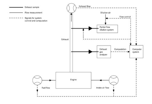
8.4.1. Determination of exhaust gas mass flow
8.4.1.1. Introduction
For calculation of the emissions in the raw exhaust gas and for controlling of a partial flow dilution system, it is necessary to know the exhaust gas mass flow rate. For the determination of the exhaust mass flow rate, one of the methods described in paragraphs 8.4.1.3. to 8.4.1.7. may be used.
8.4.1.2. Response time
For the purpose of emissions calculation, the response time of any of the methods described in paragraphs 8.4.1.3. to 8.4.1.7. shall be equal to or less than the analyzer response time of ≤ 10 seconds, as required in paragraph 9.3.5.
For the purpose of controlling of a partial flow dilution system, a faster response is required. For partial flow dilution systems with online control, the response time shall be ≤ 0.3 second. For partial flow dilution systems with look ahead control based on a pre-recorded test run, the response time of the exhaust flow measurement system shall be ≤ 5 seconds with a rise time of ≤ 1 second. The system response time shall be specified by the instrument manufacturer. The combined response time requirements for the exhaust gas flow and partial flow dilution system are indicated in paragraph 9.4.6.1.
8.4.1.3. Direct measurement method
Direct measurement of the instantaneous exhaust flow shall be done by systems, such as:
(a) Pressure differential devices, like flow nozzle, (details see ISO 5167);
(b) Ultrasonic flowmeter;
(c) Vortex flowmeter.
Precautions shall be taken to avoid measurement errors which will impact emission value errors. Such precautions include the careful installation of the device in the engine exhaust system according to the instrument manufacturers' recommendations and to good engineering practice. Especially, engine performance and emissions shall not be affected by the installation of the device.
The flowmeters shall meet the linearity requirements of paragraph 9.2.
8.4.1.4. Air and fuel measurement method
This involves measurement of the airflow and the fuel flow with suitable flowmeters. The calculation of the instantaneous exhaust gas flow shall be as follows:
qmew,i = qmaw,i + qmf,i (28)
Where:
qmew,i is the instantaneous exhaust mass flow rate, kg/s
qmaw,i is the instantaneous intake air mass flow rate, kg/s
qmf,i is the instantaneous fuel mass flow rate, kg/s
The flowmeters shall meet the linearity requirements of paragraph 9.2., but shall be accurate enough to also meet the linearity requirements for the exhaust gas flow.
8.4.1.5. Tracer measurement method
This involves measurement of the concentration of a tracer gas in the exhaust.
A known amount of an inert gas (e.g. pure helium) shall be injected into the exhaust gas flow as a tracer. The gas is mixed and diluted by the exhaust gas, but shall not react in the exhaust pipe. The concentration of the gas shall then be measured in the exhaust gas sample.
In order to ensure complete mixing of the tracer gas, the exhaust gas sampling probe shall be located at least 1 m or 30 times the diameter of the exhaust pipe, whichever is larger, downstream of the tracer gas injection point. The sampling probe may be located closer to the injection point if complete mixing is verified by comparing the tracer gas concentration with the reference concentration when the tracer gas is injected upstream of the engine.
The tracer gas flow rate shall be set so that the tracer gas concentration at engine idle speed after mixing becomes lower than the full scale of the trace gas analyzer.
The calculation of the exhaust gas flow shall be as follows:
 (29)
(29)
Where:
qmew,i is the instantaneous exhaust mass flow rate, kg/s
qvt is tracer gas flow rate, cm³/min
cmix,i is the instantaneous concentration of the tracer gas after mixing, ppm
e is the density of the exhaust gas, kg/m³ (see Table 5)
cb is the background concentration of the tracer gas in the intake air, ppm
The background concentration of the tracer gas (cb) may be determined by averaging the background concentration measured immediately before the test run and after the test run.
When the background concentration is less than 1 per cent of the concentration of the tracer gas after mixing (cmix.i) at maximum exhaust flow, the background concentration may be neglected.
The total system shall meet the linearity requirements for the exhaust gas flow of paragraph 9.2.
8.4.1.6. Airflow and air to fuel ratio measurement method
This involves exhaust mass calculation from the air flow and the air to fuel ratio. The calculation of the instantaneous exhaust gas mass flow is as follows:
 (30)
(30)
With
 (31)
(31)
 (32)
(32)
Where:
qmaw,i is the instantaneous intake air mass flow rate, kg/s
A/Fst is the stoichiometric air to fuel ratio, kg/kg
i is the instantaneous excess air ratio
cCO2d is the dry CO2 concentration, per cent
cCOd is the dry CO concentration, ppm
cHCw is the wet HC concentration, ppm
Air flow meter and analyzers shall meet the linearity requirements of paragraph 9.2., and the total system shall meet the linearity requirements for the exhaust gas flow of paragraph 9.2.
If an air to fuel ratio measurement equipment such as a zirconia type sensor is used for the measurement of the excess air ratio, it shall meet the specifications of paragraph 9.3.2.7.
8.4.1.7. Carbon balance method
This involves exhaust mass calculation from the fuel flow and the gaseous exhaust components that include carbon. The calculation of the instantaneous exhaust gas mass flow is as follows:
 (33)
(33)
With
kc= (cCO2d – cCO2d,a) x 0,5441 + cCOd/18522 + cHCw/17355 (34)
And
kfd = - 0,055586 x wALF + 0,0080021 x wDEL + 0,0070046 x wEPS (35)
Where:
qmf,i is the instantaneous fuel mass flow rate, kg/s
Ha is the intake air humidity, g water per kg dry air
wBET is the carbon content of the fuel, per cent mass
wALF is the hydrogen content of the fuel, per cent mass
wDEL is the nitrogen content of the fuel, per cent mass
wEPS is the oxygen content of the fuel, per cent mass
cCO2d is the dry CO2 concentration, per cent
cCO2d,a is the dry CO2 concentration of the intake air, per cent
cCOd is the dry CO concentration, ppm
cHCw is the wet HC concentration, ppm
8.4.2. Determination of the gaseous components
8.4.2.1. Introduction
The gaseous components in the raw exhaust gas emitted by the engine submitted for testing shall be measured with the measurement and sampling systems described in paragraph 9.3. and Appendix 2 to this annex. The data evaluation is described in paragraph 8.4.2.2.
Two calculation procedures are described in paragraphs 8.4.2.3. and 8.4.2.4., which are equivalent for the reference fuel of Annex 5. The procedure in paragraph 8.4.2.3. is more straightforward, since it uses tabulated u values for the ratio between component and exhaust gas density. The procedure in paragraph 8.4.2.4. is more accurate for fuel qualities that deviate from the specifications in Annex 5, but requires elementary analysis of the fuel composition.
8.4.2.2. Data evaluation
The emission relevant data shall be recorded and stored in accordance with paragraph 7.6.6.
For calculation of the mass emission of the gaseous components, the traces of the recorded concentrations and the trace of the exhaust gas mass flow rate shall be time aligned by the transformation time as defined in paragraph 3.1. Therefore, the response time of the exhaust gas mass flow system and each gaseous emissions analyzer shall be determined according to paragraphs 8.4.1.2. and 9.3.5., respectively, and recorded.
8.4.2.3. Calculation of mass emission based on tabulated values
The mass of the pollutants (g/test) shall be determined by calculating the instantaneous mass emissions from the raw concentrations of the pollutants and the exhaust gas mass flow, aligned for the transformation time as determined in accordance with paragraph 8.4.2.2., integrating the instantaneous values over the cycle, and multiplying the integrated values with the u values from Table 5. If measured on a dry basis, the dry/wet correction according to paragraph 8.1. shall be applied to the instantaneous concentration values before any further calculation is done.
For the calculation of NOx, the mass emission shall be multiplied, where applicable, with the humidity correction factor kh,D, or kh,G, as determined according to paragraph 8.2.
The following equation shall be applied:
 (36)
(36)
Where:
ugas is the respective value of the exhaust component from Table 5
cgas,i is the instantaneous concentration of the component in the exhaust gas, ppm
qmew,i is the instantaneous exhaust mass flow, kg/s
f is the data sampling rate, Hz
n is the number of measurements
Table 5
Raw exhaust gas u values and component densities
Fuel | e | | | Gas | | | |
NOx | CO | HC | CO2 | O2 | CH4 |
| | gas [kg/m3] | | | |
2.053 | 1.250 | a | 1.9636 | 1.4277 | 0.716 |
| | ugasb | | | |
Diesel (B7) | 1.2943 | 0.001586 | 0.000966 | 0.000482 | 0.001517 | 0.001103 | 0.000553 |
Ethanol (ED95) | 1.2768 | 0.001609 | 0.000980 | 0.000780 | 0.001539 | 0.001119 | 0.000561 |
CNGc | 1.2661 | 0.001621 | 0.000987 | 0.000528d | 0.001551 | 0.001128 | 0.000565 |
Propane | 1.2805 | 0.001603 | 0.000976 | 0.000512 | 0.001533 | 0.001115 | 0.000559 |
Butane | 1.2832 | 0.001600 | 0.000974 | 0.000505 | 0.001530 | 0.001113 | 0.000558 |
LPGe | 1.2811 | 0.001602 | 0.000976 | 0.000510 | 0.001533 | 0.001115 | 0.000559 |
Petrol (E10) | 1.2931 | 0.001587 | 0.000966 | 0.000499 | 0.001518 | 0.001104 | 0.000553 |
Ethanol (E85) | 1.2797 | 0.001604 | 0.000977 | 0.000730 | 0.001534 | 0.001116 | 0.000559 |
a depending on fuel b at = 2, dry air, 273 K, 101.3 kPa c u accurate within 0.2 % for mass composition of: C = 66 - 76 %; H = 22 - 25 %; N = 0 - 12 % d NMHC on the basis of CH2.93 (for total HC the ugas coefficient of CH4 shall be used) e u accurate within 0.2 % for mass composition of: C3 = 70 - 90 %; C4 = 10 - 30 % |
8.4.2.4. Calculation of mass emission based on exact equations
The mass of the pollutants (g/test) shall be determined by calculating the instantaneous mass emissions from the raw concentrations of the pollutants, the u values and the exhaust gas mass flow, aligned for the transformation time as determined in accordance with paragraph 8.4.2.2. and integrating the instantaneous values over the cycle. If measured on a dry basis, the dry/wet correction according to paragraph 8.1. shall be applied to the instantaneous concentration values before any further calculation is done.
For the calculation of NOx, the mass emission shall be multiplied with the humidity correction factor kh,D, or kh,G, as determined according to paragraph 8.2.
The following equation shall be applied:
 (37)
(37)
Where:
ugas is calculated from equation 38 or 39
cgas,i is the instantaneous concentration of the component in the exhaust gas, ppm
qmew,i is the instantaneous exhaust mass flow, kg/s
f is the data sampling rate, Hz
n is the number of measurements
The instantaneous u values shall be calculated as follows:
ugas,i = Mgas / (Me,i x 1,000) (38)
or
ugas,i =gas / (e,i x 1,000) (39)
With
gas = Mgas / 22.414 (40)
Where:
Mgas is the molar mass of the gas component, g/mol (see Appendix 5 to this annex)
Me,i is the instantaneous molar mass of the exhaust gas, g/mol
gas is the density of the gas component, kg/m3
e,i is the instantaneous density of the exhaust gas, kg/m3
The molar mass of the exhaust, Me, shall be derived for a general fuel composition CHONSunder the assumption of complete combustion, as follows:
 (41)
(41)
Where:
qmaw,i is the instantaneous intake air mass flow rate on wet basis, kg/s
qmf,i is the instantaneous fuel mass flow rate, kg/s
Ha is the intake air humidity, g water per kg dry air
Ma is the molar mass of the dry intake air = 28.965 g/mol
The exhaust density e shall be derived, as follows:
 (42)
(42)
Where:
qmad,i is the instantaneous intake air mass flow rate on dry basis, kg/s
qmf,i is the instantaneous fuel mass flow rate, kg/s
Ha is the intake air humidity, g water per kg dry air
kfw is the fuel specific factor of wet exhaust (equation 16) in paragraph 8.1.1.
8.4.3. Particulate determination
8.4.3.1. Data evaluation
The particulate mass shall be calculated according to equation 27 of paragraph 8.3. For the evaluation of the particulate concentration, the total sample mass (msep) through the filter over the test cycle shall be recorded.
With the prior approval of the Type Approval Authority , the particulate mass may be corrected for the particulate level of the diluent, as determined in paragraph 7.5.6., in line with good engineering practice and the specific design features of the particulate measurement system used.
8.4.3.2. Calculation of mass emission
Depending on system design, the mass of particulates (g/test) shall be calculated by either of the methods in paragraph 8.4.3.2.1. or 8.4.3.2.2. after buoyancy correction of the particulate sample filter according to paragraph 8.3.
8.4.3.2.1. Calculation based on sample ratio
mPM = mp / (rs x 1,000) (43)
Where:
mp is the particulate mass sampled over the cycle, mg
rs is the average sample ratio over the test cycle
With
 (44)
(44)
Where:
mse is the sample mass over the cycle, kg
mew is the total exhaust mass flow over the cycle, kg
msep is the mass of diluted exhaust gas passing the particulate collection filters, kg
msed is the mass of diluted exhaust gas passing the dilution tunnel, kg
In case of the total sampling type system, msep and msed are identical.
8.4.3.2.2. Calculation based on dilution ratio
 (45)
(45)
Where:
mp is the particulate mass sampled over the cycle, mg
msep is the mass of diluted exhaust gas passing the particulate collection filters, kg
medf is the mass of equivalent diluted exhaust gas over the cycle, kg
The total mass of equivalent diluted exhaust gas mass over the cycle shall be determined as follows:
 (46)
(46)
qmedf,i = qmew,i x rd,i (47)
 (48)
(48)
Where:
qmedf,i is the instantaneous equivalent diluted exhaust mass flow rate, kg/s
qmew,i is the instantaneous exhaust mass flow rate, kg/s
rd,i is the instantaneous dilution ratio
qmdew,i is the instantaneous diluted exhaust mass flow rate, kg/s
qmdw,i is the instantaneous diluent mass flow rate, kg/s
f is the data sampling rate, Hz
n is the number of measurements
8.5. Full flow dilution measurement (CVS)
The concentration signals, either by integration over the cycle or by bag sampling, of the gaseous components shall be used for the calculation of the mass emissions by multiplication with the diluted exhaust mass flow rate. The exhaust mass flow rate shall be measured with a constant volume sampling (CVS) system, which may use a positive displacement pump (PDP), a critical flow venturi (CFV) or a subsonic venturi (SSV) with or without flow compensation.
For bag sampling and particulate sampling, a proportional sample shall be taken from the diluted exhaust gas of the CVS system. For a system without flow compensation, the ratio of sample flow to CVS flow shall not vary by more than ±2.5 per cent from the set point of the test. For a system with flow compensation, each individual flow rate shall be constant within ±2.5 per cent of its respective target flow rate.
The complete test set up is schematically shown in Figure 7.
Figure 7
Scheme of full flow measurement system
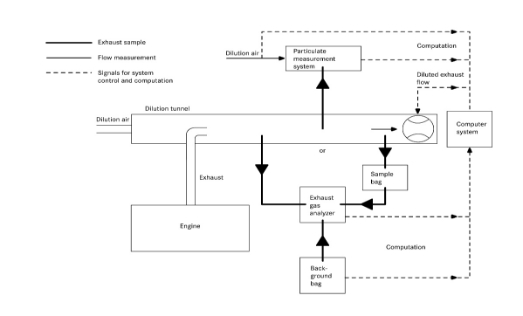
8.5.1. Determination of the diluted exhaust gas flow
8.5.1.1. Introduction
For calculation of the emissions in the diluted exhaust gas, it is necessary to know the diluted exhaust gas mass flow rate. The total diluted exhaust gas flow over the cycle (kg/test) shall be calculated from the measurement values over the cycle and the corresponding calibration data of the flow measurement device (V0 for PDP, KV for CFV, Cd for SSV) by one of the methods described in paragraphs 8.5.1.2. to 8.5.1.4. If the total sample flow of particulates (msep) exceeds 0.5 per cent of the total CVS flow (med), the CVS flow shall be corrected for msep or the particulate sample flow shall be returned to the CVS prior to the flow measuring device.
8.5.1.2. PDP-CVS system
The calculation of the mass flow over the cycle is as follows, if the temperature of the diluted exhaust is kept within ±6 K over the cycle by using a heat exchanger:
 (49)
(49)
Where:
V0 is the volume of gas pumped per revolution under test conditions, m³/rev
nP is the total revolutions of pump per test
pp is the absolute pressure at pump inlet, kPa
T is the average temperature of the diluted exhaust gas at pump inlet, K
If a system with flow compensation is used (i.e. without heat exchanger), the instantaneous mass emissions shall be calculated and integrated over the cycle. In this case, the instantaneous mass of the diluted exhaust gas shall be calculated as follows:
med,i = 1.293 x V0 x nP,i x pp x 273 / (101.3 x T) (50)
Where:
nP,i is the total revolutions of pump per time interval
8.5.1.3. CFV-CVS system
The calculation of the mass flow over the cycle is as follows, if the temperature of the diluted exhaust is kept within ±11 K over the cycle by using a heat exchanger:
med = 1.293 x t x Kv x pp / T 0.5 (51)
Where:
t is the cycle time, s
KV is the calibration coefficient of the critical flow venturi for standard conditions,
pp is the absolute pressure at venturi inlet, kPa
T is the absolute temperature at venturi inlet, K
If a system with flow compensation is used (i.e. without heat exchanger), the instantaneous mass emissions shall be calculated and integrated over the cycle. In this case, the instantaneous mass of the diluted exhaust gas shall be calculated as follows:
med,i = 1.293 x ti x KV x pp / T 0.5 (52)
Where:
ti is the time interval, s
8.5.1.4. SSV-CVS system
The calculation of the mass flow over the cycle shall be as follows, if the temperature of the diluted exhaust is kept within ±11 K over the cycle by using a heat exchanger:
med = 1.293 x QSSV (53)
With
 (54)
(54)
Where:
A0 is 0.005692 in SI units of 
dV is the diameter of the SSV throat, mm
Cd is the discharge coefficient of the SSV
pp is the absolute pressure at venturi inlet, kPa
T is the temperature at the venturi inlet, K
rp is the ratio of the SSV throat to inlet absolute static pressure, 
rD is the ratio of the SSV throat diameter, d, to the inlet pipe inner diameter D
If a system with flow compensation is used (i.e. without heat exchanger), the instantaneous mass emissions shall be calculated and integrated over the cycle. In this case, the instantaneous mass of the diluted exhaust gas shall be calculated as follows:
med = 1.293 x QSSV x ti (55)
Where:
ti is the time interval, s
The real time calculation shall be initialized with either a reasonable value for Cd, such as 0.98, or a reasonable value of Qssv. If the calculation is initialized with Qssv, the initial value of Qssv shall be used to evaluate the Reynolds number.
During all emissions tests, the Reynolds number at the SSV throat shall be in the range of Reynolds numbers used to derive the calibration curve developed in paragraph 9.5.4.
8.5.2. Determination of the gaseous components
8.5.2.1. Introduction
The gaseous components in the diluted exhaust gas emitted by the engine submitted for testing shall be measured by the methods described in Appendix 2 to this annex. Dilution of the exhaust shall be done with filtered ambient air, synthetic air or nitrogen. The flow capacity of the full flow system shall be large enough to completely eliminate water condensation in the dilution and sampling systems. Data evaluation and calculation procedures are described in paragraphs 8.5.2.2. and 8.5.2.3.
8.5.2.2. Data evaluation
The emission relevant data shall be recorded and stored in accordance with paragraph 7.6.6.
8.5.2.3. Calculation of mass emission
8.5.2.3.1. Systems with constant mass flow
For systems with heat exchanger, the mass of the pollutants shall be determined from the following equation:
mgas = ugas x cgas x med (in g/test) (56)
Where:
ugas is the respective value of the exhaust component from Table 6
cgas is the average background corrected concentration of the component, ppm
med is the total diluted exhaust mass over the cycle, kg
If measured on a dry basis, the dry/wet correction according to paragraph 8.1. shall be applied.
For the calculation of NOx, the mass emission shall be multiplied, if applicable, with the humidity correction factor kh,D, or kh,G, as determined according to paragraph 8.2.
The u values are given in Table 6. For calculating the ugas values, the density of the diluted exhaust gas has been assumed to be equal to air density. Therefore, the ugas values are identical for single gas components, but different for HC.
Table 6
Diluted exhaust gas u values and component densities
Fuel | de | | | Gas | | | |
NOx | CO | HC | CO2 | O2 | CH4 |
| | gas [kg/m3] | | | |
2.053 | 1.250 | a | 1.9636 | 1.4277 | 0.716 |
| | ugasb | | | |
Diesel (B7) | 1.293 | 0.001588 | 0.000967 | 0.000483 | 0.001519 | 0.001104 | 0.000553 |
Ethanol (ED95) | 1.293 | 0.001588 | 0.000967 | 0.000770 | 0.001519 | 0.001104 | 0.000553 |
CNGc | 1.293 | 0.001588 | 0.000967 | 0.000517d | 0.001519 | 0.001104 | 0.000553 |
Propane | 1.293 | 0.001588 | 0.000967 | 0.000507 | 0.001519 | 0.001104 | 0.000553 |
Butane | 1.293 | 0.001588 | 0.000967 | 0.000501 | 0.001519 | 0.001104 | 0.000553 |
LPGe | 1.293 | 0.001588 | 0.000967 | 0.000505 | 0.001519 | 0.001104 | 0.000553 |
Petrol (E10) | 1.293 | 0.001588 | 0.000967 | 0.000499 | 0.001519 | 0.001104 | 0.000554 |
Ethanol (E85) | 1.293 | 0.001588 | 0.000967 | 0.000722 | 0.001519 | 0.001104 | 0.000554 |
a depending on fuel b at = 2, dry air, 273 K, 101.3 kPa c u accurate within 0.2 % for mass composition of: C = 66 - 76 %; H = 22 - 25 %; N = 0 - 12 % d NMHC on the basis of CH2.93 (for total HC the ugas coefficient of CH4 shall be used) e u accurate within 0.2 % for mass composition of: C3 = 70 - 90 %; C4 = 10 - 30 % |
Alternatively, the u values may be calculated using the exact calculation method generally described in paragraph 8.4.2.4., as follows:
 (57)
(57)
Where:
Mgas is the molar mass of the gas component, g/mol (see Appendix 5 to this annex)
Me is the molar mass of the exhaust gas, g/mol
Md is the molar mass of the diluent = 28.965 g/mol
D is the dilution factor (see paragraph 8.5.2.3.2.)
8.5.2.3.2. Determination of the background corrected concentrations
The average background concentration of the gaseous pollutants in the diluent shall be subtracted from the measured concentrations to get the net concentrations of the pollutants. The average values of the background concentrations can be determined by the sample bag method or by continuous measurement with integration. The following equation shall be used:
cgas = cgas,e - cd x (1 - (1/D)) (58)
Where:
cgas,e is the concentration of the component measured in the diluted exhaust gas, ppm
cd is the concentration of the component measured in the diluent, ppm
D is the dilution factor
The dilution factor shall be calculated as follows:
a) For diesel fuelled engines and LPG fuelled gas engines
 (59)
(59)
b) For natural gas fuelled gas engines
 (60)
(60)
Where:
cCO2,e is the wet concentration of CO2 in the diluted exhaust gas, per cent vol
cHC,e is the wet concentration of HC in the diluted exhaust gas, ppm C1
cNMHC,e is the wet concentration of NMHC in the diluted exhaust gas, ppm C1
cCO,e is the wet concentration of CO in the diluted exhaust gas, ppm
FS is the stoichiometric factor
The stoichiometric factor shall be calculated as follows:
 (61)
(61)
Where:
is the molar hydrogen ratio of the fuel (H/C)
Alternatively, if the fuel composition is not known, the following stoichiometric factors may be used:
FS (diesel) = 13.4
FS (LPG) = 11.6
FS (NG) = 9.5
FS (E10) = 13.3
FS (E85) = 11.5
8.5.2.3.3. Systems with flow compensation
For systems without heat exchanger, the mass of the pollutants (g/test) shall be determined by calculating the instantaneous mass emissions and integrating the instantaneous values over the cycle. Also, the background correction shall be applied directly to the instantaneous concentration value. The following equation shall be applied:
 (62)
(62)
Where:
cgas,e is the concentration of the component measured in the diluted exhaust gas, ppm
cd is the concentration of the component measured in the diluent, ppm
med,i is the instantaneous mass of the diluted exhaust gas, kg
med is the total mass of diluted exhaust gas over the cycle, kg
ugas is the tabulated value from Table 6
D is the dilution factor
8.5.3. Particulate determination
8.5.3.1. Calculation of mass emission
The particulate mass (g/test) shall be calculated after buoyancy correction of the particulate sample filter according to paragraph 8.3., as follows:
 (63)
(63)
Where:
mp is the particulate mass sampled over the cycle, mg
msep is the mass of diluted exhaust gas passing the particulate collection filters, kg
med is the mass of diluted exhaust gas over the cycle, kg
With
msep = mset - mssd (64)
Where:
mset is the mass of double diluted exhaust gas through particulate filter, kg
mssd is the mass of secondary diluent, kg
If the particulate background level of the diluent is determined in accordance with paragraph 7.5.6., the particulate mass may be background corrected. In this case, the particulate mass (g/test) shall be calculated as follows:
 (65)
(65)
Where:
msep is the mass of diluted exhaust gas passing the particulate collection filters, kg
med is the mass of diluted exhaust gas over the cycle, kg
msd is the mass of diluent sampled by background particulate sampler, kg
mb is the mass of the collected background particulates of the diluent, mg
D is the dilution factor as determined in paragraph 8.5.2.3.2.
8.6. General calculations
8.6.1. Drift correction
With respect to drift verification in paragraph 7.8.4., the corrected concentration value shall be calculated as follows:
 (66)
(66)
Where:
cref,z is the reference concentration of the zero gas (usually zero), ppm
cref,s is the reference concentration of the span gas, ppm
cpre,z is the pre-test analyzer concentration of the zero gas, ppm
cpre,s is the pre-test analyzer concentration of the span gas, ppm
cpost,z is the post-test analyzer concentration of the zero gas, ppm
cpost,s is the post-test analyzer concentration of the span gas, ppm
cgas is the sample gas concentration, ppm
Two sets of specific emission results shall be calculated for each component in accordance with paragraph 8.6.3., after any other corrections have been applied. One set shall be calculated using uncorrected concentrations and another set shall be calculated using the concentrations corrected for drift according to equation 66.
Depending on the measurement system and calculation method used, the uncorrected emissions results shall be calculated with equations 36, 37, 56, 58 or 62, respectively. For calculation of the corrected emissions, cgas in equations 36, 37, 56, 58 or 62, respectively, shall be replaced with ccor of equation 66. If instantaneous concentration values cgas,i are used in the respective equation, the corrected value shall also be applied as instantaneous value ccor,i. In equations 58 and 62, the correction shall be applied to both the measured and the background concentration.
The comparison shall be made as a percentage of the uncorrected results. The difference between the uncorrected and the corrected brake-specific emission values shall be within ±4 per cent of the uncorrected brake-specific emission values or within ±4 per cent of the respective limit value, whichever is greater. If the drift is greater than 4 per cent, the test shall be voided.
If drift correction is applied, only the drift-corrected emission results shall be used when reporting emissions.
8.6.2. Calculation of NMHC and CH4
The calculation of NMHC and CH4 depends on the calibration method used. The FID for the measurement without NMC (lower path of Appendix 2 to this annex, Figure 11), shall be calibrated with propane. For the calibration of the FID in series with NMC (upper path of Appendix 2 to this annex, Figure 11), the following methods are permitted.
(a) Calibration gas – propane; propane bypasses NMC;
(b) Calibration gas – methane; methane passes through NMC.
The concentration of NMHC and CH4 shall be calculated as follows for (a):
 (67)
(67)
 (68)
(68)
The concentration of NMHC and CH4 shall be calculated as follows for (b):
 (67a)
(67a)
 (68a)
(68a)
Where:
cHC(w/NMC) is the HC concentration with sample gas flowing through the NMC, ppm
cHC(w/oNMC) is the HC concentration with sample gas bypassing the NMC, ppm
rh is the methane response factor as determined per paragraph 9.3.7.2.
EM is the methane efficiency as determined per paragraph 9.3.8.1.
EE is the ethane efficiency as determined per paragraph 9.3.8.2.
If rh < 1.05, it may be omitted in equations 67, 67a and 68a.
8.6.3. Calculation of the specific emissions
The specific emissions egas or ePM (g/kWh) shall be calculated for each individual component in the following ways depending on the type of test cycle.
For the WHSC, hot WHTC, or cold WHTC, the following equation shall be applied:
 (69)
(69)
Where:
m is the mass emission of the component, g/test
Wact is the actual cycle work as determined according to paragraph 7.8.6., kWh
For the WHTC, the final test result shall be a weighted average from cold start test and hot start test according to the following equation:
 (70)
(70)
Where:
mcold is the mass emission of the component on the cold start test, g/test
mhot is the mass emission of the component on the hot start test, g/test
Wact,cold is the actual cycle work on the cold start test, kWh
Wact,hot is the actual cycle work on the hot start test, kWh
If periodic regeneration in accordance with paragraph 6.6.2. applies, the regeneration adjustment factors kr,u or kr,d shall be multiplied with or be added to, respectively, the specific emissions result e as determined in equations 69 and 70.
9. Equipment specification and verification
This annex does not contain details of flow, pressure, and temperature measuring equipment or systems. Instead, only the linearity requirements of such equipment or systems necessary for conducting an emissions test are given in paragraph 9.2.
9.1. Dynamometer specification
An engine dynamometer with adequate characteristics to perform the appropriate test cycle described in paragraphs 7.2.1. and 7.2.2. shall be used.
The instrumentation for torque and speed measurement shall allow the measurement accuracy of the shaft power as needed to comply with the cycle validation criteria. Additional calculations may be necessary. The accuracy of the measuring equipment shall be such that the linearity requirements given in paragraph 9.2., Table 7 are not exceeded.
9.2. Linearity requirements
The calibration of all measuring instruments and systems shall be traceable to national (international) standards. The measuring instruments and systems shall comply with the linearity requirements given in Table 7. The linearity verification according to paragraph 9.2.1. shall be performed for the gas analyzers at least every three months or whenever a system repair or change is made that could influence calibration. For the other instruments and systems, the linearity verification shall be done as required by internal audit procedures, by the instrument manufacturer or in accordance with ISO 9000 requirements.
Table 7
Linearity requirements of instruments and measurement systems
Measurement system | min (a1 - 1)+ a0 | Slope
a1 | Standard error
SEE | Coefficient of determination
r2 |
Engine speed | ≤ 0.05 % max | 0.98 - 1.02 | ≤ 2 % max | ≥ 0.990 |
Engine torque | ≤ 1 % max | 0.98 - 1.02 | ≤ 2 % max | ≥ 0.990 |
Fuel flow | ≤ 1 % max | 0.98 - 1.02 | ≤ 2 % max | ≥ 0.990 |
Airflow | ≤ 1 % max | 0.98 - 1.02 | ≤ 2 % max | ≥ 0.990 |
Exhaust gas flow | ≤ 1 % max | 0.98 - 1.02 | ≤ 2 % max | ≥ 0.990 |
Diluent flow | ≤ 1 % max | 0.98 - 1.02 | ≤ 2 % max | ≥ 0.990 |
Diluted exhaust gas flow | ≤ 1 % max | 0.98 - 1.02 | ≤ 2 % max | ≥ 0.990 |
Sample flow | ≤ 1 % max | 0.98 - 1.02 | ≤ 2 % max | ≥ 0.990 |
Gas analyzers | ≤ 0.5 % max | 0.99 - 1.01 | ≤ 1 % max | ≥ 0.998 |
Gas dividers | ≤ 0.5 % max | 0.98 - 1.02 | ≤ 2 % max | ≥ 0.990 |
Temperatures | ≤ 1 % max | 0.99 - 1.01 | ≤ 1 % max | ≥ 0.998 |
Pressures | ≤ 1 % max | 0.99 - 1.01 | ≤ 1 % max | ≥ 0.998 |
PM balance | ≤ 1 % max | 0.99 - 1.01 | ≤ 1 % max | ≥ 0.998 |
9.2.1. Linearity verification
9.2.1.1. Introduction
A linearity verification shall be performed for each measurement system listed in Table 7. At least 10 reference values, or as specified otherwise, shall be introduced to the measurement system. For stand-alone pressure and temperature linearity verifications, at least three reference values shall be selected. The measured values shall be compared to the reference values by using a least squares linear regression in accordance with equation 11 in paragraph 7.8.7. The maximum limits in Table 7 refer to the maximum values expected during testing.
9.2.1.2. General requirements
The measurement systems shall be warmed up according to the recommendations of the instrument manufacturer. The measurement systems shall be operated at their specified temperatures, pressures and flows.
9.2.1.3. Procedure
The linearity verification shall be run for each normally used operating range with the following steps:
(a) The instrument shall be set at zero by introducing a zero signal. For gas analyzers, purified synthetic air (or nitrogen) shall be introduced directly to the analyzer port;
(b) The instrument shall be spanned by introducing a span signal. For gas analyzers, an appropriate span gas shall be introduced directly to the analyzer port;
(c) The zero procedure of (a) shall be repeated;
(d) The verification shall be established by introducing at least 10 reference values (including zero) that are within the range from zero to the highest values expected during emission testing. For gas analyzers, known gas concentrations in accordance with paragraph 9.3.3.2. shall be introduced directly to the analyzer port;
(e) At a recording frequency of at least 1 Hz, the reference values shall be measured and the measured values recorded for 30 seconds;
(f) The arithmetic mean values over the 30 seconds period shall be used to calculate the least squares linear regression parameters according to equation 11 in paragraph 7.8.7;
(g) The linear regression parameters shall meet the requirements of paragraph 9.2., Table 7;
(h) The zero setting shall be rechecked and the verification procedure repeated, if necessary.
9.3. Gaseous emissions measurement and sampling system
9.3.1. Analyzer specifications
9.3.1.1. General
The analyzers shall have a measuring range and response time appropriate for the accuracy required to measure the concentrations of the exhaust gas components under transient and steady state conditions.
The electromagnetic compatibility (EMC) of the equipment shall be on a level as to minimize additional errors.
9.3.1.2. Accuracy
The accuracy, defined as the deviation of the analyzer reading from the reference value, shall not exceed ±2 per cent of the reading or ±0.3 per cent of full scale whichever is larger.
9.3.1.3. Precision
The precision, defined as 2.5 times the standard deviation of 10 repetitive responses to a given calibration or span gas, shall be no greater than 1 per cent of full scale concentration for each range used above 155 ppm (or ppm C) or 2 per cent of each range used below 155 ppm (or ppm C).
9.3.1.4. Noise
The analyzer peak-to-peak response to zero and calibration or span gases over any 10 seconds period shall not exceed 2 per cent of full scale on all ranges used.
9.3.1.5. Zero drift
The drift of the zero response shall be specified by the instrument manufacturer.
9.3.1.6. Span drift
The drift of the span response shall be specified by the instrument manufacturer.
9.3.1.7. Rise time
The rise time of the analyzer installed in the measurement system shall not exceed 2.5 seconds.
9.3.1.8. Gas drying
Exhaust gases may be measured wet or dry. A gas-drying device, if used, shall have a minimal effect on the composition of the measured gases. Chemical dryers are not an acceptable method of removing water from the sample.
9.3.2. Gas analyzers
9.3.2.1. Introduction
Paragraphs 9.3.2.2. to 9.2.3.7. describe the measurement principles to be used. A detailed description of the measurement systems is given in Appendix 2 to this annex. The gases to be measured shall be analyzed with the following instruments. For non-linear analyzers, the use of linearizing circuits is permitted.
9.3.2.2. Carbon monoxide (CO) analysis
The carbon monoxide analyzer shall be of the non-dispersive infrared (NDIR) absorption type.
9.3.2.3. Carbon dioxide (CO2) analysis
The carbon dioxide analyzer shall be of the non-dispersive infrared (NDIR) absorption type.
9.3.2.4. Hydrocarbon (HC) analysis
The hydrocarbon analyzer shall be of the heated flame ionization detector (HFID) type with detector, valves, pipework, etc. heated so as to maintain a gas temperature of 463 K ± 10 K (190 ± 10 °C). Optionally, for natural gas fuelled and PI engines, the hydrocarbon analyzer may be of the non-heated flame ionization detector (FID) type depending upon the method used (see Appendix 2 to this annex, paragraph A.2.1.3.).
9.3.2.5. Methane (CH4) and non-methane hydrocarbon (NMHC) analysis
The determination of the methane and non-methane hydrocarbon fraction shall be performed with a heated non-methane cutter (NMC) and two FIDs as per Appendix 2 to this annex, paragraph A.2.1.4. and paragraph A.2.1.5. The concentration of the components shall be determined as per paragraph 8.6.2.
9.3.2.6. Oxides of nitrogen (NOx) analysis
Two measurement instruments are specified for NOx measurement and either instrument may be used provided it meets the criteria specified in paragraphs 9.3.2.6.1. or 9.3.2.6.2., respectively. For the determination of system equivalency of an alternate measurement procedure in accordance with paragraph 5.1.1., only the CLD is permitted.
9.3.2.6.1. Chemiluminescent detector (CLD)
If measured on a dry basis, the oxides of nitrogen analyzer shall be of the chemiluminescent detector (CLD) or heated chemiluminescent detector (HCLD) type with a NO2/NO converter. If measured on a wet basis, a HCLD with converter maintained above 328 K (55 °C) shall be used, provided the water quench check (see paragraph 9.3.9.2.2.) is satisfied. For both CLD and HCLD, the sampling path shall be maintained at a wall temperature of 328 K to 473 K (55 °C to 200 °C) up to the converter for dry measurement and up to the analyzer for wet measurement.
9.3.2.6.2. Non-dispersive ultraviolet detector (NDUV)
A non-dispersive ultraviolet (NDUV) analyzer shall be used to measure NOx concentration. If the NDUV analyzer measures only NO, a NO2/NO converter shall be placed upstream of the NDUV analyzer. The NDUV temperature shall be maintained to prevent aqueous condensation, unless a sample dryer is installed upstream of the NO2/NO converter, if used, or upstream of the analyzer.
9.3.2.7. Air to fuel measurement
The air to fuel measurement equipment used to determine the exhaust gas flow as specified in paragraph 8.4.1.6. shall be a wide range air to fuel ratio sensor or lambda sensor of Zirconia type. The sensor shall be mounted directly on the exhaust pipe where the exhaust gas temperature is high enough to eliminate water condensation.
The accuracy of the sensor with incorporated electronics shall be within:
3 per cent of reading for < 2
5 per cent of reading for 2 < 5
10 per cent of reading for 5
To fulfil the accuracy specified above, the sensor shall be calibrated as specified by the instrument manufacturer.
9.3.3. Gases
The shelf life of all gases shall be respected.
9.3.3.1. Pure gases
The required purity of the gases is defined by the contamination limits given below. The following gases shall be available for operation:
a) For raw exhaust gas
Purified nitrogen
(Contamination 1 ppm C1, 1 ppm CO, 400 ppm CO2,
0.1 ppm NO)
Purified oxygen
(Purity 99.5 per cent vol O2)
Hydrogen-helium mixture (FID burner fuel)
(40 ± 1 per cent hydrogen, balance helium)
(Contamination 1 ppm C1, 400 ppm CO2)
Purified synthetic air
(Contamination 1 ppm C1, 1 ppm CO, 400 ppm CO2,
0.1 ppm NO)
(Oxygen content between 18-21 per cent vol.)
b) For dilute exhaust gas (optionally for raw exhaust gas)
Purified nitrogen
(Contamination 0.05 ppm C1, 1 ppm CO, 10 ppm CO2,
0.02 ppm NO)
Purified oxygen
(Purity 99.5 per cent vol O2)
Hydrogen-helium mixture (FID burner fuel)
(40 ± 1 per cent hydrogen, balance helium)
(Contamination 0.05 ppm C1, 10 ppm CO2)
Purified synthetic air
(Contamination 0.05 ppm C1, 1 ppm CO, 10 ppm CO2,
0.02 ppm NO)
(Oxygen content between 20.5 - 21.5 per cent vol.)
If gas bottles are not available, a gas purifier may be used, if contamination levels can be demonstrated.
9.3.3.2. Calibration and span gases
Mixtures of gases having the following chemical compositions shall be available, if applicable. Other gas combinations are allowed provided the gases do not react with one another. The expiration date of the calibration gases stated by the manufacturer shall be recorded.
C3H8 and purified synthetic air (see paragraph 9.3.3.1.);
CO and purified nitrogen;
NO and purified nitrogen;
NO2 and purified synthetic air;
CO2 and purified nitrogen;
CH4 and purified synthetic air;
C2H6 and purified synthetic air.
The true concentration of a calibration and span gas shall be within ±1 per cent of the nominal value, and shall be traceable to national or international standards. All concentrations of calibration gas shall be given on a volume basis (volume per cent or volume ppm).
9.3.3.3. Gas dividers
The gases used for calibration and span may also be obtained by means of gas dividers (precision blending devices), diluting with purified N2 or with purified synthetic air. The accuracy of the gas divider shall be such that the concentration of the blended calibration gases is accurate to within ±2 per cent. This accuracy implies that primary gases used for blending shall be known to an accuracy of at least 1 per cent, traceable to national or international gas standards. The verification shall be performed at between 15 and 50 per cent of full scale for each calibration incorporating a gas divider. An additional verification may be performed using another calibration gas, if the first verification has failed.
Optionally, the blending device may be checked with an instrument which by nature is linear, e.g. using NO gas with a CLD. The span value of the instrument shall be adjusted with the span gas directly connected to the instrument. The gas divider shall be checked at the settings used and the nominal value shall be compared to the measured concentration of the instrument. This difference shall in each point be within ±1 per cent of the nominal value.
For conducting the linearity verification according to paragraph 9.2.1., the gas divider shall be accurate to within 1 per cent.
9.3.3.4. Oxygen interference check gases
Oxygen interference check gases are a blend of propane, oxygen and nitrogen. They shall contain propane with 350 ppm C 75 ppm C hydrocarbon. The concentration value shall be determined to calibration gas tolerances by chromatographic analysis of total hydrocarbons plus impurities or by dynamic blending. The oxygen concentrations required for positive ignition and compression ignition engine testing are listed in Table 8 with the remainder being purified nitrogen.
Table 8
Oxygen interference check gases
Type of engine | O2 concentration (per cent) |
Compression ignition | 21 (20 to 22) |
Compression and positive ignition | 10 (9 to 11) |
Compression and positive ignition | 5 (4 to 6) |
Positive ignition | 0 (0 to 1) |
9.3.4. Leak check
A system leak check shall be performed. The probe shall be disconnected from the exhaust system and the end plugged. The analyzer pump shall be switched on. After an initial stabilization period all flowmeters will read approximately zero in the absence of a leak. If not, the sampling lines shall be checked and the fault corrected.
The maximum allowable leakage rate on the vacuum side shall be 0.5 per cent of the in-use flow rate for the portion of the system being checked. The analyzer flows and bypass flows may be used to estimate the in-use flow rates.
Alternatively, the system may be evacuated to a pressure of at least 20 kPa vacuum (80 kPa absolute). After an initial stabilization period the pressure increase p (kPa/min) in the system shall not exceed:
p = p / Vs 0.005 qvs (71)
Where:
Vs is the system volume, l
qvs is the system flow rate, l/min
Another method is the introduction of a concentration step change at the beginning of the sampling line by switching from zero to span gas. If for a correctly calibrated analyzer after an adequate period of time the reading is ≤ 99 per cent compared to the introduced concentration, this points to a leakage problem that shall be corrected.
9.3.5. Response time check of the analytical system
The system settings for the response time evaluation shall be exactly the same as during measurement of the test run (i.e. pressure, flow rates, filter settings on the analyzers and all other response time influences). The response time determination shall be done with gas switching directly at the inlet of the sample probe. The gas switching shall be done in less than 0.1 second. The gases used for the test shall cause a concentration change of at least 60 per cent full scale (FS).
The concentration trace of each single gas component shall be recorded. The response time is defined to be the difference in time between the gas switching and the appropriate change of the recorded concentration. The system response time (t90) consists of the delay time to the measuring detector and the rise time of the detector. The delay time is defined as the time from the change (t0) until the response is 10 per cent of the final reading (t10). The rise time is defined as the time between 10 per cent and 90 per cent response of the final reading (t90 – t10).
For time alignment of the analyzer and exhaust flow signals, the transformation time is defined as the time from the change (t0) until the response is 50 per cent of the final reading (t50).
The system response time shall be 10 s with a rise time of 2.5 seconds in accordance with paragraph 9.3.1.7. for all limited components (CO, NOx, HC or NMHC) and all ranges used. When using a NMC for the measurement of NMHC, the system response time may exceed 10 seconds.
9.3.6. Efficiency test of NOx converter
The efficiency of the converter used for the conversion of NO2 into NO is tested as given in paragraphs 9.3.6.1. to 9.3.6.8. (see Figure 8).
Figure 8
Scheme of NO2 converter efficiency device

9.3.6.1. Test setup
Using the test setup as schematically shown in Figure 8 and the procedure below, the efficiency of the converter shall be tested by means of an ozonator.
9.3.6.2. Calibration
The CLD and the HCLD shall be calibrated in the most common operating range following the manufacturer's specifications using zero and span gas (the NO content of which shall amount to about 80 per cent of the operating range and the NO2 concentration of the gas mixture to less than 5 per cent of the NO concentration). The NOx analyzer shall be in the NO mode so that the span gas does not pass through the converter. The indicated concentration has to be recorded.
9.3.6.3. Calculation
The per cent efficiency of the converter shall be calculated as follows:
 (72)
(72)
Where:
a is the NOx concentration according to paragraph 9.3.6.6.
b is the NOx concentration according to paragraph 9.3.6.7.
c is the NO concentration according to paragraph 9.3.6.4.
d is the NO concentration according to paragraph 9.3.6.5.
9.3.6.4. Adding of oxygen
Via a T-fitting, oxygen or zero air shall be added continuously to the gas flow until the concentration indicated is about 20 per cent less than the indicated calibration concentration given in paragraph 9.3.6.2. (the analyzer is in the NO mode).
The indicated concentration (c) shall be recorded. The ozonator is kept deactivated throughout the process.
9.3.6.5. Activation of the ozonator
The ozonator shall be activated to generate enough ozone to bring the NO concentration down to about 20 per cent (minimum 10 per cent) of the calibration concentration given in paragraph 9.3.6.2. The indicated concentration (d) shall be recorded (the analyzer is in the NO mode).
9.3.6.6. NOx mode
The NO analyzer shall be switched to the NOx mode so that the gas mixture (consisting of NO, NO2, O2 and N2) now passes through the converter. The indicated concentration (a) shall be recorded (the analyzer is in the NOx mode).
9.3.6.7. Deactivation of the ozonator
The ozonator is now deactivated. The mixture of gases described in paragraph 9.3.6.6. passes through the converter into the detector. The indicated concentration (b) shall be recorded (the analyzer is in the NOx mode).
9.3.6.8. NO mode
Switched to NO mode with the ozonator deactivated, the flow of oxygen or synthetic air shall be shut off. The NOx reading of the analyzer shall not deviate by more than ±5 per cent from the value measured according to paragraph 9.3.6.2. (the analyzer is in the NO mode).
9.3.6.9. Test interval
The efficiency of the converter shall be tested at least once per month.
9.3.6.10. Efficiency requirement
The efficiency of the converter ENOx shall not be less than 95 per cent.
If, with the analyzer in the most common range, the ozonator cannot give a reduction from 80 per cent to 20 per cent according to paragraph 9.3.6.5., the highest range which will give the reduction shall be used.
9.3.7. Adjustment of the FID
9.3.7.1. Optimization of the detector response
The FID shall be adjusted as specified by the instrument manufacturer. A propane in air span gas shall be used to optimize the response on the most common operating range.
With the fuel and airflow rates set at the manufacturer's recommendations, a 350 ± 75 ppm C span gas shall be introduced to the analyzer. The response at a given fuel flow shall be determined from the difference between the span gas response and the zero gas response. The fuel flow shall be incrementally adjusted above and below the manufacturer's specification. The span and zero response at these fuel flows shall be recorded. The difference between the span and zero response shall be plotted and the fuel flow adjusted to the rich side of the curve. This is the initial flow rate setting which may need further optimization depending on the results of the hydrocarbon response factors and the oxygen interference check according to paragraphs 9.3.7.2. and 9.3.7.3. If the oxygen interference or the hydrocarbon response factors do not meet the following specifications, the airflow shall be incrementally adjusted above and below the manufacturer's specifications, repeating paragraphs 9.3.7.2. and 9.3.7.3. for each flow.
The optimization may optionally be conducted using the procedures outlined in SAE paper No. 770141.
9.3.7.2. Hydrocarbon response factors
A linearity verification of the analyzer shall be performed using propane in air and purified synthetic air according to paragraph 9.2.1.3.
Response factors shall be determined when introducing an analyzer into service and after major service intervals. The response factor (rh) for a particular hydrocarbon species is the ratio of the FID C1 reading to the gas concentration in the cylinder expressed by ppm C1.
The concentration of the test gas shall be at a level to give a response of approximately 80 per cent of full scale. The concentration shall be known to an accuracy of ±2 per cent in reference to a gravimetric standard expressed in volume. In addition, the gas cylinder shall be preconditioned for 24 hours at a temperature of 298 K ± 5 K (25 °C ± 5 °C).
The test gases to be used and the relative response factor ranges are as follows:
(a) Methane and purified synthetic air 1.00 rh 1.15;
(b) Propylene and purified synthetic air 0.90 rh 1.1;
(c) Toluene and purified synthetic air 0.90 rh 1.1.
These values are relative to a rh of 1 for propane and purified synthetic air.
9.3.7.3. Oxygen interference check
For raw exhaust gas analyzers only, the oxygen interference check shall be performed when introducing an analyzer into service and after major service intervals.
A measuring range shall be chosen where the oxygen interference check gases will fall in the upper 50 per cent. The test shall be conducted with the oven temperature set as required. Oxygen interference check gas specifications are found in paragraph 9.3.3.4.
(a) The analyzer shall be set at zero;
(b) The analyzer shall be spanned with the 0 per cent oxygen blend for positive ignition engines. Compression ignition engine instruments shall be spanned with the 21 per cent oxygen blend;
(c) The zero response shall be rechecked. If it has changed by more than 0.5 per cent of full scale, steps (a) and (b) of this paragraph shall be repeated;
(d) The 5 per cent and 10 per cent oxygen interference check gases shall be introduced;
(e) The zero response shall be rechecked. If it has changed by more than 1 per cent of full scale, the test shall be repeated;
(f) The oxygen interference EO2 shall be calculated for each mixture in step (d) as follows:
EO2 = (cref,d - c) 100 / cref,d (73)
With the analyzer response being
 (74)
(74)
Where:
cref,b is the reference HC concentration in step (b), ppm C
cref,d is the reference HC concentration in step (d), ppm C
cFS,b is the full scale HC concentration in step (b), ppm C
cFS,d is the full scale HC concentration in step (d), ppm C
cm,b is the measured HC concentration in step (b), ppm C
cm,d is the measured HC concentration in step (d), ppm C
(g) The oxygen interference EO2 shall be less than 1.5 per cent for all required oxygen interference check gases prior to testing;
(h) If the oxygen interference EO2 is greater than 1.5 per cent, corrective action may be taken by incrementally adjusting the airflow above and below the manufacturer's specifications, the fuel flow and the sample flow;
(i) The oxygen interference shall be repeated for each new setting.
9.3.8. Efficiency of the non-methane cutter (NMC)
The NMC is used for the removal of the non-methane hydrocarbons from the sample gas by oxidizing all hydrocarbons except methane. Ideally, the conversion for methane is 0 per cent, and for the other hydrocarbons represented by ethane is 100 per cent. For the accurate measurement of NMHC, the two efficiencies shall be determined and used for the calculation of the NMHC emission mass flow rate (see paragraph 8.6.2.).
9.3.8.1. Methane Efficiency
Methane calibration gas shall be flown through the FID with and without bypassing the NMC and the two concentrations recorded. The efficiency shall be determined as follows:
 (75)
(75)
Where:
cHC(w/NMC) is the HC concentration with CH4 flowing through the NMC, ppm C
cHC(w/o NMC) is the HC concentration with CH4 bypassing the NMC, ppm C
9.3.8.2. Ethane Efficiency
Ethane calibration gas shall be flown through the FID with and without bypassing the NMC and the two concentrations recorded. The efficiency shall be determined as follows:
 (76)
(76)
Where:
cHC(w/NMC) is the HC concentration with C2H6 flowing through the NMC, ppm C
cHC(w/o NMC) is the HC concentration with C2H6 bypassing the NMC, ppm C
9.3.9. Interference effects
Other gases than the one being analyzed can interfere with the reading in several ways. Positive interference occurs in NDIR instruments where the interfering gas gives the same effect as the gas being measured, but to a lesser degree. Negative interference occurs in NDIR instruments by the interfering gas broadening the absorption band of the measured gas, and in CLD instruments by the interfering gas quenching the reaction. The interference checks in paragraphs 9.3.9.1. and 9.3.9.3. shall be performed prior to an analyzer's initial use and after major service intervals.
9.3.9.1. CO analyzer interference check
Water and CO2 can interfere with the CO analyzer performance. Therefore, a CO2 span gas having a concentration of 80 to 100 per cent of full scale of the maximum operating range used during testing shall be bubbled through water at room temperature and the analyzer response recorded. The analyzer response shall not be more than 2 per cent of the mean CO concentration expected during testing.
Interference procedures for CO2 and H2O may also be run separately. If the CO2 and H2O levels used are higher than the maximum levels expected during testing, each observed interference value shall be scaled down by multiplying the observed interference by the ratio of the maximum expected concentration value to the actual value used during this procedure. Separate interference procedures concentrations of H2O that are lower than the maximum levels expected during testing may be run, but the observed H2O interference shall be scaled up by multiplying the observed interference by the ratio of the maximum expected H2O concentration value to the actual value used during this procedure. The sum of the two scaled interference values shall meet the tolerance specified in this paragraph.
9.3.9.2. NOx analyzer quench checks for CLD analyzer
The two gases of concern for CLD (and HCLD) analyzers are CO2 and water vapour. Quench responses to these gases are proportional to their concentrations, and therefore require test techniques to determine the quench at the highest expected concentrations experienced during testing. If the CLD analyzer uses quench compensation algorithms that utilize H2O and/or CO2 measurement instruments, quench shall be evaluated with these instruments active and with the compensation algorithms applied.
9.3.9.2.1. CO2 quench check
A CO2 span gas having a concentration of 80 to 100 per cent of full scale of the maximum operating range shall be passed through the NDIR analyzer and the CO2 value recorded as A. It shall then be diluted approximately 50 per cent with NO span gas and passed through the NDIR and CLD, with the CO2 and NO values recorded as B and C, respectively. The CO2 shall then be shut off and only the NO span gas be passed through the (H)CLD and the NO value recorded as D.
The per cent quench shall be calculated as follows:
 (77)
(77)
Where:
A is the undiluted CO2 concentration measured with NDIR, per cent
B is the diluted CO2 concentration measured with NDIR, per cent
C is the diluted NO concentration measured with (H)CLD, ppm
D is the undiluted NO concentration measured with (H)CLD, ppm
Alternative methods of diluting and quantifying of CO2 and NO span gas values such as dynamic mixing/blending are permitted with the approval of the Type Approval Authority.
9.3.9.2.2. Water quench check
This check applies to wet gas concentration measurements only. Calculation of water quench shall consider dilution of the NO span gas with water vapour and scaling of water vapour concentration of the mixture to that expected during testing.
A NO span gas having a concentration of 80 per cent to 100 per cent of full scale of the normal operating range shall be passed through the (H)CLD and the NO value recorded as D. The NO span gas shall then be bubbled through water at room temperature and passed through the (H)CLD and the NO value recorded as C. The water temperature shall be determined and recorded as F. The mixture's saturation vapour pressure that corresponds to the bubbler water temperature (F) shall be determined and recorded as G.
The water vapour concentration (in per cent) of the mixture shall be calculated as follows:
H = 100 x (G / pb) (78)
and recorded as H. The expected diluted NO span gas (in water vapour) concentration shall be calculated as follows:
De = D x ( 1- H / 100 ) (79)
and recorded as De. The maximum exhaust water vapour concentration (in per cent) expected during testing shall be estimated from the maximum CO2 concentration in the exhaust gas A as follows:
Hm = α/2 x A (80)
and recorded as Hm
The per cent water quench shall be calculated as follows:
EH2O = 100 x ( ( De - C ) / De) x (Hm / H) (81)
Where:
De is the expected diluted NO concentration, ppm
C is the measured diluted NO concentration, ppm
Hm is the maximum water vapour concentration, per cent
H is the actual water vapour concentration, per cent
9.3.9.2.3. Maximum allowable quench
The combined CO2 and water quench shall not exceed 2 per cent of full scale.
9.3.9.3. NOx analyzer quench check for NDUV analyzer
Hydrocarbons and H2O can positively interfere with a NDUV analyzer by causing a response similar to NOx. If the NDUV analyzer uses compensation algorithms that utilize measurements of other gases to meet this interference verification, simultaneously such measurements shall be conducted to test the algorithms during the analyzer interference verification.
9.3.9.3.1. Procedure
The NDUV analyzer shall be started, operated, zeroed, and spanned according to the instrument manufacturer's instructions. It is recommended to extract engine exhaust to perform this verification. A CLD shall be used to quantify NOx in the exhaust. The CLD response shall be used as the reference value. Also HC shall be measured in the exhaust with a FID analyzer. The FID response shall be used as the reference hydrocarbon value.
Upstream of any sample dryer, if used during testing, the engine exhaust shall be introduced into the NDUV analyzer. Time shall be allowed for the analyzer response to stabilize. Stabilization time may include time to purge the transfer line and to account for analyzer response. While all analyzers measure the sample's concentration, 30 seconds of sampled data shall be recorded, and the arithmetic means for the three analyzers calculated.
The CLD mean value shall be subtracted from the NDUV mean value. This difference shall be multiplied by the ratio of the expected mean HC concentration to the HC concentration measured during the verification, as follows:
 (82)
(82)
Where:
cNOx,CLD is the measured NOx concentration with CLD, ppm
cNOx,NDUV is the measured NOx concentration with NDUV, ppm
cHC,e is the expected max. HC concentration, ppm
cHC,m is the measured HC concentration, ppm
9.3.9.3.2. Maximum allowable quench
The combined HC and water quench shall not exceed 2 per cent of the NOx concentration expected during testing.
9.3.9.4. Sample dryer
A sample dryer removes water, which can otherwise interfere with a NOx measurement.
9.3.9.4.1. Sample dryer efficiency
For dry CLD analysers, it shall be demonstrated that for the highest expected water vapour concentration Hm (see paragraph 9.3.9.2.2.), the sample dryer maintains CLD humidity at ≤ 5 g water/kg dry air (or about 0.8 volume per cent H2O), which is 100 per cent relative humidity at 3.9 °C and 101.3 kPa. This humidity specification is also equivalent to about 25 per cent relative humidity at 25 °C and 101.3 kPa. This may be demonstrated by measuring the temperature at the outlet of a thermal dehumidifier, or by measuring humidity at a point just upstream of the CLD. Humidity of the CLD exhaust might also be measured as long as the only flow into the CLD is the flow from the dehumidifier.
9.3.9.4.2. Sample dryer NO2 penetration
Liquid water remaining in an improperly designed sample dryer can remove NO2 from the sample. If a sample dryer is used in combination with an NDUV analyzer without an NO2/NO converter upstream, it could therefore remove NO2 from the sample prior NOx measurement.
The sample dryer shall allow for measuring at least 95 per cent of the total NO2 at the maximum expected concentration of NO2.
9.3.10. Sampling for raw gaseous emissions, if applicable
The gaseous emissions sampling probes shall be fitted at least 0.5 m or three times the diameter of the exhaust pipe - whichever is the larger - upstream of the exit of the exhaust gas system but sufficiently close to the engine as to ensure an exhaust gas temperature of at least 343 K (70 °C) at the probe.
In the case of a multi-cylinder engine with a branched exhaust manifold, the inlet of the probe shall be located sufficiently far downstream so as to ensure that the sample is representative of the average exhaust emissions from all cylinders. In multi-cylinder engines having distinct groups of manifolds, such as in a "Vee" engine configuration, it is recommended to combine the manifolds upstream of the sampling probe. If this is not practical, it is permissible to acquire a sample from the group with the highest CO2 emission. For exhaust emission calculation the total exhaust mass flow shall be used.
If the engine is equipped with an exhaust after-treatment system, the exhaust sample shall be taken downstream of the exhaust after-treatment system.
9.3.11. Sampling for dilute gaseous emissions, if applicable
The exhaust pipe between the engine and the full flow dilution system shall conform to the requirements laid down in Appendix 2 to this annex. The gaseous emissions sample probe(s) shall be installed in the dilution tunnel at a point where the diluent and exhaust gas are well mixed, and in close proximity to the particulates sampling probe.
Sampling can generally be done in two ways:
(a) The emissions are sampled into a sampling bag over the cycle and measured after completion of the test; for HC, the sample bag shall be heated to 464 11 K (191 11°C), for NOx, the sample bag temperature shall be above the dew point temperature;
(b) The emissions are sampled continuously and integrated over the cycle.
The background concentration shall be determined upstream of the dilution tunnel according to (a) or (b), and shall be subtracted from the emissions concentration according to paragraph 8.5.2.3.2.
9.4. Particulate measurement and sampling system
9.4.1. General specifications
To determine the mass of the particulates, a particulate dilution and sampling system, a particulate sampling filter, a microgram balance, and a temperature and humidity controlled weighing chamber, are required. The particulate sampling system shall be designed to ensure a representative sample of the particulates proportional to the exhaust flow.
9.4.2. General requirements of the dilution system
The determination of the particulates requires dilution of the sample with filtered ambient air, synthetic air or nitrogen (the diluent). The dilution system shall be set as follows:
(a) Completely eliminate water condensation in the dilution and sampling systems;
(b) Maintain the temperature of the diluted exhaust gas between 315 K (42 °C) and 325 K (52 °C) within 20 cm upstream or downstream of the filter holder(s);
(c) The diluent temperature shall be between 293 K and 325 K (20 °C to 52 °C) in close proximity to the entrance into the dilution tunnel;
(d) The minimum dilution ratio shall be within the range of 5:1 to 7:1 and at least 2:1 for the primary dilution stage based on the maximum engine exhaust flow rate;
(e) For a partial flow dilution system, the residence time in the system from the point of diluent introduction to the filter holder(s) shall be between 0.5 and 5 seconds;
(f) For a full flow dilution system, the overall residence time in the system from the point of diluent introduction to the filter holder(s) shall be between 1 and 5 seconds, and the residence time in the secondary dilution system, if used, from the point of secondary diluent introduction to the filter holder(s) shall be at least 0.5 seconds.
Dehumidifying the diluent before entering the dilution system is permitted, and especially useful if diluent humidity is high.
9.4.3. Particulate sampling
9.4.3.1. Partial flow dilution system
The particulate sampling probe shall be installed in close proximity to the gaseous emissions sampling probe, but sufficiently distant as to not cause interference. Therefore, the installation provisions of paragraph 9.3.10. also apply to particulate sampling. The sampling line shall conform to the requirements laid down in Appendix 2 to this annex.
In the case of a multi-cylinder engine with a branched exhaust manifold, the inlet of the probe shall be located sufficiently far downstream so as to ensure that the sample is representative of the average exhaust emissions from all cylinders. In multi-cylinder engines having distinct groups of manifolds, such as in a "Vee" engine configuration, it is recommended to combine the manifolds upstream of the sampling probe. If this is not practical, it is permissible to acquire a sample from the group with the highest particulate emission. For exhaust emission calculation the total exhaust mass flow of the manifold shall be used.
9.4.3.2. Full flow dilution system
The particulate sampling probe shall be installed in close proximity to the gaseous emissions sampling probe, but sufficiently distant as to not cause interference, in the dilution tunnel. Therefore, the installation provisions of paragraph 9.3.11. also apply to particulate sampling. The sampling line shall conform to the requirements laid down in Appendix 2 to this annex.
9.4.4. Particulate sampling filters
The diluted exhaust shall be sampled by a filter that meets the requirements of paragraphs 9.4.4.1. to 9.4.4.3. during the test sequence.
9.4.4.1. Filter specification
All filter types shall have a 0.3 μm DOP (di-octylphthalate) or PAO (poly-alpha-olefin) collection efficiency of at least 99 per cent. The sample filter manufacturer’s measurements reflected in their product ratings may be used to show this requirement. The filter material shall be either:
(a) Fluorocarbon (PTFE) coated glass fibre, or
(b) Fluorocarbon (PTFE) membrane.
9.4.4.2. Filter size
The filter shall be circular with a nominal diameter of 47 mm (tolerance of 46.50 0.6 mm) and an exposed diameter (filter stain diameter) of at least 38 mm.
9.4.4.3. Filter face velocity
The face velocity through the filter shall be between 0.90 and 1.00 m/s with less than 5 per cent of the recorded flow values exceeding this range. If the total PM mass on the filter exceeds 400 µg, the filter face velocity may be reduced to 0.50 m/s. The face velocity shall be calculated as the volumetric flow rate of the sample at the pressure upstream of the filter and temperature of the filter face, divided by the filter's exposed area.
9.4.5. Weighing chamber and analytical balance specifications
The chamber (or room) environment shall be free of any ambient contaminants (such as dust, aerosol, or semi-volatile material) that could contaminate the particulate filters. The weighing room shall meet the required specifications for at least 60 min before weighing filters.
9.4.5.1. Weighing chamber conditions
The temperature of the chamber (or room) in which the particulate filters are conditioned and weighed shall be maintained to within 295 K ± 1 K
(22 °C ± 1 °C) during all filter conditioning and weighing. The humidity shall be maintained to a dew point of 282.5 K ± 1 K (9.5 °C ± 1 °C).
If the stabilization and weighing environments are separate, the temperature of the stabilization environment shall be maintained at a tolerance of
295 K ± 3 K (22 °C ± 3 °C), but the dew point requirement remains at 282.5 K ± 1 K (9.5 °C ± 1 °C).
Humidity and ambient temperature shall be recorded.
9.4.5.2. Reference filter weighing
At least two unused reference filters shall be weighed within 12 hours of, but preferably at the same time as the sample filter weighing. They shall be the same material as the sample filters. Buoyancy correction shall be applied to the weighings.
If the weight of any of the reference filters changes between sample filter weighings by more than 10 µg, all sample filters shall be discarded and the emissions test repeated.
The reference filters shall be periodically replaced based on good engineering judgement, but at least once per year.
9.4.5.3. Analytical balance
The analytical balance used to determine the filter weight shall meet the linearity verification criterion of paragraph 9.2., Table 7. This implies a precision (standard deviation) of at least 2 µg and a resolution of at least 1 µg (1 digit = 1 µg).
In order to ensure accurate filter weighing, it is recommended that the balance be installed as follows:
(a) Installed on a vibration-isolation platform to isolate it from external noise and vibration;
(b) Shielded from convective airflow with a static-dissipating draft shield that is electrically grounded.
9.4.5.4. Elimination of static electricity effects
The filter shall be neutralized prior to weighing, e.g. by a Polonium neutralizer or a device of similar effect. If a PTFE membrane filter is used, the static electricity shall be measured and is recommended to be within
2.0 V of neutral.
Static electric charge shall be minimized in the balance environment. Possible methods are as follows:
(a) The balance shall be electrically grounded;
(b) Stainless steel tweezers shall be used if PM samples are handled manually;
(c) Tweezers shall be grounded with a grounding strap, or a grounding strap shall be provided for the operator such that the grounding strap shares a common ground with the balance. Grounding straps shall have an appropriate resistor to protect operators from accidental shock.
9.4.5.5. Additional specifications
All parts of the dilution system and the sampling system from the exhaust pipe up to the filter holder, which are in contact with raw and diluted exhaust gas, shall be designed to minimize deposition or alteration of the particulates. All parts shall be made of electrically conductive materials that do not react with exhaust gas components, and shall be electrically grounded to prevent electrostatic effects.
9.4.5.6. Calibration of the flow measurement instrumentation
Each flowmeter used in a particulate sampling and partial flow dilution system shall be subjected to the linearity verification, as described in paragraph 9.2.1., as often as necessary to fulfil the accuracy requirements of this Regulation. For the flow reference values, an accurate flowmeter traceable to international and/or national standards shall be used. For differential flow measurement calibration see paragraph 9.4.6.2.
9.4.6. Special requirements for the partial flow dilution system
The partial flow dilution system has to be designed to extract a proportional raw exhaust sample from the engine exhaust stream, thus responding to excursions in the exhaust stream flow rate. For this it is essential that the dilution ratio or the sampling ratio rd or rs be determined such that the accuracy requirements of paragraph 9.4.6.2. are fulfilled.
9.4.6.1. System response time
For the control of a partial flow dilution system, a fast system response is required. The transformation time for the system shall be determined by the procedure in paragraph 9.4.6.6. If the combined transformation time of the exhaust flow measurement (see paragraph 8.4.1.2.) and the partial flow system is ≤ 0.3 second, online control shall be used. If the transformation time exceeds 0.3 second, look ahead control based on a pre-recorded test run shall be used. In this case, the combined rise time shall be 1 second and the combined delay time 10 seconds.
The total system response shall be designed as to ensure a representative sample of the particulates, qmp,i, proportional to the exhaust mass flow. To determine the proportionality, a regression analysis of qmp,i versus qmew,i shall be conducted on a minimum 5 Hz data acquisition rate, and the following criteria shall be met:
(a) The coefficient of determination r2 of the linear regression between qmp,i and qmew,i shall not be less than 0.95;
(b) The standard error of estimate of qmp,i on qmew,i shall not exceed 5 per cent of qmp maximum;
(c) qmp intercept of the regression line shall not exceed 2 per cent of qmp maximum.
Look-ahead control is required if the combined transformation times of the particulate system, t50,P and of the exhaust mass flow signal, t50,F are > 0.3 second. In this case, a pre-test shall be run, and the exhaust mass flow signal of the pre-test be used for controlling the sample flow into the particulate system. A correct control of the partial dilution system is obtained, if the time trace of qmew,pre of the pre-test, which controls qmp, is shifted by a "look-ahead" time of t50,P + t50,F.
For establishing the correlation between qmp,i and qmew,i the data taken during the actual test shall be used, with qmew,i time aligned by t50,F relative to qmp,i (no contribution from t50,P to the time alignment). That is, the time shift between qmew and qmp is the difference in their transformation times that were determined in paragraph 9.4.6.6.
9.4.6.2. Specifications for differential flow measurement
For partial flow dilution systems, the accuracy of the sample flow qmp is of special concern, if not measured directly, but determined by differential flow measurement:
qmp = qmdew – qmdw (83)
In this case, the maximum error of the difference shall be such that the accuracy of qmp is within 5 per cent when the dilution ratio is less than 15. It can be calculated by taking root-mean-square of the errors of each instrument.
Acceptable accuracies of qmp can be obtained by either of the following methods:
(a) The absolute accuracies of qmdew and qmdw are 0.2 per cent which guarantees an accuracy of qmp of 5 per cent at a dilution ratio of 15. However, greater errors will occur at higher dilution ratios;
(b) Calibration of qmdw relative to qmdew is carried out such that the same accuracies for qmp as in (a) are obtained. For details see paragraph 9.4.6.3.;
(c) The accuracy of qmp is determined indirectly from the accuracy of the dilution ratio as determined by a tracer gas, e.g. CO2. Accuracies equivalent to method (a) for qmp are required;
(d) The absolute accuracy of qmdew and qmdw is within 2 per cent of full scale, the maximum error of the difference between qmdew and qmdw is within 0.2 per cent, and the linearity error is within 0.2 per cent of the highest qmdew observed during the test.
9.4.6.3. Calibration of differential flow measurement
The flowmeter or the flow measurement instrumentation shall be calibrated in one of the following procedures, such that the probe flow qmp into the tunnel shall fulfil the accuracy requirements of paragraph 9.4.6.2.:
(a) The flowmeter for qmdw shall be connected in series to the flowmeter for qmdew, the difference between the two flowmeters shall be calibrated for at least five set points with flow values equally spaced between the lowest qmdw value used during the test and the value of qmdew used during the test. The dilution tunnel may be bypassed;
(b) A calibrated flow device shall be connected in series to the flowmeter for qmdew and the accuracy shall be checked for the value used for the test. The calibrated flow device shall be connected in series to the flowmeter for qmdw, and the accuracy shall be checked for at least five settings corresponding to dilution ratio between 3 and 50, relative to qmdew used during the test;
(c) The transfer tube (TT) shall be disconnected from the exhaust, and a calibrated flow-measuring device with a suitable range to measure qmp shall be connected to the transfer tube. qmdew shall be set to the value used during the test, and qmdw shall be sequentially set to at least five values corresponding to dilution ratios between 3 and 50. Alternatively, a special calibration flow path may be provided, in which the tunnel is bypassed, but the total and diluent flow through the corresponding meters as in the actual test;
(d) A tracer gas shall be fed into the exhaust transfer tube TT. This tracer gas may be a component of the exhaust gas, like CO2 or NOx. After dilution in the tunnel the tracer gas component shall be measured. This shall be carried out for five dilution ratios between 3 and 50. The accuracy of the sample flow shall be determined from the dilution ratio rd:
qmp = qmdew /rd (84)
The accuracies of the gas analyzers shall be taken into account to guarantee the accuracy of qmp.
9.4.6.4. Carbon flow check
A carbon flow check using actual exhaust is strongly recommended for detecting measurement and control problems and verifying the proper operation of the partial flow system. The carbon flow check should be run at least each time a new engine is installed, or something significant is changed in the test cell configuration.
The engine shall be operated at peak torque load and speed or any other steady state mode that produces 5 per cent or more of CO2. The partial flow sampling system shall be operated with a dilution factor of about 15 to 1.
If a carbon flow check is conducted, the procedure given in Appendix 4 shall be applied. The carbon flow rates shall be calculated according to equations 112 to 114 in Appendix 4 to this annex. All carbon flow rates should agree to within 3 per cent.
9.4.6.5. Pre-test check
A pre-test check shall be performed within 2 hours before the test run in the following way.
The accuracy of the flowmeters shall be checked by the same method as used for calibration (see paragraph 9.4.6.2.) for at least two points, including flow values of qmdw that correspond to dilution ratios between 5 and 15 for the qmdew value used during the test.
If it can be demonstrated by records of the calibration procedure under paragraph 9.4.6.2. that the flowmeter calibration is stable over a longer period of time, the pre-test check may be omitted.
9.4.6.6. Determination of the transformation time
The system settings for the transformation time evaluation shall be exactly the same as during measurement of the test run. The transformation time shall be determined by the following method.
An independent reference flowmeter with a measurement range appropriate for the probe flow shall be put in series with and closely coupled to the probe. This flowmeter shall have a transformation time of less than 100 ms for the flow step size used in the response time measurement, with flow restriction sufficiently low as to not affect the dynamic performance of the partial flow dilution system, and consistent with good engineering practice.
A step change shall be introduced to the exhaust flow (or airflow if exhaust flow is calculated) input of the partial flow dilution system, from a low flow to at least 90 per cent of maximum exhaust flow. The trigger for the step change shall be the same one used to start the look-ahead control in actual testing. The exhaust flow step stimulus and the flowmeter response shall be recorded at a sample rate of at least 10 Hz.
From this data, the transformation time shall be determined for the partial flow dilution system, which is the time from the initiation of the step stimulus to the 50 per cent point of the flowmeter response. In a similar manner, the transformation times of the qmp signal of the partial flow dilution system and of the qmew,i signal of the exhaust flowmeter shall be determined. These signals are used in the regression checks performed after each test (see paragraph 9.4.6.1.).
The calculation shall be repeated for at least 5 rise and fall stimuli, and the results shall be averaged. The internal transformation time (< 100 ms) of the reference flowmeter shall be subtracted from this value. This is the "look-ahead" value of the partial flow dilution system, which shall be applied in accordance with paragraph 9.4.6.1.
9.5. Calibration of the CVS system
9.5.1. General
The CVS system shall be calibrated by using an accurate flowmeter and a restricting device. The flow through the system shall be measured at different restriction settings, and the control parameters of the system shall be measured and related to the flow.
Various types of flowmeters may be used, e.g. calibrated venturi, calibrated laminar flowmeter, calibrated turbine meter.
9.5.2. Calibration of the positive displacement pump (PDP)
All the parameters related to the pump shall be simultaneously measured along with the parameters related to a calibration venturi which is connected in series with the pump. The calculated flow rate (in m3/s at pump inlet, absolute pressure and temperature) shall be plotted versus a correlation function which is the value of a specific combination of pump parameters. The linear equation which relates the pump flow and the correlation function shall be determined. If a CVS has a multiple speed drive, the calibration shall be performed for each range used.
Temperature stability shall be maintained during calibration.
Leaks in all the connections and ducting between the calibration venturi and the CVS pump shall be maintained lower than 0.3 per cent of the lowest flow point (highest restriction and lowest PDP speed point).
9.5.2.1. Data analysis
The airflow rate (qvCVS) at each restriction setting (minimum six settings) shall be calculated in standard m3/s from the flowmeter data using the manufacturer's prescribed method. The airflow rate shall then be converted to pump flow (V0) in m3/rev at absolute pump inlet temperature and pressure as follows:
 (85)
(85)
Where:
qvCVS is the airflow rate at standard conditions (101.3 kPa, 273 K), m3/s
T is the temperature at pump inlet, K
pp is the absolute pressure at pump inlet, kPa
n is the pump speed, rev/s
To account for the interaction of pressure variations at the pump and the pump slip rate, the correlation function (X0) between pump speed, pressure differential from pump inlet to pump outlet and absolute pump outlet pressure shall be calculated as follows:
 (86)
(86)
Where:
pp is the pressure differential from pump inlet to pump outlet, kPa
pp is the absolute outlet pressure at pump outlet, kPa
A linear least-square fit shall be performed to generate the calibration equation as follows:
 (87)
(87)
D0 and m are the intercept and slope, respectively, describing the regression lines.
For a CVS system with multiple speeds, the calibration curves generated for the different pump flow ranges shall be approximately parallel, and the intercept values (D0) shall increase as the pump flow range decreases.
The calculated values from the equation shall be within ±0.5 per cent of the measured value of V0. Values of m will vary from one pump to another. Particulate influx over time will cause the pump slip to decrease, as reflected by lower values for m. Therefore, calibration shall be performed at pump start-up, after major maintenance, and if the total system verification indicates a change of the slip rate.
9.5.3. Calibration of the critical flow venturi (CFV)
Calibration of the CFV is based upon the flow equation for a critical venturi. Gas flow is a function of venturi inlet pressure and temperature.
To determine the range of critical flow, Kv shall be plotted as a function of venturi inlet pressure. For critical (choked) flow, Kv will have a relatively constant value. As pressure decreases (vacuum increases), the venturi becomes unchoked and Kv decreases, which indicates that the CFV is operated outside the permissible range.
9.5.3.1. Data analysis
The airflow rate (qvCVS) at each restriction setting (minimum 8 settings) shall be calculated in standard m3/s from the flowmeter data using the manufacturer's prescribed method. The calibration coefficient shall be calculated from the calibration data for each setting as follows:
 (88)
(88)
Where:
qvCVS is the airflow rate at standard conditions (101.3 kPa, 273 K), m3/s
T is the temperature at the venturi inlet, K
pp is the absolute pressure at venturi inlet, kPa
The average KV and the standard deviation shall be calculated. The standard deviation shall not exceed ±0.3 per cent of the average KV.
9.5.4. Calibration of the subsonic venturi (SSV)
Calibration of the SSV is based upon the flow equation for a subsonic venturi. Gas flow is a function of inlet pressure and temperature, pressure drop between the SSV inlet and throat, as shown in equation 53 (see paragraph 8.5.1.4.).
9.5.4.1. Data analysis
The airflow rate (QSSV) at each restriction setting (minimum 16 settings) shall be calculated in standard m3/s from the flowmeter data using the manufacturer's prescribed method. The discharge coefficient shall be calculated from the calibration data for each setting as follows:
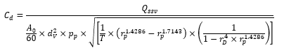 (89)
(89)
Where:
QSSV is the airflow rate at standard conditions (101.3 kPa, 273 K), m3/s
T is the temperature at the venturi inlet, K
dV is the diameter of the SSV throat, mm
rp is the ratio of the SSV throat to inlet absolute static pressure = 
rD is the ratio of the SSV throat diameter, dV, to the inlet pipe inner diameter D
To determine the range of subsonic flow, Cd shall be plotted as a function of Reynolds number Re, at the SSV throat. The Re at the SSV throat shall be calculated with the following equation:
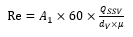 (90)
(90)
With
 (91)
(91)
Where:
A1 is 27.43831 in SI units of
QSSV is the airflow rate at standard conditions (101.3 kPa, 273 K), m3/s
dV is the diameter of the SSV throat, mm
μ is the absolute or dynamic viscosity of the gas, kg/ms
b is 1.458 x 10⁶ (empirical constant), kg/ms K0.5
S is 110.4 (empirical constant), K
Because QSSV is an input to the Re equation, the calculations shall be started with an initial guess for QSSV or Cd of the calibration venturi, and repeated until QSSV converges. The convergence method shall be accurate to 0.1 per cent of point or better.
For a minimum of sixteen points in the region of subsonic flow, the calculated values of Cd from the resulting calibration curve fit equation shall be within ±0.5 per cent of the measured Cd for each calibration point.
9.5.5. Total system verification
The total accuracy of the CVS sampling system and analytical system shall be determined by introducing a known mass of a pollutant gas into the system while it is being operated in the normal manner. The pollutant is analysed, and the mass calculated according to paragraph 8.5.2.3. except in the case of propane where a u factor of 0.000507 is used in place of 0.000483 for HC. Either of the following two techniques shall be used.
9.5.5.1. Metering with a critical flow orifice
A known quantity of pure gas (carbon monoxide or propane) shall be fed into the CVS system through a calibrated critical orifice. If the inlet pressure is high enough, the flow rate, which is adjusted by means of the critical flow orifice, is independent of the orifice outlet pressure (critical flow). The CVS system shall be operated as in a normal exhaust emission test for about 5 to 10 minutes. A gas sample shall be analyzed with the usual equipment (sampling bag or integrating method), and the mass of the gas calculated.
The mass so determined shall be within ±3 per cent of the known mass of the gas injected.
9.5.5.2. Metering by means of a gravimetric technique
The mass of a small cylinder filled with carbon monoxide or propane shall be determined with a precision of ±0.01 g. For about 5 to 10 minutes, the CVS system shall be operated as in a normal exhaust emission test, while carbon monoxide or propane is injected into the system. The quantity of pure gas discharged shall be determined by means of differential weighing. A gas sample shall be analyzed with the usual equipment (sampling bag or integrating method), and the mass of the gas calculated.
The mass so determined shall be within ±3 per cent of the known mass of the gas injected.
10. Particle number measurement test procedure
10.1. Sampling
Particle number emissions shall be measured by continuous sampling from either a partial flow dilution system, as described in Appendix 2 to this annex, paragraph A.2.2.1. and A.2.2.2. or a full flow dilution system as described in Appendix 2 to this annex, paragraph A.2.2.3. and A.2.2.4.
10.1.1. Diluent filtration
Diluent used for both the primary and, where applicable, secondary dilution of the exhaust in the dilution system shall be passed through filters meeting the High-Efficiency Particulate Air (HEPA) filter requirements defined in Appendix 2 to this annex, paragraphs A.2.2.2. or A.2.2.4. The diluent may optionally be charcoal scrubbed before being passed to the HEPA filter to reduce and stabilize the hydrocarbon concentrations in the diluent. It is recommended that an additional coarse particle filter is situated before the HEPA filter and after the charcoal scrubber, if used.
10.2. Compensating for particle number sample flow – full flow dilution systems
To compensate for the mass flow extracted from the dilution system for particle number sampling the extracted mass flow (filtered) shall be returned to the dilution system. Alternatively, the total mass flow in the dilution system may be mathematically corrected for the particle number sample flow extracted. Where the total mass flow extracted from the dilution system for the sum of particle number sampling and particulate mass sampling is less than 0.5 per cent of the total dilute exhaust gas flow in the dilution tunnel (med) this correction, or flow return, may be neglected.
10.3. Compensating for particle number sample flow – partial flow dilution systems
10.3.1. For partial flow dilution systems the mass flow extracted from the dilution system for particle number sampling shall be accounted for in controlling the proportionality of sampling. This shall be achieved either by feeding the particle number sample flow back into the dilution system upstream of the flow measuring device or by mathematical correction as outlined in paragraph 10.3.2. In the case of total sampling type partial flow dilution systems, the mass flow extracted for particle number sampling shall also be corrected for in the particulate mass calculation as outlined in paragraph 10.3.3.
10.3.2. The instantaneous exhaust gas flow rate into the dilution system (qmp), used for controlling the proportionality of sampling, shall be corrected according to one of the following methods:
(a) In the case where the extracted particle number sample flow is discarded, equation 83 in paragraph 9.4.6.2. shall be replaced by the following:
 (92)
(92)
Where:
qmp = sample flow of exhaust gas into partial flow dilution system, kg/s,
qmdew = diluted exhaust mass flow rate, kg/s,
qmdw = dilution air mass flow rate, kg/s,
qex = particle number sample mass flow rate, kg/s.
The qex signal sent to the partial flow system controller shall be accurate to within 0.1 per cent of qmdew at all times and should be sent with frequency of at least 1 Hz.
(b) In the case where the extracted particle number sample flow is fully or partially discarded, but an equivalent flow is fed back to the dilution system upstream of the flow measurement device, equation 83 in paragraph 9.4.6.2. shall be replaced by the following:
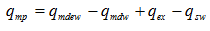 (93)
(93)
Where:
qmp = sample flow of exhaust gas into partial flow dilution system, kg/s,
qmdew = diluted exhaust mass flow rate, kg/s,
qmdw = dilution air mass flow rate, kg/s,
qex = particle number sample mass flow rate, kg/s,
qsw = mass flow rate fed back into dilution tunnel to compensate for particle number sample extraction, kg/s.
The difference between qex and qsw sent to the partial flow system controller shall be accurate to within 0.1 per cent of qmdew at all times. The signal (or signals) should be sent with frequency of at least 1 Hz.
10.3.3. Correction of PM measurement
When a particle number sample flow is extracted from a total sampling partial flow dilution system, the mass of particulates (mPM) calculated in paragraph 8.4.3.2.1. or 8.4.3.2.2. shall be corrected as follows to account for the flow extracted. This correction is required even where filtered extracted flow is fed back into the partial flow dilution systems.
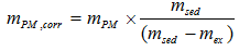 (94)
(94)
Where:
mPM,corr = mass of particulates corrected for extraction of particle number sample flow, g/test,
mPM = mass of particulates determined according to paragraph 8.4.3.2.1. or 8.4.3.2.2., g/test,
msed = total mass of diluted exhaust gas passing through the dilution tunnel, kg,
mex = total mass of diluted exhaust gas extracted from the dilution tunnel for particle number sampling, kg.
10.3.4. Proportionality of partial flow dilution sampling
For particle number measurement, exhaust mass flow rate, determined according to any of the methods described in paragraphs 8.4.1.3. to 8.4.1.7., is used for controlling the partial flow dilution system to take a sample proportional to the exhaust mass flow rate. The quality of proportionality shall be checked by applying a regression analysis between sample and exhaust flow in accordance with paragraph 9.4.6.1.
10.4. Determination of particle numbers
10.4.1. Time alignment
For partial flow dilution systems residence time in the particle number sampling and measurement system shall be accounted for by time aligning the particle number signal with the test cycle and the exhaust gas mass flow rate according to the procedure in paragraph 8.4.2.2. The transformation time of the particle number sampling and measurement system shall be determined according to paragraph A.8.1.3.7. of Appendix 8 to this annex.
10.4.2. Determination of particle numbers with a partial flow dilution system
Where particle numbers are sampled using a partial flow dilution system according to the procedures set out in paragraph 8.4., the number of particles
emitted over the test cycle shall be calculated by means of the following
equation:
 (95)
(95)
Where:
N = number of particles emitted over the test cycle,
medf = mass of equivalent diluted exhaust gas over the cycle, determined according to paragraph 8.4.3.2.1. or 8.4.3.2.2., kg/test,
k = calibration factor to correct the particle number counter measurements to the level of the reference instrument where this is not applied internally within the particle number counter. Where the calibration factor is applied internally within the particle number counter, a value of 1 shall be used for k in the above equation,
 = average concentration of particles from the diluted exhaust gas corrected to standard conditions (273.2 K and 101.33 kPa), particles per cubic centimetre,
 = mean particle concentration reduction factor of the volatile particle remover specific to the dilution settings used for the test.
 shall be calculated from the following equation:
 (96)
(96)
Where:
cs,i = a discrete measurement of particle concentration in the diluted gas exhaust from the particle counter, corrected for coincidence and to standard conditions (273.2 K and 101.33 kPa), particles per cubic centimetre,
n = number of particle concentration measurements taken over the duration of the test.
10.4.3. Determination of particle numbers with a full flow dilution system
Where particle numbers are sampled using a full flow dilution system according to the procedures set out in paragraph 8.5., the number of particles emitted over the test cycle shall be calculated by means of the following equation:
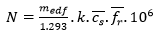 (97)
(97)
Where:
N = number of particles emitted over the test cycle,
med = total diluted exhaust gas flow over the cycle calculated according to any one of the methods described in paragraphs 8.5.1.2. to 8.5.1.4., kg/test,
k = calibration factor to correct the particle number counter measurements to the level of the reference instrument where this is not applied internally within the particle number counter. Where the calibration factor is applied internally within the particle number counter, a value of 1 shall be used for k in the above equation,
 = average corrected concentration of particles from the diluted exhaust gas corrected to standard conditions (273.2 K and 101.33 kPa), particles per cubic centimetre,
 = mean particle concentration reduction factor of the volatile particle remover specific to the dilution settings used for the test.
 shall be calculated from the following equation:
 (98)
(98)
Where:
cs,i = a discrete measurement of particle concentration in the diluted gas exhaust from the particle counter, corrected for coincidence and to standard conditions (273.2 K and 101.33 kPa), particles per cubic centimetre,
n = number of particle concentration measurements taken over the duration of the test.
10.4.4. Test result
10.4.4.1. Calculation of the specific emissions
For each individual WHSC, hot WHTC and cold WHTC the specific emissions in number of particles/kWh shall be calculated as follows:
 (99)
(99)
Where:
e = is the number of particles emitted per kWh,
Wact = is the actual cycle work according to paragraph 7.8.6., in kWh.
10.4.4.2. Exhaust after-treatment systems with periodic regeneration
For engines equipped with periodically regenerating after-treatment systems, the general provisions of paragraph 6.6.2. apply. The WHTC hot start emissions shall be weighted according to equation 5 where  is the average number of particles/kWh without regeneration, and
  is the average number of particles/kWh with regeneration. The calculation of the regeneration adjustment factors shall be done according to equations 6, 6a, 7 or 8, as appropriate.
10.4.4.3. Weighted average WHTC test result
For the WHTC, the final test result shall be a weighted average from cold start and hot start (including periodic regeneration where relevant) tests calculated using one of the following equations:
(a) In the case of multiplicative regeneration adjustment, or engines without periodically regenerating after-treatment
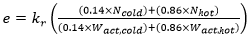 (100)
(100)
(b) In the case of additive regeneration adjustment
 (101)
(101)
Where:
Ncold = is the total number of particles emitted over the WHTC cold test cycle,
Nhot = is the total number of particles emitted over the WHTC hot test cycle,
Wact,cold = is the actual cycle work over the WHTC cold test cycle according to paragraph 7.8.6., in kWh,
Wact, hot = is the actual cycle work over the WHTC hot test cycle according to paragraph 7.8.6., in kWh,
kr = is the regeneration adjustment, according to paragraph 6.6.2., or in the case of engines without periodically regenerating after-treatment kr = 1
10.4.4.4. Rounding of final results
The final WHSC and weighted average WHTC test results shall be rounded in one step to three significant figures in accordance with ASTM E 29–06B. No rounding of intermediate values leading to the final brake specific emission result is permissible.
10.5. Determination of particle number background
10.5.1. At the engine manufacturer’s request, dilution tunnel background particle number concentrations may be sampled, prior to or after the test, from a point downstream of the particle and hydrocarbon filters into the particle number measurement system, to determine the tunnel background particle concentrations.
10.5.2. Subtraction of particle number tunnel background concentrations shall not be allowed for type approval, but may be used at the manufacturer’s request, with the prior approval of the Type Approval Authority , for conformity of production testing, if it can be demonstrated that tunnel background contribution is significant, which can then be subtracted from the values measured in the diluted exhaust.
Annex 4 ‑ Appendix 1 WHTC engine dynamometer schedule
Time | Norm. speed | Norm. torque | | Time | Norm. speed | Norm. torque | | Time | Norm. speed | Norm. torque |
| per cent | per cent | | s | per cent | per cent | | s | per cent | per cent |
1 | 0.0 | 0.0 | | 47 | 0.0 | 0.0 | | 93 | 32.8 | 32.7 |
2 | 0.0 | 0.0 | | 48 | 0.0 | 0.0 | | 94 | 33.7 | 32.5 |
3 | 0.0 | 0.0 | | 49 | 0.0 | 0.0 | | 95 | 34.4 | 29.5 |
4 | 0.0 | 0.0 | | 50 | 0.0 | 13.1 | | 96 | 34.3 | 26.5 |
5 | 0.0 | 0.0 | | 51 | 13.1 | 30.1 | | 97 | 34.4 | 24.7 |
6 | 0.0 | 0.0 | | 52 | 26.3 | 25.5 | | 98 | 35.0 | 24.9 |
7 | 1.5 | 8.9 | | 53 | 35.0 | 32.2 | | 99 | 35.6 | 25.2 |
8 | 15.8 | 30.9 | | 54 | 41.7 | 14.3 | | 100 | 36.1 | 24.8 |
9 | 27.4 | 1.3 | | 55 | 42.2 | 0.0 | | 101 | 36.3 | 24.0 |
10 | 32.6 | 0.7 | | 56 | 42.8 | 11.6 | | 102 | 36.2 | 23.6 |
11 | 34.8 | 1.2 | | 57 | 51.0 | 20.9 | | 103 | 36.2 | 23.5 |
12 | 36.2 | 7.4 | | 58 | 60.0 | 9.6 | | 104 | 36.8 | 22.7 |
13 | 37.1 | 6.2 | | 59 | 49.4 | 0.0 | | 105 | 37.2 | 20.9 |
14 | 37.9 | 10.2 | | 60 | 38.9 | 16.6 | | 106 | 37.0 | 19.2 |
15 | 39.6 | 12.3 | | 61 | 43.4 | 30.8 | | 107 | 36.3 | 18.4 |
16 | 42.3 | 12.5 | | 62 | 49.4 | 14.2 | | 108 | 35.4 | 17.6 |
17 | 45.3 | 12.6 | | 63 | 40.5 | 0.0 | | 109 | 35.2 | 14.9 |
18 | 48.6 | 6.0 | | 64 | 31.5 | 43.5 | | 110 | 35.4 | 9.9 |
19 | 40.8 | 0.0 | | 65 | 36.6 | 78.2 | | 111 | 35.5 | 4.3 |
20 | 33.0 | 16.3 | | 66 | 40.8 | 67.6 | | 112 | 35.2 | 6.6 |
21 | 42.5 | 27.4 | | 67 | 44.7 | 59.1 | | 113 | 34.9 | 10.0 |
22 | 49.3 | 26.7 | | 68 | 48.3 | 52.0 | | 114 | 34.7 | 25.1 |
23 | 54.0 | 18.0 | | 69 | 51.9 | 63.8 | | 115 | 34.4 | 29.3 |
24 | 57.1 | 12.9 | | 70 | 54.7 | 27.9 | | 116 | 34.5 | 20.7 |
25 | 58.9 | 8.6 | | 71 | 55.3 | 18.3 | | 117 | 35.2 | 16.6 |
26 | 59.3 | 6.0 | | 72 | 55.1 | 16.3 | | 118 | 35.8 | 16.2 |
27 | 59.0 | 4.9 | | 73 | 54.8 | 11.1 | | 119 | 35.6 | 20.3 |
28 | 57.9 | m | | 74 | 54.7 | 11.5 | | 120 | 35.3 | 22.5 |
29 | 55.7 | m | | 75 | 54.8 | 17.5 | | 121 | 35.3 | 23.4 |
30 | 52.1 | m | | 76 | 55.6 | 18.0 | | 122 | 34.7 | 11.9 |
31 | 46.4 | m | | 77 | 57.0 | 14.1 | | 123 | 45.5 | 0.0 |
32 | 38.6 | m | | 78 | 58.1 | 7.0 | | 124 | 56.3 | m |
33 | 29.0 | m | | 79 | 43.3 | 0.0 | | 125 | 46.2 | m |
34 | 20.8 | m | | 80 | 28.5 | 25.0 | | 126 | 50.1 | 0.0 |
35 | 16.9 | m | | 81 | 30.4 | 47.8 | | 127 | 54.0 | m |
36 | 16.9 | 42.5 | | 82 | 32.1 | 39.2 | | 128 | 40.5 | m |
37 | 18.8 | 38.4 | | 83 | 32.7 | 39.3 | | 129 | 27.0 | m |
38 | 20.7 | 32.9 | | 84 | 32.4 | 17.3 | | 130 | 13.5 | m |
39 | 21.0 | 0.0 | | 85 | 31.6 | 11.4 | | 131 | 0.0 | 0.0 |
40 | 19.1 | 0.0 | | 86 | 31.1 | 10.2 | | 132 | 0.0 | 0.0 |
41 | 13.7 | 0.0 | | 87 | 31.1 | 19.5 | | 133 | 0.0 | 0.0 |
42 | 2.2 | 0.0 | | 88 | 31.4 | 22.5 | | 134 | 0.0 | 0.0 |
43 | 0.0 | 0.0 | | 89 | 31.6 | 22.9 | | 135 | 0.0 | 0.0 |
44 | 0.0 | 0.0 | | 90 | 31.6 | 24.3 | | 136 | 0.0 | 0.0 |
45 | 0.0 | 0.0 | | 91 | 31.9 | 26.9 | | 137 | 0.0 | 0.0 |
46 | 0.0 | 0.0 | | 92 | 32.4 | 30.6 | | 138 | 0.0 | 0.0 |
139 | 0.0 | 0.0 | | 189 | 0.0 | 5.9 | | 239 | 0.0 | 0.0 |
140 | 0.0 | 0.0 | | 190 | 0.0 | 0.0 | | 240 | 0.0 | 0.0 |
141 | 0.0 | 0.0 | | 191 | 0.0 | 0.0 | | 241 | 0.0 | 0.0 |
142 | 0.0 | 4.9 | | 192 | 0.0 | 0.0 | | 242 | 0.0 | 0.0 |
143 | 0.0 | 7.3 | | 193 | 0.0 | 0.0 | | 243 | 0.0 | 0.0 |
144 | 4.4 | 28.7 | | 194 | 0.0 | 0.0 | | 244 | 0.0 | 0.0 |
145 | 11.1 | 26.4 | | 195 | 0.0 | 0.0 | | 245 | 0.0 | 0.0 |
146 | 15.0 | 9.4 | | 196 | 0.0 | 0.0 | | 246 | 0.0 | 0.0 |
147 | 15.9 | 0.0 | | 197 | 0.0 | 0.0 | | 247 | 0.0 | 0.0 |
148 | 15.3 | 0.0 | | 198 | 0.0 | 0.0 | | 248 | 0.0 | 0.0 |
149 | 14.2 | 0.0 | | 199 | 0.0 | 0.0 | | 249 | 0.0 | 0.0 |
150 | 13.2 | 0.0 | | 200 | 0.0 | 0.0 | | 250 | 0.0 | 0.0 |
151 | 11.6 | 0.0 | | 201 | 0.0 | 0.0 | | 251 | 0.0 | 0.0 |
152 | 8.4 | 0.0 | | 202 | 0.0 | 0.0 | | 252 | 0.0 | 0.0 |
153 | 5.4 | 0.0 | | 203 | 0.0 | 0.0 | | 253 | 0.0 | 31.6 |
154 | 4.3 | 5.6 | | 204 | 0.0 | 0.0 | | 254 | 9.4 | 13.6 |
155 | 5.8 | 24.4 | | 205 | 0.0 | 0.0 | | 255 | 22.2 | 16.9 |
156 | 9.7 | 20.7 | | 206 | 0.0 | 0.0 | | 256 | 33.0 | 53.5 |
157 | 13.6 | 21.1 | | 207 | 0.0 | 0.0 | | 257 | 43.7 | 22.1 |
158 | 15.6 | 21.5 | | 208 | 0.0 | 0.0 | | 258 | 39.8 | 0.0 |
159 | 16.5 | 21.9 | | 209 | 0.0 | 0.0 | | 259 | 36.0 | 45.7 |
160 | 18.0 | 22.3 | | 210 | 0.0 | 0.0 | | 260 | 47.6 | 75.9 |
161 | 21.1 | 46.9 | | 211 | 0.0 | 0.0 | | 261 | 61.2 | 70.4 |
162 | 25.2 | 33.6 | | 212 | 0.0 | 0.0 | | 262 | 72.3 | 70.4 |
163 | 28.1 | 16.6 | | 213 | 0.0 | 0.0 | | 263 | 76.0 | m |
164 | 28.8 | 7.0 | | 214 | 0.0 | 0.0 | | 264 | 74.3 | m |
165 | 27.5 | 5.0 | | 215 | 0.0 | 0.0 | | 265 | 68.5 | m |
166 | 23.1 | 3.0 | | 216 | 0.0 | 0.0 | | 266 | 61.0 | m |
167 | 16.9 | 1.9 | | 217 | 0.0 | 0.0 | | 267 | 56.0 | m |
168 | 12.2 | 2.6 | | 218 | 0.0 | 0.0 | | 268 | 54.0 | m |
169 | 9.9 | 3.2 | | 219 | 0.0 | 0.0 | | 269 | 53.0 | m |
170 | 9.1 | 4.0 | | 220 | 0.0 | 0.0 | | 270 | 50.8 | m |
171 | 8.8 | 3.8 | | 221 | 0.0 | 0.0 | | 271 | 46.8 | m |
172 | 8.5 | 12.2 | | 222 | 0.0 | 0.0 | | 272 | 41.7 | m |
173 | 8.2 | 29.4 | | 223 | 0.0 | 0.0 | | 273 | 35.9 | m |
174 | 9.6 | 20.1 | | 224 | 0.0 | 0.0 | | 274 | 29.2 | m |
175 | 14.7 | 16.3 | | 225 | 0.0 | 0.0 | | 275 | 20.7 | m |
176 | 24.5 | 8.7 | | 226 | 0.0 | 0.0 | | 276 | 10.1 | m |
177 | 39.4 | 3.3 | | 227 | 0.0 | 0.0 | | 277 | 0.0 | m |
178 | 39.0 | 2.9 | | 228 | 0.0 | 0.0 | | 278 | 0.0 | 0.0 |
179 | 38.5 | 5.9 | | 229 | 0.0 | 0.0 | | 279 | 0.0 | 0.0 |
180 | 42.4 | 8.0 | | 230 | 0.0 | 0.0 | | 280 | 0.0 | 0.0 |
181 | 38.2 | 6.0 | | 231 | 0.0 | 0.0 | | 281 | 0.0 | 0.0 |
182 | 41.4 | 3.8 | | 232 | 0.0 | 0.0 | | 282 | 0.0 | 0.0 |
183 | 44.6 | 5.4 | | 233 | 0.0 | 0.0 | | 283 | 0.0 | 0.0 |
184 | 38.8 | 8.2 | | 234 | 0.0 | 0.0 | | 284 | 0.0 | 0.0 |
185 | 37.5 | 8.9 | | 235 | 0.0 | 0.0 | | 285 | 0.0 | 0.0 |
186 | 35.4 | 7.3 | | 236 | 0.0 | 0.0 | | 286 | 0.0 | 0.0 |
187 | 28.4 | 7.0 | | 237 | 0.0 | 0.0 | | 287 | 0.0 | 0.0 |
188 | 14.8 | 7.0 | | 238 | 0.0 | 0.0 | | 288 | 0.0 | 0.0 |
| | | | | | | | | | |
289 | 0.0 | 0.0 | | 339 | 0.0 | 0.0 | | 389 | 25.2 | 14.7 |
290 | 0.0 | 0.0 | | 340 | 0.0 | 0.0 | | 390 | 28.6 | 28.4 |
291 | 0.0 | 0.0 | | 341 | 0.0 | 0.0 | | 391 | 35.5 | 65.0 |
292 | 0.0 | 0.0 | | 342 | 0.0 | 0.0 | | 392 | 43.8 | 75.3 |
293 | 0.0 | 0.0 | | 343 | 0.0 | 0.0 | | 393 | 51.2 | 34.2 |
294 | 0.0 | 0.0 | | 344 | 0.0 | 0.0 | | 394 | 40.7 | 0.0 |
295 | 0.0 | 0.0 | | 345 | 0.0 | 0.0 | | 395 | 30.3 | 45.4 |
296 | 0.0 | 0.0 | | 346 | 0.0 | 0.0 | | 396 | 34.2 | 83.1 |
297 | 0.0 | 0.0 | | 347 | 0.0 | 0.0 | | 397 | 37.6 | 85.3 |
298 | 0.0 | 0.0 | | 348 | 0.0 | 0.0 | | 398 | 40.8 | 87.5 |
299 | 0.0 | 0.0 | | 349 | 0.0 | 0.0 | | 399 | 44.8 | 89.7 |
300 | 0.0 | 0.0 | | 350 | 0.0 | 0.0 | | 400 | 50.6 | 91.9 |
301 | 0.0 | 0.0 | | 351 | 0.0 | 0.0 | | 401 | 57.6 | 94.1 |
302 | 0.0 | 0.0 | | 352 | 0.0 | 0.0 | | 402 | 64.6 | 44.6 |
303 | 0.0 | 0.0 | | 353 | 0.0 | 0.0 | | 403 | 51.6 | 0.0 |
304 | 0.0 | 0.0 | | 354 | 0.0 | 0.5 | | 404 | 38.7 | 37.4 |
305 | 0.0 | 0.0 | | 355 | 0.0 | 4.9 | | 405 | 42.4 | 70.3 |
306 | 0.0 | 0.0 | | 356 | 9.2 | 61.3 | | 406 | 46.5 | 89.1 |
307 | 0.0 | 0.0 | | 357 | 22.4 | 40.4 | | 407 | 50.6 | 93.9 |
308 | 0.0 | 0.0 | | 358 | 36.5 | 50.1 | | 408 | 53.8 | 33.0 |
309 | 0.0 | 0.0 | | 359 | 47.7 | 21.0 | | 409 | 55.5 | 20.3 |
310 | 0.0 | 0.0 | | 360 | 38.8 | 0.0 | | 410 | 55.8 | 5.2 |
311 | 0.0 | 0.0 | | 361 | 30.0 | 37.0 | | 411 | 55.4 | m |
312 | 0.0 | 0.0 | | 362 | 37.0 | 63.6 | | 412 | 54.4 | m |
313 | 0.0 | 0.0 | | 363 | 45.5 | 90.8 | | 413 | 53.1 | m |
314 | 0.0 | 0.0 | | 364 | 54.5 | 40.9 | | 414 | 51.8 | m |
315 | 0.0 | 0.0 | | 365 | 45.9 | 0.0 | | 415 | 50.3 | m |
316 | 0.0 | 0.0 | | 366 | 37.2 | 47.5 | | 416 | 48.4 | m |
317 | 0.0 | 0.0 | | 367 | 44.5 | 84.4 | | 417 | 45.9 | m |
318 | 0.0 | 0.0 | | 368 | 51.7 | 32.4 | | 418 | 43.1 | m |
319 | 0.0 | 0.0 | | 369 | 58.1 | 15.2 | | 419 | 40.1 | m |
320 | 0.0 | 0.0 | | 370 | 45.9 | 0.0 | | 420 | 37.4 | m |
321 | 0.0 | 0.0 | | 371 | 33.6 | 35.8 | | 421 | 35.1 | m |
322 | 0.0 | 0.0 | | 372 | 36.9 | 67.0 | | 422 | 32.8 | m |
323 | 0.0 | 0.0 | | 373 | 40.2 | 84.7 | | 423 | 45.3 | 0.0 |
324 | 4.5 | 41.0 | | 374 | 43.4 | 84.3 | | 424 | 57.8 | m |
325 | 17.2 | 38.9 | | 375 | 45.7 | 84.3 | | 425 | 50.6 | m |
326 | 30.1 | 36.8 | | 376 | 46.5 | m | | 426 | 41.6 | m |
327 | 41.0 | 34.7 | | 377 | 46.1 | m | | 427 | 47.9 | 0.0 |
328 | 50.0 | 32.6 | | 378 | 43.9 | m | | 428 | 54.2 | m |
329 | 51.4 | 0.1 | | 379 | 39.3 | m | | 429 | 48.1 | m |
330 | 47.8 | m | | 380 | 47.0 | m | | 430 | 47.0 | 31.3 |
331 | 40.2 | m | | 381 | 54.6 | m | | 431 | 49.0 | 38.3 |
332 | 32.0 | m | | 382 | 62.0 | m | | 432 | 52.0 | 40.1 |
333 | 24.4 | m | | 383 | 52.0 | m | | 433 | 53.3 | 14.5 |
334 | 16.8 | m | | 384 | 43.0 | m | | 434 | 52.6 | 0.8 |
335 | 8.1 | m | | 385 | 33.9 | m | | 435 | 49.8 | m |
336 | 0.0 | m | | 386 | 28.4 | m | | 436 | 51.0 | 18.6 |
337 | 0.0 | 0.0 | | 387 | 25.5 | m | | 437 | 56.9 | 38.9 |
338 | 0.0 | 0.0 | | 388 | 24.6 | 11.0 | | 438 | 67.2 | 45.0 |
| | | | | | | | | | |
439 | 78.6 | 21.5 | | 489 | 45.5 | m | | 539 | 56.7 | m |
440 | 65.5 | 0.0 | | 490 | 40.4 | m | | 540 | 46.9 | m |
441 | 52.4 | 31.3 | | 491 | 49.7 | 0.0 | | 541 | 37.5 | m |
442 | 56.4 | 60.1 | | 492 | 59.0 | m | | 542 | 30.3 | m |
443 | 59.7 | 29.2 | | 493 | 48.9 | m | | 543 | 27.3 | 32.3 |
444 | 45.1 | 0.0 | | 494 | 40.0 | m | | 544 | 30.8 | 60.3 |
445 | 30.6 | 4.2 | | 495 | 33.5 | m | | 545 | 41.2 | 62.3 |
446 | 30.9 | 8.4 | | 496 | 30.0 | m | | 546 | 36.0 | 0.0 |
447 | 30.5 | 4.3 | | 497 | 29.1 | 12.0 | | 547 | 30.8 | 32.3 |
448 | 44.6 | 0.0 | | 498 | 29.3 | 40.4 | | 548 | 33.9 | 60.3 |
449 | 58.8 | m | | 499 | 30.4 | 29.3 | | 549 | 34.6 | 38.4 |
450 | 55.1 | m | | 500 | 32.2 | 15.4 | | 550 | 37.0 | 16.6 |
451 | 50.6 | m | | 501 | 33.9 | 15.8 | | 551 | 42.7 | 62.3 |
452 | 45.3 | m | | 502 | 35.3 | 14.9 | | 552 | 50.4 | 28.1 |
453 | 39.3 | m | | 503 | 36.4 | 15.1 | | 553 | 40.1 | 0.0 |
454 | 49.1 | 0.0 | | 504 | 38.0 | 15.3 | | 554 | 29.9 | 8.0 |
455 | 58.8 | m | | 505 | 40.3 | 50.9 | | 555 | 32.5 | 15.0 |
456 | 50.7 | m | | 506 | 43.0 | 39.7 | | 556 | 34.6 | 63.1 |
457 | 42.4 | m | | 507 | 45.5 | 20.6 | | 557 | 36.7 | 58.0 |
458 | 44.1 | 0.0 | | 508 | 47.3 | 20.6 | | 558 | 39.4 | 52.9 |
459 | 45.7 | m | | 509 | 48.8 | 22.1 | | 559 | 42.8 | 47.8 |
460 | 32.5 | m | | 510 | 50.1 | 22.1 | | 560 | 46.8 | 42.7 |
461 | 20.7 | m | | 511 | 51.4 | 42.4 | | 561 | 50.7 | 27.5 |
462 | 10.0 | m | | 512 | 52.5 | 31.9 | | 562 | 53.4 | 20.7 |
463 | 0.0 | 0.0 | | 513 | 53.7 | 21.6 | | 563 | 54.2 | 13.1 |
464 | 0.0 | 1.5 | | 514 | 55.1 | 11.6 | | 564 | 54.2 | 0.4 |
465 | 0.9 | 41.1 | | 515 | 56.8 | 5.7 | | 565 | 53.4 | 0.0 |
466 | 7.0 | 46.3 | | 516 | 42.4 | 0.0 | | 566 | 51.4 | m |
467 | 12.8 | 48.5 | | 517 | 27.9 | 8.2 | | 567 | 48.7 | m |
468 | 17.0 | 50.7 | | 518 | 29.0 | 15.9 | | 568 | 45.6 | m |
469 | 20.9 | 52.9 | | 519 | 30.4 | 25.1 | | 569 | 42.4 | m |
470 | 26.7 | 55.0 | | 520 | 32.6 | 60.5 | | 570 | 40.4 | m |
471 | 35.5 | 57.2 | | 521 | 35.4 | 72.7 | | 571 | 39.8 | 5.8 |
472 | 46.9 | 23.8 | | 522 | 38.4 | 88.2 | | 572 | 40.7 | 39.7 |
473 | 44.5 | 0.0 | | 523 | 41.0 | 65.1 | | 573 | 43.8 | 37.1 |
474 | 42.1 | 45.7 | | 524 | 42.9 | 25.6 | | 574 | 48.1 | 39.1 |
475 | 55.6 | 77.4 | | 525 | 44.2 | 15.8 | | 575 | 52.0 | 22.0 |
476 | 68.8 | 100.0 | | 526 | 44.9 | 2.9 | | 576 | 54.7 | 13.2 |
477 | 81.7 | 47.9 | | 527 | 45.1 | m | | 577 | 56.4 | 13.2 |
478 | 71.2 | 0.0 | | 528 | 44.8 | m | | 578 | 57.5 | 6.6 |
479 | 60.7 | 38.3 | | 529 | 43.9 | m | | 579 | 42.6 | 0.0 |
480 | 68.8 | 72.7 | | 530 | 42.4 | m | | 580 | 27.7 | 10.9 |
481 | 75.0 | m | | 531 | 40.2 | m | | 581 | 28.5 | 21.3 |
482 | 61.3 | m | | 532 | 37.1 | m | | 582 | 29.2 | 23.9 |
483 | 53.5 | m | | 533 | 47.0 | 0.0 | | 583 | 29.5 | 15.2 |
484 | 45.9 | 58.0 | | 534 | 57.0 | m | | 584 | 29.7 | 8.8 |
485 | 48.1 | 80.0 | | 535 | 45.1 | m | | 585 | 30.4 | 20.8 |
486 | 49.4 | 97.9 | | 536 | 32.6 | m | | 586 | 31.9 | 22.9 |
487 | 49.7 | m | | 537 | 46.8 | 0.0 | | 587 | 34.3 | 61.4 |
488 | 48.7 | m | | 538 | 61.5 | m | | 588 | 37.2 | 76.6 |
| | | | | | | | | | |
589 | 40.1 | 27.5 | | 639 | 39.8 | m | | 689 | 46.6 | 0.0 |
590 | 42.3 | 25.4 | | 640 | 36.0 | m | | 690 | 32.3 | 34.6 |
591 | 43.5 | 32.0 | | 641 | 29.7 | m | | 691 | 32.7 | 68.6 |
592 | 43.8 | 6.0 | | 642 | 21.5 | m | | 692 | 32.6 | 67.0 |
593 | 43.5 | m | | 643 | 14.1 | m | | 693 | 31.3 | m |
594 | 42.8 | m | | 644 | 0.0 | 0.0 | | 694 | 28.1 | m |
595 | 41.7 | m | | 645 | 0.0 | 0.0 | | 695 | 43.0 | 0.0 |
596 | 40.4 | m | | 646 | 0.0 | 0.0 | | 696 | 58.0 | m |
597 | 39.3 | m | | 647 | 0.0 | 0.0 | | 697 | 58.9 | m |
598 | 38.9 | 12.9 | | 648 | 0.0 | 0.0 | | 698 | 49.4 | m |
599 | 39.0 | 18.4 | | 649 | 0.0 | 0.0 | | 699 | 41.5 | m |
600 | 39.7 | 39.2 | | 650 | 0.0 | 0.0 | | 700 | 48.4 | 0.0 |
601 | 41.4 | 60.0 | | 651 | 0.0 | 0.0 | | 701 | 55.3 | m |
602 | 43.7 | 54.5 | | 652 | 0.0 | 0.0 | | 702 | 41.8 | m |
603 | 46.2 | 64.2 | | 653 | 0.0 | 0.0 | | 703 | 31.6 | m |
604 | 48.8 | 73.3 | | 654 | 0.0 | 0.0 | | 704 | 24.6 | m |
605 | 51.0 | 82.3 | | 655 | 0.0 | 0.0 | | 705 | 15.2 | m |
606 | 52.1 | 0.0 | | 656 | 0.0 | 3.4 | | 706 | 7.0 | m |
607 | 52.0 | m | | 657 | 1.4 | 22.0 | | 707 | 0.0 | 0.0 |
608 | 50.9 | m | | 658 | 10.1 | 45.3 | | 708 | 0.0 | 0.0 |
609 | 49.4 | m | | 659 | 21.5 | 10.0 | | 709 | 0.0 | 0.0 |
610 | 47.8 | m | | 660 | 32.2 | 0.0 | | 710 | 0.0 | 0.0 |
611 | 46.6 | m | | 661 | 42.3 | 46.0 | | 711 | 0.0 | 0.0 |
612 | 47.3 | 35.3 | | 662 | 57.1 | 74.1 | | 712 | 0.0 | 0.0 |
613 | 49.2 | 74.1 | | 663 | 72.1 | 34.2 | | 713 | 0.0 | 0.0 |
614 | 51.1 | 95.2 | | 664 | 66.9 | 0.0 | | 714 | 0.0 | 0.0 |
615 | 51.7 | m | | 665 | 60.4 | 41.8 | | 715 | 0.0 | 0.0 |
616 | 50.8 | m | | 666 | 69.1 | 79.0 | | 716 | 0.0 | 0.0 |
617 | 47.3 | m | | 667 | 77.1 | 38.3 | | 717 | 0.0 | 0.0 |
618 | 41.8 | m | | 668 | 63.1 | 0.0 | | 718 | 0.0 | 0.0 |
619 | 36.4 | m | | 669 | 49.1 | 47.9 | | 719 | 0.0 | 0.0 |
620 | 30.9 | m | | 670 | 53.4 | 91.3 | | 720 | 0.0 | 0.0 |
621 | 25.5 | 37.1 | | 671 | 57.5 | 85.7 | | 721 | 0.0 | 0.0 |
622 | 33.8 | 38.4 | | 672 | 61.5 | 89.2 | | 722 | 0.0 | 0.0 |
623 | 42.1 | m | | 673 | 65.5 | 85.9 | | 723 | 0.0 | 0.0 |
624 | 34.1 | m | | 674 | 69.5 | 89.5 | | 724 | 0.0 | 0.0 |
625 | 33.0 | 37.1 | | 675 | 73.1 | 75.5 | | 725 | 0.0 | 0.0 |
626 | 36.4 | 38.4 | | 676 | 76.2 | 73.6 | | 726 | 0.0 | 0.0 |
627 | 43.3 | 17.1 | | 677 | 79.1 | 75.6 | | 727 | 0.0 | 0.0 |
628 | 35.7 | 0.0 | | 678 | 81.8 | 78.2 | | 728 | 0.0 | 0.0 |
629 | 28.1 | 11.6 | | 679 | 84.1 | 39.0 | | 729 | 0.0 | 0.0 |
630 | 36.5 | 19.2 | | 680 | 69.6 | 0.0 | | 730 | 0.0 | 0.0 |
631 | 45.2 | 8.3 | | 681 | 55.0 | 25.2 | | 731 | 0.0 | 0.0 |
632 | 36.5 | 0.0 | | 682 | 55.8 | 49.9 | | 732 | 0.0 | 0.0 |
633 | 27.9 | 32.6 | | 683 | 56.7 | 46.4 | | 733 | 0.0 | 0.0 |
634 | 31.5 | 59.6 | | 684 | 57.6 | 76.3 | | 734 | 0.0 | 0.0 |
635 | 34.4 | 65.2 | | 685 | 58.4 | 92.7 | | 735 | 0.0 | 0.0 |
636 | 37.0 | 59.6 | | 686 | 59.3 | 99.9 | | 736 | 0.0 | 0.0 |
637 | 39.0 | 49.0 | | 687 | 60.1 | 95.0 | | 737 | 0.0 | 0.0 |
638 | 40.2 | m | | 688 | 61.0 | 46.7 | | 738 | 0.0 | 0.0 |
| | | | | | | | | | |
739 | 0.0 | 0.0 | | 789 | 17.2 | m | | 839 | 38.1 | m |
740 | 0.0 | 0.0 | | 790 | 14.0 | 37.6 | | 840 | 37.2 | 42.7 |
741 | 0.0 | 0.0 | | 791 | 18.4 | 25.0 | | 841 | 37.5 | 70.8 |
742 | 0.0 | 0.0 | | 792 | 27.6 | 17.7 | | 842 | 39.1 | 48.6 |
743 | 0.0 | 0.0 | | 793 | 39.8 | 6.8 | | 843 | 41.3 | 0.1 |
744 | 0.0 | 0.0 | | 794 | 34.3 | 0.0 | | 844 | 42.3 | m |
745 | 0.0 | 0.0 | | 795 | 28.7 | 26.5 | | 845 | 42.0 | m |
746 | 0.0 | 0.0 | | 796 | 41.5 | 40.9 | | 846 | 40.8 | m |
747 | 0.0 | 0.0 | | 797 | 53.7 | 17.5 | | 847 | 38.6 | m |
748 | 0.0 | 0.0 | | 798 | 42.4 | 0.0 | | 848 | 35.5 | m |
749 | 0.0 | 0.0 | | 799 | 31.2 | 27.3 | | 849 | 32.1 | m |
750 | 0.0 | 0.0 | | 800 | 32.3 | 53.2 | | 850 | 29.6 | m |
751 | 0.0 | 0.0 | | 801 | 34.5 | 60.6 | | 851 | 28.8 | 39.9 |
752 | 0.0 | 0.0 | | 802 | 37.6 | 68.0 | | 852 | 29.2 | 52.9 |
753 | 0.0 | 0.0 | | 803 | 41.2 | 75.4 | | 853 | 30.9 | 76.1 |
754 | 0.0 | 0.0 | | 804 | 45.8 | 82.8 | | 854 | 34.3 | 76.5 |
755 | 0.0 | 0.0 | | 805 | 52.3 | 38.2 | | 855 | 38.3 | 75.5 |
756 | 0.0 | 0.0 | | 806 | 42.5 | 0.0 | | 856 | 42.5 | 74.8 |
757 | 0.0 | 0.0 | | 807 | 32.6 | 30.5 | | 857 | 46.6 | 74.2 |
758 | 0.0 | 0.0 | | 808 | 35.0 | 57.9 | | 858 | 50.7 | 76.2 |
759 | 0.0 | 0.0 | | 809 | 36.0 | 77.3 | | 859 | 54.8 | 75.1 |
760 | 0.0 | 0.0 | | 810 | 37.1 | 96.8 | | 860 | 58.7 | 36.3 |
761 | 0.0 | 0.0 | | 811 | 39.6 | 80.8 | | 861 | 45.2 | 0.0 |
762 | 0.0 | 0.0 | | 812 | 43.4 | 78.3 | | 862 | 31.8 | 37.2 |
763 | 0.0 | 0.0 | | 813 | 47.2 | 73.4 | | 863 | 33.8 | 71.2 |
764 | 0.0 | 0.0 | | 814 | 49.6 | 66.9 | | 864 | 35.5 | 46.4 |
765 | 0.0 | 0.0 | | 815 | 50.2 | 62.0 | | 865 | 36.6 | 33.6 |
766 | 0.0 | 0.0 | | 816 | 50.2 | 57.7 | | 866 | 37.2 | 20.0 |
767 | 0.0 | 0.0 | | 817 | 50.6 | 62.1 | | 867 | 37.2 | m |
768 | 0.0 | 0.0 | | 818 | 52.3 | 62.9 | | 868 | 37.0 | m |
769 | 0.0 | 0.0 | | 819 | 54.8 | 37.5 | | 869 | 36.6 | m |
770 | 0.0 | 0.0 | | 820 | 57.0 | 18.3 | | 870 | 36.0 | m |
771 | 0.0 | 22.0 | | 821 | 42.3 | 0.0 | | 871 | 35.4 | m |
772 | 4.5 | 25.8 | | 822 | 27.6 | 29.1 | | 872 | 34.7 | m |
773 | 15.5 | 42.8 | | 823 | 28.4 | 57.0 | | 873 | 34.1 | m |
774 | 30.5 | 46.8 | | 824 | 29.1 | 51.8 | | 874 | 33.6 | m |
775 | 45.5 | 29.3 | | 825 | 29.6 | 35.3 | | 875 | 33.3 | m |
776 | 49.2 | 13.6 | | 826 | 29.7 | 33.3 | | 876 | 33.1 | m |
777 | 39.5 | 0.0 | | 827 | 29.8 | 17.7 | | 877 | 32.7 | m |
778 | 29.7 | 15.1 | | 828 | 29.5 | m | | 878 | 31.4 | m |
779 | 34.8 | 26.9 | | 829 | 28.9 | m | | 879 | 45.0 | 0.0 |
780 | 40.0 | 13.6 | | 830 | 43.0 | 0.0 | | 880 | 58.5 | m |
781 | 42.2 | m | | 831 | 57.1 | m | | 881 | 53.7 | m |
782 | 42.1 | m | | 832 | 57.7 | m | | 882 | 47.5 | m |
783 | 40.8 | m | | 833 | 56.0 | m | | 883 | 40.6 | m |
784 | 37.7 | 37.6 | | 834 | 53.8 | m | | 884 | 34.1 | m |
785 | 47.0 | 35.0 | | 835 | 51.2 | m | | 885 | 45.3 | 0.0 |
786 | 48.8 | 33.4 | | 836 | 48.1 | m | | 886 | 56.4 | m |
787 | 41.7 | m | | 837 | 44.5 | m | | 887 | 51.0 | m |
788 | 27.7 | m | | 838 | 40.9 | m | | 888 | 44.5 | m |
| | | | | | | | | | |
889 | 36.4 | m | | 939 | 32.7 | 56.5 | | 989 | 32.6 | m |
890 | 26.6 | m | | 940 | 33.4 | 62.8 | | 990 | 30.9 | m |
891 | 20.0 | m | | 941 | 34.6 | 68.2 | | 991 | 29.9 | m |
892 | 13.3 | m | | 942 | 35.8 | 68.6 | | 992 | 29.2 | m |
893 | 6.7 | m | | 943 | 38.6 | 65.0 | | 993 | 44.1 | 0.0 |
894 | 0.0 | 0.0 | | 944 | 42.3 | 61.9 | | 994 | 59.1 | m |
895 | 0.0 | 0.0 | | 945 | 44.1 | 65.3 | | 995 | 56.8 | m |
896 | 0.0 | 0.0 | | 946 | 45.3 | 63.2 | | 996 | 53.5 | m |
897 | 0.0 | 0.0 | | 947 | 46.5 | 30.6 | | 997 | 47.8 | m |
898 | 0.0 | 0.0 | | 948 | 46.7 | 11.1 | | 998 | 41.9 | m |
899 | 0.0 | 0.0 | | 949 | 45.9 | 16.1 | | 999 | 35.9 | m |
900 | 0.0 | 0.0 | | 950 | 45.6 | 21.8 | | 1000 | 44.3 | 0.0 |
901 | 0.0 | 5.8 | | 951 | 45.9 | 24.2 | | 1001 | 52.6 | m |
902 | 2.5 | 27.9 | | 952 | 46.5 | 24.7 | | 1002 | 43.4 | m |
903 | 12.4 | 29.0 | | 953 | 46.7 | 24.7 | | 1003 | 50.6 | 0.0 |
904 | 19.4 | 30.1 | | 954 | 46.8 | 28.2 | | 1004 | 57.8 | m |
905 | 29.3 | 31.2 | | 955 | 47.2 | 31.2 | | 1005 | 51.6 | m |
906 | 37.1 | 10.4 | | 956 | 47.6 | 29.6 | | 1006 | 44.8 | m |
907 | 40.6 | 4.9 | | 957 | 48.2 | 31.2 | | 1007 | 48.6 | 0.0 |
908 | 35.8 | 0.0 | | 958 | 48.6 | 33.5 | | 1008 | 52.4 | m |
909 | 30.9 | 7.6 | | 959 | 48.8 | m | | 1009 | 45.4 | m |
910 | 35.4 | 13.8 | | 960 | 47.6 | m | | 1010 | 37.2 | m |
911 | 36.5 | 11.1 | | 961 | 46.3 | m | | 1011 | 26.3 | m |
912 | 40.8 | 48.5 | | 962 | 45.2 | m | | 1012 | 17.9 | m |
913 | 49.8 | 3.7 | | 963 | 43.5 | m | | 1013 | 16.2 | 1.9 |
914 | 41.2 | 0.0 | | 964 | 41.4 | m | | 1014 | 17.8 | 7.5 |
915 | 32.7 | 29.7 | | 965 | 40.3 | m | | 1015 | 25.2 | 18.0 |
916 | 39.4 | 52.1 | | 966 | 39.4 | m | | 1016 | 39.7 | 6.5 |
917 | 48.8 | 22.7 | | 967 | 38.0 | m | | 1017 | 38.6 | 0.0 |
918 | 41.6 | 0.0 | | 968 | 36.3 | m | | 1018 | 37.4 | 5.4 |
919 | 34.5 | 46.6 | | 969 | 35.3 | 5.8 | | 1019 | 43.4 | 9.7 |
920 | 39.7 | 84.4 | | 970 | 35.4 | 30.2 | | 1020 | 46.9 | 15.7 |
921 | 44.7 | 83.2 | | 971 | 36.6 | 55.6 | | 1021 | 52.5 | 13.1 |
922 | 49.5 | 78.9 | | 972 | 38.6 | 48.5 | | 1022 | 56.2 | 6.3 |
923 | 52.3 | 83.8 | | 973 | 39.9 | 41.8 | | 1023 | 44.0 | 0.0 |
924 | 53.4 | 77.7 | | 974 | 40.3 | 38.2 | | 1024 | 31.8 | 20.9 |
925 | 52.1 | 69.6 | | 975 | 40.8 | 35.0 | | 1025 | 38.7 | 36.3 |
926 | 47.9 | 63.6 | | 976 | 41.9 | 32.4 | | 1026 | 47.7 | 47.5 |
927 | 46.4 | 55.2 | | 977 | 43.2 | 26.4 | | 1027 | 54.5 | 22.0 |
928 | 46.5 | 53.6 | | 978 | 43.5 | m | | 1028 | 41.3 | 0.0 |
929 | 46.4 | 62.3 | | 979 | 42.9 | m | | 1029 | 28.1 | 26.8 |
930 | 46.1 | 58.2 | | 980 | 41.5 | m | | 1030 | 31.6 | 49.2 |
931 | 46.2 | 61.8 | | 981 | 40.9 | m | | 1031 | 34.5 | 39.5 |
932 | 47.3 | 62.3 | | 982 | 40.5 | m | | 1032 | 36.4 | 24.0 |
933 | 49.3 | 57.1 | | 983 | 39.5 | m | | 1033 | 36.7 | m |
934 | 52.6 | 58.1 | | 984 | 38.3 | m | | 1034 | 35.5 | m |
935 | 56.3 | 56.0 | | 985 | 36.9 | m | | 1035 | 33.8 | m |
936 | 59.9 | 27.2 | | 986 | 35.4 | m | | 1036 | 33.7 | 19.8 |
937 | 45.8 | 0.0 | | 987 | 34.5 | m | | 1037 | 35.3 | 35.1 |
938 | 31.8 | 28.8 | | 988 | 33.9 | m | | 1038 | 38.0 | 33.9 |
| | | | | | | | | | |
1039 | 40.1 | 34.5 | | 1,089 | 46.3 | 24.0 | | 1139 | 51.7 | 0.0 |
1040 | 42.2 | 40.4 | | 1,090 | 47.8 | 20.6 | | 1140 | 59.2 | m |
1041 | 45.2 | 44.0 | | 1,091 | 47.2 | 3.8 | | 1141 | 47.2 | m |
1042 | 48.3 | 35.9 | | 1,092 | 45.6 | 4.4 | | 1142 | 35.1 | 0.0 |
1043 | 50.1 | 29.6 | | 1,093 | 44.6 | 4.1 | | 1143 | 23.1 | m |
1044 | 52.3 | 38.5 | | 1,094 | 44.1 | m | | 1144 | 13.1 | m |
1045 | 55.3 | 57.7 | | 1,095 | 42.9 | m | | 1145 | 5.0 | m |
1046 | 57.0 | 50.7 | | 1,096 | 40.9 | m | | 1146 | 0.0 | 0.0 |
1047 | 57.7 | 25.2 | | 1,097 | 39.2 | m | | 1147 | 0.0 | 0.0 |
1048 | 42.9 | 0.0 | | 1,098 | 37.0 | m | | 1148 | 0.0 | 0.0 |
1049 | 28.2 | 15.7 | | 1,099 | 35.1 | 2.0 | | 1149 | 0.0 | 0.0 |
1050 | 29.2 | 30.5 | | 1,100 | 35.6 | 43.3 | | 1150 | 0.0 | 0.0 |
1051 | 31.1 | 52.6 | | 1,101 | 38.7 | 47.6 | | 1151 | 0.0 | 0.0 |
1052 | 33.4 | 60.7 | | 1,102 | 41.3 | 40.4 | | 1152 | 0.0 | 0.0 |
1053 | 35.0 | 61.4 | | 1,103 | 42.6 | 45.7 | | 1153 | 0.0 | 0.0 |
1054 | 35.3 | 18.2 | | 1,104 | 43.9 | 43.3 | | 1154 | 0.0 | 0.0 |
1055 | 35.2 | 14.9 | | 1,105 | 46.9 | 41.2 | | 1155 | 0.0 | 0.0 |
1056 | 34.9 | 11.7 | | 1,106 | 52.4 | 40.1 | | 1156 | 0.0 | 0.0 |
1057 | 34.5 | 12.9 | | 1,107 | 56.3 | 39.3 | | 1157 | 0.0 | 0.0 |
1058 | 34.1 | 15.5 | | 1108 | 57.4 | 25.5 | | 1158 | 0.0 | 0.0 |
1059 | 33.5 | m | | 1109 | 57.2 | 25.4 | | 1159 | 0.0 | 0.0 |
1060 | 31.8 | m | | 1110 | 57.0 | 25.4 | | 1160 | 0.0 | 0.0 |
1061 | 30.1 | m | | 1111 | 56.8 | 25.3 | | 1161 | 0.0 | 0.0 |
1062 | 29.6 | 10.3 | | 1112 | 56.3 | 25.3 | | 1162 | 0.0 | 0.0 |
1063 | 30.0 | 26.5 | | 1113 | 55.6 | 25.2 | | 1163 | 0.0 | 0.0 |
1064 | 31.0 | 18.8 | | 1114 | 56.2 | 25.2 | | 1164 | 0.0 | 0.0 |
1065 | 31.5 | 26.5 | | 1115 | 58.0 | 12.4 | | 1165 | 0.0 | 0.0 |
1066 | 31.7 | m | | 1116 | 43.4 | 0.0 | | 1166 | 0.0 | 0.0 |
1067 | 31.5 | m | | 1117 | 28.8 | 26.2 | | 1167 | 0.0 | 0.0 |
1068 | 30.6 | m | | 1118 | 30.9 | 49.9 | | 1168 | 0.0 | 0.0 |
1069 | 30.0 | m | | 1119 | 32.3 | 40.5 | | 1169 | 0.0 | 0.0 |
1070 | 30.0 | m | | 1120 | 32.5 | 12.4 | | 1170 | 0.0 | 0.0 |
1071 | 29.4 | m | | 1121 | 32.4 | 12.2 | | 1171 | 0.0 | 0.0 |
1072 | 44.3 | 0.0 | | 1122 | 32.1 | 6.4 | | 1172 | 0.0 | 0.0 |
1073 | 59.2 | m | | 1123 | 31.0 | 12.4 | | 1173 | 0.0 | 0.0 |
1074 | 58.3 | m | | 1124 | 30.1 | 18.5 | | 1174 | 0.0 | 0.0 |
1075 | 57.1 | m | | 1125 | 30.4 | 35.6 | | 1175 | 0.0 | 0.0 |
1076 | 55.4 | m | | 1126 | 31.2 | 30.1 | | 1176 | 0.0 | 0.0 |
1077 | 53.5 | m | | 1127 | 31.5 | 30.8 | | 1177 | 0.0 | 0.0 |
1078 | 51.5 | m | | 1128 | 31.5 | 26.9 | | 1178 | 0.0 | 0.0 |
1079 | 49.7 | m | | 1129 | 31.7 | 33.9 | | 1179 | 0.0 | 0.0 |
1080 | 47.9 | m | | 1130 | 32.0 | 29.9 | | 1180 | 0.0 | 0.0 |
1081 | 46.4 | m | | 1131 | 32.1 | m | | 1181 | 0.0 | 0.0 |
1082 | 45.5 | m | | 1132 | 31.4 | m | | 1182 | 0.0 | 0.0 |
1083 | 45.2 | m | | 1133 | 30.3 | m | | 1183 | 0.0 | 0.0 |
1084 | 44.3 | m | | 1134 | 29.8 | m | | 1184 | 0.0 | 0.0 |
1085 | 43.6 | m | | 1135 | 44.3 | 0.0 | | 1185 | 0.0 | 0.0 |
1086 | 43.1 | m | | 1136 | 58.9 | m | | 1186 | 0.0 | 0.0 |
1087 | 42.5 | 25.6 | | 1137 | 52.1 | m | | 1187 | 0.0 | 0.0 |
1088 | 43.3 | 25.7 | | 1138 | 44.1 | m | | 1188 | 0.0 | 0.0 |
| | | | | | | | | | |
1189 | 0.0 | 0.0 | | 1239 | 58.5 | 85.4 | | 1289 | 61.9 | 76.1 |
1190 | 0.0 | 0.0 | | 1240 | 59.5 | 85.6 | | 1290 | 65.6 | 73.7 |
1191 | 0.0 | 0.0 | | 1241 | 61.0 | 86.6 | | 1291 | 69.9 | 79.3 |
1192 | 0.0 | 0.0 | | 1242 | 62.6 | 86.8 | | 1292 | 74.1 | 81.3 |
1193 | 0.0 | 0.0 | | 1243 | 64.1 | 87.6 | | 1293 | 78.3 | 83.2 |
1194 | 0.0 | 0.0 | | 1244 | 65.4 | 87.5 | | 1294 | 82.6 | 86.0 |
1195 | 0.0 | 0.0 | | 1245 | 66.7 | 87.8 | | 1295 | 87.0 | 89.5 |
1196 | 0.0 | 20.4 | | 1246 | 68.1 | 43.5 | | 1296 | 91.2 | 90.8 |
1197 | 12.6 | 41.2 | | 1247 | 55.2 | 0.0 | | 1297 | 95.3 | 45.9 |
1198 | 27.3 | 20.4 | | 1248 | 42.3 | 37.2 | | 1298 | 81.0 | 0.0 |
1199 | 40.4 | 7.6 | | 1249 | 43.0 | 73.6 | | 1299 | 66.6 | 38.2 |
1200 | 46.1 | m | | 1250 | 43.5 | 65.1 | | 1300 | 67.9 | 75.5 |
1201 | 44.6 | m | | 1251 | 43.8 | 53.1 | | 1301 | 68.4 | 80.5 |
1202 | 42.7 | 14.7 | | 1252 | 43.9 | 54.6 | | 1302 | 69.0 | 85.5 |
1203 | 42.9 | 7.3 | | 1253 | 43.9 | 41.2 | | 1303 | 70.0 | 85.2 |
1204 | 36.1 | 0.0 | | 1254 | 43.8 | 34.8 | | 1304 | 71.6 | 85.9 |
1205 | 29.3 | 15.0 | | 1255 | 43.6 | 30.3 | | 1305 | 73.3 | 86.2 |
1206 | 43.8 | 22.6 | | 1256 | 43.3 | 21.9 | | 1306 | 74.8 | 86.5 |
1207 | 54.9 | 9.9 | | 1257 | 42.8 | 19.9 | | 1307 | 76.3 | 42.9 |
1208 | 44.9 | 0.0 | | 1258 | 42.3 | m | | 1308 | 63.3 | 0.0 |
1209 | 34.9 | 47.4 | | 1259 | 41.4 | m | | 1309 | 50.4 | 21.2 |
1210 | 42.7 | 82.7 | | 1260 | 40.2 | m | | 1310 | 50.6 | 42.3 |
1211 | 52.0 | 81.2 | | 1261 | 38.7 | m | | 1311 | 50.6 | 53.7 |
1212 | 61.8 | 82.7 | | 1262 | 37.1 | m | | 1312 | 50.4 | 90.1 |
1213 | 71.3 | 39.1 | | 1263 | 35.6 | m | | 1313 | 50.5 | 97.1 |
1214 | 58.1 | 0.0 | | 1264 | 34.2 | m | | 1314 | 51.0 | 100.0 |
1215 | 44.9 | 42.5 | | 1265 | 32.9 | m | | 1315 | 51.9 | 100.0 |
1216 | 46.3 | 83.3 | | 1266 | 31.8 | m | | 1316 | 52.6 | 100.0 |
1217 | 46.8 | 74.1 | | 1267 | 30.7 | m | | 1317 | 52.8 | 32.4 |
1218 | 48.1 | 75.7 | | 1268 | 29.6 | m | | 1318 | 47.7 | 0.0 |
1219 | 50.5 | 75.8 | | 1269 | 40.4 | 0.0 | | 1319 | 42.6 | 27.4 |
1220 | 53.6 | 76.7 | | 1270 | 51.2 | m | | 1320 | 42.1 | 53.5 |
1221 | 56.9 | 77.1 | | 1271 | 49.6 | m | | 1321 | 41.8 | 44.5 |
1222 | 60.2 | 78.7 | | 1272 | 48.0 | m | | 1322 | 41.4 | 41.1 |
1223 | 63.7 | 78.0 | | 1273 | 46.4 | m | | 1323 | 41.0 | 21.0 |
1224 | 67.2 | 79.6 | | 1274 | 45.0 | m | | 1324 | 40.3 | 0.0 |
1225 | 70.7 | 80.9 | | 1275 | 43.6 | m | | 1325 | 39.3 | 1.0 |
1226 | 74.1 | 81.1 | | 1276 | 42.3 | m | | 1326 | 38.3 | 15.2 |
1227 | 77.5 | 83.6 | | 1277 | 41.0 | m | | 1327 | 37.6 | 57.8 |
1228 | 80.8 | 85.6 | | 1278 | 39.6 | m | | 1328 | 37.3 | 73.2 |
1229 | 84.1 | 81.6 | | 1279 | 38.3 | m | | 1329 | 37.3 | 59.8 |
1230 | 87.4 | 88.3 | | 1280 | 37.1 | m | | 1330 | 37.4 | 52.2 |
1231 | 90.5 | 91.9 | | 1281 | 35.9 | m | | 1331 | 37.4 | 16.9 |
1232 | 93.5 | 94.1 | | 1282 | 34.6 | m | | 1332 | 37.1 | 34.3 |
1233 | 96.8 | 96.6 | | 1283 | 33.0 | m | | 1333 | 36.7 | 51.9 |
1234 | 100.0 | m | | 1284 | 31.1 | m | | 1334 | 36.2 | 25.3 |
1235 | 96.0 | m | | 1285 | 29.2 | m | | 1335 | 35.6 | m |
1236 | 81.9 | m | | 1286 | 43.3 | 0.0 | | 1336 | 34.6 | m |
1237 | 68.1 | m | | 1287 | 57.4 | 32.8 | | 1337 | 33.2 | m |
1238 | 58.1 | 84.7 | | 1288 | 59.9 | 65.4 | | 1338 | 31.6 | m |
| | | | | | | | | | |
1339 | 30.1 | m | | 1389 | 50.4 | 50.2 | | 1439 | 36.3 | 98.8 |
1340 | 28.8 | m | | 1390 | 53.0 | 26.1 | | 1440 | 37.7 | 100.0 |
1341 | 28.0 | 29.5 | | 1391 | 59.5 | 0.0 | | 1441 | 39.2 | 100.0 |
1342 | 28.6 | 100.0 | | 1392 | 66.2 | 38.4 | | 1442 | 40.9 | 100.0 |
1343 | 28.8 | 97.3 | | 1393 | 66.4 | 76.7 | | 1443 | 42.4 | 99.5 |
1344 | 28.8 | 73.4 | | 1394 | 67.6 | 100.0 | | 1444 | 43.8 | 98.7 |
1345 | 29.6 | 56.9 | | 1395 | 68.4 | 76.6 | | 1445 | 45.4 | 97.3 |
1346 | 30.3 | 91.7 | | 1396 | 68.2 | 47.2 | | 1446 | 47.0 | 96.6 |
1347 | 31.0 | 90.5 | | 1397 | 69.0 | 81.4 | | 1447 | 47.8 | 96.2 |
1348 | 31.8 | 81.7 | | 1398 | 69.7 | 40.6 | | 1448 | 48.8 | 96.3 |
1349 | 32.6 | 79.5 | | 1399 | 54.7 | 0.0 | | 1449 | 50.5 | 95.1 |
1350 | 33.5 | 86.9 | | 1400 | 39.8 | 19.9 | | 1450 | 51.0 | 95.9 |
1351 | 34.6 | 100.0 | | 1401 | 36.3 | 40.0 | | 1451 | 52.0 | 94.3 |
1352 | 35.6 | 78.7 | | 1402 | 36.7 | 59.4 | | 1452 | 52.6 | 94.6 |
1353 | 36.4 | 50.5 | | 1403 | 36.6 | 77.5 | | 1453 | 53.0 | 65.5 |
1354 | 37.0 | 57.0 | | 1404 | 36.8 | 94.3 | | 1454 | 53.2 | 0.0 |
1355 | 37.3 | 69.1 | | 1405 | 36.8 | 100.0 | | 1455 | 53.2 | m |
1356 | 37.6 | 49.5 | | 1406 | 36.4 | 100.0 | | 1456 | 52.6 | m |
1357 | 37.8 | 44.4 | | 1407 | 36.3 | 79.7 | | 1457 | 52.1 | m |
1358 | 37.8 | 43.4 | | 1408 | 36.7 | 49.5 | | 1458 | 51.8 | m |
1359 | 37.8 | 34.8 | | 1409 | 36.6 | 39.3 | | 1459 | 51.3 | m |
1360 | 37.6 | 24.0 | | 1410 | 37.3 | 62.8 | | 1460 | 50.7 | m |
1361 | 37.2 | m | | 1411 | 38.1 | 73.4 | | 1461 | 50.7 | m |
1362 | 36.3 | m | | 1412 | 39.0 | 72.9 | | 1462 | 49.8 | m |
1363 | 35.1 | m | | 1413 | 40.2 | 72.0 | | 1463 | 49.4 | m |
1364 | 33.7 | m | | 1414 | 41.5 | 71.2 | | 1464 | 49.3 | m |
1365 | 32.4 | m | | 1415 | 42.9 | 77.3 | | 1465 | 49.1 | m |
1366 | 31.1 | m | | 1416 | 44.4 | 76.6 | | 1466 | 49.1 | m |
1367 | 29.9 | m | | 1417 | 45.4 | 43.1 | | 1467 | 49.1 | 8.3 |
1368 | 28.7 | m | | 1418 | 45.3 | 53.9 | | 1468 | 48.9 | 16.8 |
1369 | 29.0 | 58.6 | | 1419 | 45.1 | 64.8 | | 1469 | 48.8 | 21.3 |
1370 | 29.7 | 88.5 | | 1420 | 46.5 | 74.2 | | 1470 | 49.1 | 22.1 |
1371 | 31.0 | 86.3 | | 1421 | 47.7 | 75.2 | | 1471 | 49.4 | 26.3 |
1372 | 31.8 | 43.4 | | 1422 | 48.1 | 75.5 | | 1472 | 49.8 | 39.2 |
1373 | 31.7 | m | | 1423 | 48.6 | 75.8 | | 1473 | 50.4 | 83.4 |
1374 | 29.9 | m | | 1424 | 48.9 | 76.3 | | 1474 | 51.4 | 90.6 |
1375 | 40.2 | 0.0 | | 1425 | 49.9 | 75.5 | | 1475 | 52.3 | 93.8 |
1376 | 50.4 | m | | 1426 | 50.4 | 75.2 | | 1476 | 53.3 | 94.0 |
1377 | 47.9 | m | | 1427 | 51.1 | 74.6 | | 1477 | 54.2 | 94.1 |
1378 | 45.0 | m | | 1428 | 51.9 | 75.0 | | 1478 | 54.9 | 94.3 |
1379 | 43.0 | m | | 1429 | 52.7 | 37.2 | | 1479 | 55.7 | 94.6 |
1380 | 40.6 | m | | 1430 | 41.6 | 0.0 | | 1480 | 56.1 | 94.9 |
1381 | 55.5 | 0.0 | | 1431 | 30.4 | 36.6 | | 1481 | 56.3 | 86.2 |
1382 | 70.4 | 41.7 | | 1432 | 30.5 | 73.2 | | 1482 | 56.2 | 64.1 |
1383 | 73.4 | 83.2 | | 1433 | 30.3 | 81.6 | | 1483 | 56.0 | 46.1 |
1384 | 74.0 | 83.7 | | 1434 | 30.4 | 89.3 | | 1484 | 56.2 | 33.4 |
1385 | 74.9 | 41.7 | | 1435 | 31.5 | 90.4 | | 1485 | 56.5 | 23.6 |
1386 | 60.0 | 0.0 | | 1436 | 32.7 | 88.5 | | 1486 | 56.3 | 18.6 |
1387 | 45.1 | 41.6 | | 1437 | 33.7 | 97.2 | | 1487 | 55.7 | 16.2 |
1388 | 47.7 | 84.2 | | 1438 | 35.2 | 99.7 | | 1488 | 56.0 | 15.9 |
| | | | | | | | | | |
1489 | 55.9 | 21.8 | | 1539 | 57.0 | 59.5 | | 1589 | 56.8 | 42.9 |
1490 | 55.8 | 20.9 | | 1540 | 56.7 | 57.0 | | 1590 | 56.5 | 42.8 |
1491 | 55.4 | 18.4 | | 1541 | 56.7 | 69.8 | | 1591 | 56.7 | 43.2 |
1492 | 55.7 | 25.1 | | 1542 | 56.8 | 58.5 | | 1592 | 56.5 | 42.8 |
1493 | 56.0 | 27.7 | | 1543 | 56.8 | 47.2 | | 1593 | 56.9 | 42.2 |
1494 | 55.8 | 22.4 | | 1544 | 57.0 | 38.5 | | 1594 | 56.5 | 43.1 |
1495 | 56.1 | 20.0 | | 1545 | 57.0 | 32.8 | | 1595 | 56.5 | 42.9 |
1496 | 55.7 | 17.4 | | 1546 | 56.8 | 30.2 | | 1596 | 56.7 | 42.7 |
1497 | 55.9 | 20.9 | | 1547 | 57.0 | 27.0 | | 1597 | 56.6 | 41.5 |
1498 | 56.0 | 22.9 | | 1548 | 56.9 | 26.2 | | 1598 | 56.9 | 41.8 |
1499 | 56.0 | 21.1 | | 1549 | 56.7 | 26.2 | | 1599 | 56.6 | 41.9 |
1500 | 55.1 | 19.2 | | 1550 | 57.0 | 26.6 | | 1600 | 56.7 | 42.6 |
1501 | 55.6 | 24.2 | | 1551 | 56.7 | 27.8 | | 1601 | 56.7 | 42.6 |
1502 | 55.4 | 25.6 | | 1552 | 56.7 | 29.7 | | 1602 | 56.7 | 41.5 |
1503 | 55.7 | 24.7 | | 1553 | 56.8 | 32.1 | | 1603 | 56.7 | 42.2 |
1504 | 55.9 | 24.0 | | 1554 | 56.5 | 34.9 | | 1604 | 56.5 | 42.2 |
1505 | 55.4 | 23.5 | | 1555 | 56.6 | 34.9 | | 1605 | 56.8 | 41.9 |
1506 | 55.7 | 30.9 | | 1556 | 56.3 | 35.8 | | 1606 | 56.5 | 42.0 |
1507 | 55.4 | 42.5 | | 1557 | 56.6 | 36.6 | | 1607 | 56.7 | 42.1 |
1508 | 55.3 | 25.8 | | 1558 | 56.2 | 37.6 | | 1608 | 56.4 | 41.9 |
1509 | 55.4 | 1.3 | | 1559 | 56.6 | 38.2 | | 1609 | 56.7 | 42.9 |
1510 | 55.0 | m | | 1560 | 56.2 | 37.9 | | 1610 | 56.7 | 41.8 |
1511 | 54.4 | m | | 1561 | 56.6 | 37.5 | | 1611 | 56.7 | 41.9 |
1512 | 54.2 | m | | 1562 | 56.4 | 36.7 | | 1612 | 56.8 | 42.0 |
1513 | 53.5 | m | | 1563 | 56.5 | 34.8 | | 1613 | 56.7 | 41.5 |
1514 | 52.4 | m | | 1564 | 56.5 | 35.8 | | 1614 | 56.6 | 41.9 |
1515 | 51.8 | m | | 1565 | 56.5 | 36.2 | | 1615 | 56.8 | 41.6 |
1516 | 50.7 | m | | 1566 | 56.5 | 36.7 | | 1616 | 56.6 | 41.6 |
1517 | 49.9 | m | | 1567 | 56.7 | 37.8 | | 1617 | 56.9 | 42.0 |
1518 | 49.1 | m | | 1568 | 56.7 | 37.8 | | 1618 | 56.7 | 40.7 |
1519 | 47.7 | m | | 1569 | 56.6 | 36.6 | | 1619 | 56.7 | 39.3 |
1520 | 47.3 | m | | 1570 | 56.8 | 36.1 | | 1620 | 56.5 | 41.4 |
1521 | 46.9 | m | | 1571 | 56.5 | 36.8 | | 1621 | 56.4 | 44.9 |
1522 | 46.9 | m | | 1572 | 56.9 | 35.9 | | 1622 | 56.8 | 45.2 |
1523 | 47.2 | m | | 1573 | 56.7 | 35.0 | | 1623 | 56.6 | 43.6 |
1524 | 47.8 | m | | 1574 | 56.5 | 36.0 | | 1624 | 56.8 | 42.2 |
1525 | 48.2 | 0.0 | | 1575 | 56.4 | 36.5 | | 1625 | 56.5 | 42.3 |
1526 | 48.8 | 23.0 | | 1576 | 56.5 | 38.0 | | 1626 | 56.5 | 44.4 |
1527 | 49.1 | 67.9 | | 1577 | 56.5 | 39.9 | | 1627 | 56.9 | 45.1 |
1528 | 49.4 | 73.7 | | 1578 | 56.4 | 42.1 | | 1628 | 56.4 | 45.0 |
1529 | 49.8 | 75.0 | | 1579 | 56.5 | 47.0 | | 1629 | 56.7 | 46.3 |
1530 | 50.4 | 75.8 | | 1580 | 56.4 | 48.0 | | 1630 | 56.7 | 45.5 |
1531 | 51.4 | 73.9 | | 1581 | 56.1 | 49.1 | | 1631 | 56.8 | 45.0 |
1532 | 52.3 | 72.2 | | 1582 | 56.4 | 48.9 | | 1632 | 56.7 | 44.9 |
1533 | 53.3 | 71.2 | | 1583 | 56.4 | 48.2 | | 1633 | 56.6 | 45.2 |
1534 | 54.6 | 71.2 | | 1584 | 56.5 | 48.3 | | 1634 | 56.8 | 46.0 |
1535 | 55.4 | 68.7 | | 1585 | 56.5 | 47.9 | | 1635 | 56.5 | 46.6 |
1536 | 56.7 | 67.0 | | 1586 | 56.6 | 46.8 | | 1636 | 56.6 | 48.3 |
1537 | 57.2 | 64.6 | | 1587 | 56.6 | 46.2 | | 1637 | 56.4 | 48.6 |
1538 | 57.3 | 61.9 | | 1588 | 56.5 | 44.4 | | 1638 | 56.6 | 50.3 |
| | | | | | | | | | |
1639 | 56.3 | 51.9 | | 1689 | 57.6 | 8.9 | | 1739 | 56.1 | 46.8 |
1640 | 56.5 | 54.1 | | 1690 | 57.5 | 8.0 | | 1740 | 56.1 | 45.8 |
1641 | 56.3 | 54.9 | | 1691 | 57.5 | 5.8 | | 1741 | 56.2 | 46.0 |
1642 | 56.4 | 55.0 | | 1692 | 57.3 | 5.8 | | 1742 | 56.3 | 45.9 |
1643 | 56.4 | 56.2 | | 1693 | 57.6 | 5.5 | | 1743 | 56.3 | 45.9 |
1644 | 56.2 | 58.6 | | 1694 | 57.3 | 4.5 | | 1744 | 56.2 | 44.6 |
1645 | 56.2 | 59.1 | | 1695 | 57.2 | 3.2 | | 1745 | 56.2 | 46.0 |
1646 | 56.2 | 62.5 | | 1696 | 57.2 | 3.1 | | 1746 | 56.4 | 46.2 |
1647 | 56.4 | 62.8 | | 1697 | 57.3 | 4.9 | | 1747 | 55.8 | m |
1648 | 56.0 | 64.7 | | 1698 | 57.3 | 4.2 | | 1748 | 55.5 | m |
1649 | 56.4 | 65.6 | | 1699 | 56.9 | 5.5 | | 1749 | 55.0 | m |
1650 | 56.2 | 67.7 | | 1700 | 57.1 | 5.1 | | 1750 | 54.1 | m |
1651 | 55.9 | 68.9 | | 1701 | 57.0 | 5.2 | | 1751 | 54.0 | m |
1652 | 56.1 | 68.9 | | 1702 | 56.9 | 5.5 | | 1752 | 53.3 | m |
1653 | 55.8 | 69.5 | | 1703 | 56.6 | 5.4 | | 1753 | 52.6 | m |
1654 | 56.0 | 69.8 | | 1704 | 57.1 | 6.1 | | 1754 | 51.8 | m |
1655 | 56.2 | 69.3 | | 1705 | 56.7 | 5.7 | | 1755 | 50.7 | m |
1656 | 56.2 | 69.8 | | 1706 | 56.8 | 5.8 | | 1756 | 49.9 | m |
1657 | 56.4 | 69.2 | | 1707 | 57.0 | 6.1 | | 1757 | 49.1 | m |
1658 | 56.3 | 68.7 | | 1708 | 56.7 | 5.9 | | 1758 | 47.7 | m |
1659 | 56.2 | 69.4 | | 1709 | 57.0 | 6.6 | | 1759 | 46.8 | m |
1660 | 56.2 | 69.5 | | 1710 | 56.9 | 6.4 | | 1760 | 45.7 | m |
1661 | 56.2 | 70.0 | | 1711 | 56.7 | 6.7 | | 1761 | 44.8 | m |
1662 | 56.4 | 69.7 | | 1712 | 56.9 | 6.9 | | 1762 | 43.9 | m |
1663 | 56.2 | 70.2 | | 1713 | 56.8 | 5.6 | | 1763 | 42.9 | m |
1664 | 56.4 | 70.5 | | 1714 | 56.6 | 5.1 | | 1764 | 41.5 | m |
1665 | 56.1 | 70.5 | | 1715 | 56.6 | 6.5 | | 1765 | 39.5 | m |
1666 | 56.5 | 69.7 | | 1716 | 56.5 | 10.0 | | 1766 | 36.7 | m |
1667 | 56.2 | 69.3 | | 1717 | 56.6 | 12.4 | | 1767 | 33.8 | m |
1668 | 56.5 | 70.9 | | 1718 | 56.5 | 14.5 | | 1768 | 31.0 | m |
1669 | 56.4 | 70.8 | | 1719 | 56.6 | 16.3 | | 1769 | 40.0 | 0.0 |
1670 | 56.3 | 71.1 | | 1720 | 56.3 | 18.1 | | 1770 | 49.1 | m |
1671 | 56.4 | 71.0 | | 1721 | 56.6 | 20.7 | | 1771 | 46.2 | m |
1672 | 56.7 | 68.6 | | 1722 | 56.1 | 22.6 | | 1772 | 43.1 | m |
1673 | 56.8 | 68.6 | | 1723 | 56.3 | 25.8 | | 1773 | 39.9 | m |
1674 | 56.6 | 68.0 | | 1724 | 56.4 | 27.7 | | 1774 | 36.6 | m |
1675 | 56.8 | 65.1 | | 1725 | 56.0 | 29.7 | | 1775 | 33.6 | m |
1676 | 56.9 | 60.9 | | 1726 | 56.1 | 32.6 | | 1776 | 30.5 | m |
1677 | 57.1 | 57.4 | | 1727 | 55.9 | 34.9 | | 1777 | 42.8 | 0.0 |
1678 | 57.1 | 54.3 | | 1728 | 55.9 | 36.4 | | 1778 | 55.2 | m |
1679 | 57.0 | 48.6 | | 1729 | 56.0 | 39.2 | | 1779 | 49.9 | m |
1680 | 57.4 | 44.1 | | 1730 | 55.9 | 41.4 | | 1780 | 44.0 | m |
1681 | 57.4 | 40.2 | | 1731 | 55.5 | 44.2 | | 1781 | 37.6 | m |
1682 | 57.6 | 36.9 | | 1732 | 55.9 | 46.4 | | 1782 | 47.2 | 0.0 |
1683 | 57.5 | 34.2 | | 1733 | 55.8 | 48.3 | | 1783 | 56.8 | m |
1684 | 57.4 | 31.1 | | 1734 | 55.6 | 49.1 | | 1784 | 47.5 | m |
1685 | 57.5 | 25.9 | | 1735 | 55.8 | 49.3 | | 1785 | 42.9 | m |
1686 | 57.5 | 20.7 | | 1736 | 55.9 | 47.7 | | 1786 | 31.6 | m |
1687 | 57.6 | 16.4 | | 1737 | 55.9 | 47.4 | | 1787 | 25.8 | m |
1688 | 57.6 | 12.4 | | 1738 | 55.8 | 46.9 | | 1788 | 19.9 | m |
| | | | | | | | | | |
1789 | 14.0 | m | | | | | | | | |
1790 | 8.1 | m | | | | | | | | |
1791 | 2.2 | m | | | | | | | | |
1792 | 0.0 | 0.0 | | | | | | | | |
1793 | 0.0 | 0.0 | | | | | | | | |
1794 | 0.0 | 0.0 | | | | | | | | |
1795 | 0.0 | 0.0 | | | | | | | | |
1796 | 0.0 | 0.0 | | | | | | | | |
1797 | 0.0 | 0.0 | | | | | | | | |
1798 | 0.0 | 0.0 | | | | | | | | |
1799 | 0.0 | 0.0 | | | | | | | | |
1800 | 0.0 | 0.0 | | | | | | | | |
| | | | | | | | | | |
m = motoring
Annex 4 ‑ Appendix 2 Measurement equipment
A.2.1. This appendix contains the basic requirements and the general descriptions of the sampling and analyzing systems for gaseous and particulate emissions measurement. Since various configurations can produce equivalent results, exact conformance with the figures of this appendix is not required. Components such as instruments, valves, solenoids, pumps, flow devices and switches may be used to provide additional information and coordinate the functions of the component systems. Other components which are not needed to maintain the accuracy on some systems may be excluded if their exclusion is based upon good engineering judgement.
A.2.1.1. Analytical system
A.2.1.2. Description of the analytical system
Analytical system for the determination of the gaseous emissions in the raw exhaust gas (Figure 9) or in the diluted exhaust gas (Figure 10) are described based on the use of:
(a) HFID or FID analyzer for the measurement of hydrocarbons;
(b) NDIR analyzers for the measurement of carbon monoxide and carbon dioxide;
(c) HCLD or CLD analyzer for the measurement of the oxides of nitrogen.
The sample for all components should be taken with one sampling probe and internally split to the different analyzers. Optionally, two sampling probes located in close proximity may be used. Care shall be taken that no unintended condensation of exhaust components (including water and sulphuric acid) occurs at any point of the analytical system.
Figure 9
Schematic flow diagram of raw exhaust gas analysis system for CO, CO2, NOx, HC

a = vent b = zero, span gas c = exhaust pipe d = optional
Figure 10
Schematic flow diagram of diluted exhaust gas analysis system for CO, CO2, NOx, HC

a = vent b = zero, span gas c = dilution tunnel d = optional
A.2.1.3. Components of Figures 9 and 10
EP Exhaust pipe
SP1 Raw exhaust gas sampling probe (Figure 9 only)
A stainless steel straight closed end multi-hole probe is recommended. The inside diameter shall not be greater than the inside diameter of the sampling line. The wall thickness of the probe shall not be greater than 1 mm. There shall be a minimum of three holes in three different radial planes sized to sample approximately the same flow. The probe shall extend across at least 80 per cent of the diameter of the exhaust pipe. One or two sampling probes may be used.
SP2 Dilute exhaust gas HC sampling probe (Figure 10 only)
The probe shall:
(a) Be defined as the first 254 mm to 762 mm of the heated sampling line HSL1;
(b) Have a 5 mm minimum inside diameter;
(c) Be installed in the dilution tunnel DT (Figure 15) at a point where the diluent and exhaust gas are well mixed (i.e. approximately 10 tunnel diameters downstream of the point where the exhaust enters the dilution tunnel);
(d) Be sufficiently distant (radially) from other probes and the tunnel wall so as to be free from the influence of any wakes or eddies;
(e) Be heated so as to increase the gas stream temperature to 463 K 10 K (190 °C 10 °C) at the exit of the probe, or
to 385 K 10 K (112 °C 10 °C) for positive ignition engines;
(f) Non-heated in case of FID measurement (cold).
SP3 Dilute exhaust gas CO, CO2, NOx sampling probe (Figure 10 only)
The probe shall:
(a) Be in the same plane as SP2;
(b) Be sufficiently distant (radially) from other probes and the tunnel wall so as to be free from the influence of any wakes or eddies;
(c) Be heated and insulated over its entire length to a minimum temperature of 328 K (55 °C) to prevent water condensation.
HF1 Heated pre-filter (optional)
The temperature shall be the same as HSL1.
HF2 Heated filter
The filter shall extract any solid particles from the gas sample prior to the analyzer. The temperature shall be the same as HSL1. The filter shall be changed as needed.
HSL1 Heated sampling line
The sampling line provides a gas sample from a single probe to the split point(s) and the HC analyzer.
The sampling line shall:
(a) Have a 4 mm minimum and a 13.5 mm maximum inside diameter;
(b) Be made of stainless steel or PTFE;
(c) Maintain a wall temperature of 463 K ± 10 K (190 °C ± 10 °C) as measured at every separately controlled heated section, if the temperature of the exhaust gas at the sampling probe is equal to or below 463 K (190 °C);
(d) Maintain a wall temperature greater than 453 K (180 °C), if the temperature of the exhaust gas at the sampling probe is above 463 K (190 °C);
(e) Maintain a gas temperature of 463 K ± 10 K (190 °C ± 10 °C) immediately before the heated filter HF2 and the HFID.
HSL2 Heated NOx sampling line
The sampling line shall:
(a) Maintain a wall temperature of 328 K to 473 K (55 °C to 200 °C), up to the converter for dry measurement, and up to the analyzer for wet measurement;
(b) Be made of stainless steel or PTFE.
HP Heated sampling pump
The pump shall be heated to the temperature of HSL.
SL Sampling line for CO and CO2
The line shall be made of PTFE or stainless steel. It may be heated or unheated.
HC HFID analyzer
Heated flame ionization detector (HFID) or flame ionization detector (FID) for the determination of the hydrocarbons. The temperature of the HFID shall be kept at 453 K to 473 K (180 °C to 200 °C).
CO, CO2 NDIR analyzer
NDIR analyzers for the determination of carbon monoxide and carbon dioxide (optional for the determination of the dilution ratio for PT measurement).
NOx CLD analyzer or NDUV analyzer
CLD, HCLD or NDUV analyzer for the determination of the oxides of nitrogen. If a HCLD is used it shall be kept at a temperature of 328 K to 473 K (55 °C to 200 °C).
B Sample dryer (optional for NO measurement)
To cool and condense water from the exhaust sample. It is optional if the analyzer is free from water vapour interference as determined in paragraph 9.3.9.2.2. of this annex. If water is removed by condensation, the sample gas temperature or dew point shall be monitored either within the water trap or downstream. The sample gas temperature or dew point shall not exceed 280 K (7 °C). Chemical dryers are not allowed for removing water from the sample.
BK Background bag (optional; Figure 10 only)
For the measurement of the background concentrations.
BG Sample bag (optional; Figure 10 only)
For the measurement of the sample concentrations.
A.2.1.4. Non-methane cutter method (NMC)
The cutter oxidizes all hydrocarbons except CH4 to CO2 and H2O, so that by passing the sample through the NMC only CH4 is detected by the HFID. In addition to the usual HC sampling train (see Figures 9 and 10), a second HC sampling train shall be installed equipped with a cutter as laid out in Figure 11. This allows simultaneous measurement of total HC, CH4 and NMHC.
The cutter shall be characterized at or above 600 K (327 °C) prior to test work with respect to its catalytic effect on CH4 and C2H6 at H2O values representative of exhaust stream conditions. The dew point and O2 level of the sampled exhaust stream shall be known. The relative response of the FID to CH4 and C2H6 shall be determined in accordance with paragraph 9.3.8. of this annex.
Figure 11
Schematic flow diagram of methane analysis with the NMC

A.2.1.5. Components of Figure 11
NMC Non-methane cutter
To oxidize all hydrocarbons except methane
HC
Heated flame ionization detector (HFID) or flame ionization detector (FID) to measure the HC and CH4 concentrations. The temperature of the HFID shall be kept at 453 K to 473 K (180 °C to 200 °C).
V1 Selector valve
To select zero and span gas
R Pressure regulator
To control the pressure in the sampling line and the flow to the HFID
A.2.2. Dilution and particulate sampling system
A.2.2.1. Description of partial flow system
A dilution system is described based upon the dilution of a part of the exhaust stream. Splitting of the exhaust stream and the following dilution process may be done by different dilution system types. For subsequent collection of the particulates, the entire dilute exhaust gas or only a portion of the dilute exhaust gas is passed to the particulate sampling system. The first method is referred to as total sampling type, the second method as fractional sampling type. The calculation of the dilution ratio depends upon the type of system used.
With the total sampling system as shown in Figure 12, raw exhaust gas is transferred from the exhaust pipe (EP) to the dilution tunnel (DT) through the sampling probe (SP) and the transfer tube (TT). The total flow through the tunnel is adjusted with the flow controller FC2 and the sampling pump (P) of the particulate sampling system (see Figure 16). The diluent flow is controlled by the flow controller FC1, which may use qmew or qmaw and qmf as command signals, for the desired exhaust split. The sample flow into DT is the difference of the total flow and the diluent flow. The diluent flow rate is measured with the flow measurement device FM1, the total flow rate with the flow measurement device FM3 of the particulate sampling system (see Figure 16). The dilution ratio is calculated from these two flow rates.
Figure 12
Scheme of partial flow dilution system (total sampling type)

a = exhaust b = optional c = details see Figure 16
With the fractional sampling system as shown in Figure 13, raw exhaust gas is transferred from the exhaust pipe EP to the dilution tunnel DT through the sampling probe SP and the transfer tube TT. The total flow through the tunnel is adjusted with the flow controller FC1 connected either to the diluent flow or to the suction blower for the total tunnel flow. The flow controller FC1 may use qmew or qmaw and qmf as command signals for the desired exhaust split. The sample flow into DT is the difference of the total flow and the diluent flow. The diluent flow rate is measured with the flow measurement device FM1, the total flow rate with the flow measurement device FM2. The dilution ratio is calculated from these two flow rates. From DT, a particulate sample is taken with the particulate sampling system (see Figure 16).
Figure 13
Scheme of partial flow dilution system (fractional sampling type)

a = exhaust b = to PB or SB c = details see Figure 16 d = to particulate sampling system e = vent
A.2.2.2. Components of Figures 12 and 13
EP Exhaust pipe
The exhaust pipe may be insulated. To reduce the thermal inertia of the exhaust pipe a thickness to diameter ratio of 0.015 or less is recommended. The use of flexible sections shall be limited to a length to diameter ratio of 12 or less. Bends shall be minimized to reduce inertial deposition. If the system includes a test bed silencer the silencer may also be insulated. It is recommended to have a straight pipe of six pipe diameters upstream and three pipe diameters downstream of the tip of the probe.
SP Sampling probe
The type of probe shall be either of the following:
(a) Open tube facing upstream on the exhaust pipe centreline;
(b) Open tube facing downstream on the exhaust pipe centreline;
(c) Multiple hole probe as described under SP in paragraph A.2.1.3.;
(d) Hatted probe facing upstream on the exhaust pipe centreline as shown in Figure 14.
The minimum inside diameter of the probe tip shall be 4 mm. The minimum diameter ratio between exhaust pipe and probe shall be four.
When using probe type (a), an inertial pre-classifier (cyclone or impactor) with at 50 per cent cut point between 2.5 and 10 µm shall be installed immediately upstream of the filter holder.
Figure 14
Scheme of hatted probe

TT Exhaust transfer tube
The transfer tube shall be as short as possible, but:
(a) Not more than 0.26 m in length, if insulated for 80 per cent of the total length, as measured between the end of the probe and the dilution stage;
or
(b) Not more than 1 m in length, if heated above 150 °C for 90 per cent of the total length, as measured between the end of the probe and the dilution stage.
It shall be equal to or greater than the probe diameter, but not more than 25 mm in diameter, and exiting on the centreline of the dilution tunnel and pointing downstream.
With respect to point (a) above, insulation shall be done with material with a maximum thermal conductivity of 0.05 W/mK with a radial insulation thickness corresponding to the diameter of the probe.
FC1 Flow controller
A flow controller shall be used to control the diluent flow through the pressure blower PB and/or the suction blower SB. It may be connected to the exhaust flow sensor signals specified in paragraph 8.4.1. of this annex. The flow controller may be installed upstream or downstream of the respective blower. When using a pressurized air supply, FC1 directly controls the airflow.
FM1 Flow measurement device
Gas meter or other flow instrumentation to measure the diluent flow. FM1 is optional if the pressure blower PB is calibrated to measure the flow.
DAF Diluent filter
The diluent (ambient air, synthetic air, or nitrogen) shall be filtered with a high-efficiency (HEPA) filter that has an initial minimum collection efficiency of 99.97 per cent according to EN 1822-1 (filter class H14 or better), ASTM F 1471‑93 or equivalent standard.
FM2 Flow measurement device (fractional sampling type, Figure 13 only)
Gas meter or other flow instrumentation to measure the diluted exhaust gas flow. FM2 is optional if the suction blower SB is calibrated to measure the flow.
PB Pressure blower (fractional sampling type, Figure 13 only)
To control the diluent flow rate, PB may be connected to the flow controllers FC1 or FC2. PB is not required when using a butterfly valve. PB may be used to measure the diluent flow, if calibrated.
SB Suction blower (fractional sampling type, Figure 13 only)
SB may be used to measure the diluted exhaust gas flow, if calibrated.
DT Dilution tunnel (partial flow)
The dilution tunnel:
(a) Shall be of a sufficient length to cause complete mixing of the exhaust and diluent under turbulent flow conditions (Reynolds number, Re, greater than 4,000, where Re is based on the inside diameter of the dilution tunnel) for a fractional sampling system, i.e. complete mixing is not required for a total sampling system;
(b) Shall be constructed of stainless steel;
(c) May be heated to no greater than 325 K (52 °C) wall temperature;
(d) May be insulated.
PSP Particulate sampling probe (fractional sampling type, Figure 13 only)
The particulate sampling probe is the leading section of the particulate transfer tube PTT (see paragraph A.2.2.6.) and:
(a) Shall be installed facing upstream at a point where the diluent and exhaust gas are well mixed, i.e. on the dilution tunnel DT centreline approximately 10 tunnel diameters downstream of the point where the exhaust enters the dilution tunnel;
(b) Shall be 8 mm in minimum inside diameter;
(c) May be heated to no greater than 325 K (52 °C) wall temperature by direct heating or by diluent pre‑heating, provided the diluent temperature does not exceed 325 K (52 °C) prior to the introduction of the exhaust into the dilution tunnel;
(d) May be insulated.
A.2.2.3. Description of full flow dilution system
A dilution system is described based upon the dilution of the total amount of raw exhaust gas in the dilution tunnel DT using the CVS (constant volume sampling) concept, and is shown in Figure 15.
The diluted exhaust gas flow rate shall be measured either with a positive displacement pump (PDP), with a critical flow venturi (CFV) or with a subsonic venturi (SSV). A heat exchanger (HE) or electronic flow compensation (EFC) may be used for proportional particulate sampling and for flow determination. Since particulate mass determination is based on the total diluted exhaust gas flow, it is not necessary to calculate the dilution ratio.
For subsequent collection of the particulates, a sample of the dilute exhaust gas shall be passed to the double dilution particulate sampling system (see Figure 17). Although partly a dilution system, the double dilution system is described as a modification of a particulate sampling system, since it shares most of the parts with a typical particulate sampling system.
Figure 15
Scheme of full flow dilution system (CVS)

a = analyzer system b = background air c = exhaust d = details see Figure 17
e = to double dilution system f = if EFC is used i = vent g = optional h = or
A.2.2.4. Components of Figure 15
EP Exhaust pipe
The exhaust pipe length from the exit of the engine exhaust manifold, turbocharger outlet or after-treatment device to the dilution tunnel shall be not more than 10 m. If the system exceeds 4 m in length, then all tubing in excess of 4 m shall be insulated, except for an in-line smoke meter, if used. The radial thickness of the insulation shall be at least 25 mm. The thermal conductivity of the insulating material shall have a value no greater than 0.1 W/mK measured at 673 K. To reduce the thermal inertia of the exhaust pipe a thickness-to-diameter ratio of 0.015 or less is recommended. The use of flexible sections shall be limited to a length-to-diameter ratio of 12 or less.
PDP Positive displacement pump
The PDP meters total diluted exhaust flow from the number of the pump revolutions and the pump displacement. The exhaust system backpressure shall not be artificially lowered by the PDP or diluent inlet system. Static exhaust backpressure measured with the PDP system operating shall remain within 1.5 kPa of the static pressure measured without connection to the PDP at identical engine speed and load. The gas mixture temperature immediately ahead of the PDP shall be within 6 K of the average operating temperature observed during the test, when no flow compensation (EFC) is used. Flow compensation is only permitted, if the temperature at the inlet to the PDP does not exceed 323 K (50 °C).
CFV Critical flow venturi
CFV measures total diluted exhaust flow by maintaining the flow at chocked conditions (critical flow). Static exhaust backpressure measured with the CFV system operating shall remain within 1.5 kPa of the static pressure measured without connection to the CFV at identical engine speed and load. The gas mixture temperature immediately ahead of the CFV shall be within 11 K of the average operating temperature observed during the test, when no flow compensation (EFC) is used.
SSV Subsonic venturi
SSV measures total diluted exhaust flow by using the gas flow function of a subsonic venturi in dependence of inlet pressure and temperature and pressure drop between venturi inlet and throat. Static exhaust backpressure measured with the SSV system operating shall remain within 1.5 kPa of the static pressure measured without connection to the SSV at identical engine speed and load. The gas mixture temperature immediately ahead of the SSV shall be within 11 K of the average operating temperature observed during the test, when no flow compensation (EFC) is used.
HE Heat exchanger (optional)
The heat exchanger shall be of sufficient capacity to maintain the temperature within the limits required above. If EFC is used, the heat exchanger is not required.
EFC Electronic flow compensation (optional)
If the temperature at the inlet to the PDP, CFV or SSV is not kept within the limits stated above, a flow compensation system is required for continuous measurement of the flow rate and control of the proportional sampling into the double dilution system. For that purpose, the continuously measured flow rate signals are used to maintain the proportionality of the sample flow rate through the particulate filters of the double dilution system (see Figure 17) within 2.5 per cent.
DT Dilution tunnel (full flow)
The dilution tunnel:
(a) Shall be small enough in diameter to cause turbulent flow (Reynolds number, Re, greater than 4,000, where Re is based on the inside diameter of the dilution tunnel) and of sufficient length to cause complete mixing of the exhaust and diluent;
(b) May be insulated;
(c) May be heated up to a wall temperature sufficient to eliminate aqueous condensation.
The engine exhaust shall be directed downstream at the point where it is introduced into the dilution tunnel, and thoroughly mixed. A mixing orifice may be used.
For the double dilution system, a sample from the dilution tunnel is transferred to the secondary dilution tunnel where it is further diluted, and then passed through the sampling filters (Figure 17). The secondary dilution system shall provide sufficient secondary diluent to maintain the doubly diluted exhaust stream at a temperature between 315 K (42 °C) and 325 K (52 °C) immediately before the particulate filter.
DAF Diluent filter
The diluent (ambient air, synthetic air, or nitrogen) shall be filtered with a high-efficiency (HEPA) filter that has an initial minimum collection efficiency of 99.97 per cent according to EN 1822-1 (filter class H14 or better), ASTM F 1471‑93 or equivalent standard.
PSP Particulate sampling probe
The probe is the leading section of PTT and:
(a) Shall be installed facing upstream at a point where the diluent and exhaust gases are well mixed, i.e. on the dilution tunnel DT centreline of the dilution systems, approximately 10 tunnel diameters downstream of the point where the exhaust enters the dilution tunnel;
(b) Shall be of 8 mm minimum inside diameter;
(c) May be heated to no greater than 325 K (52 °C) wall temperature by direct heating or by diluent pre-heating, provided the air temperature does not exceed 325 K (52 °C) prior to the introduction of the exhaust in the dilution tunnel;
(d) May be insulated.
A.2.2.5. Description of particulate sampling system
The particulate sampling system is required for collecting the particulates on the particulate filter and is shown in Figures 16 and 17. In the case of total sampling partial flow dilution, which consists of passing the entire diluted exhaust sample through the filters, the dilution and sampling systems usually form an integral unit (see Figure 12). In the case of fractional sampling partial flow dilution or full flow dilution, which consists of passing through the filters only a portion of the diluted exhaust, the dilution and sampling systems usually form different units.
For a partial flow dilution system, a sample of the diluted exhaust gas is taken from the dilution tunnel DT through the particulate sampling probe PSP and the particulate transfer tube PTT by means of the sampling pump P, as shown in Figure 16. The sample is passed through the filter holder(s) FH that contain the particulate sampling filters. The sample flow rate is controlled by the flow controller FC2.
For a full flow dilution system, a double dilution particulate sampling system shall be used, as shown in Figure 17. A sample of the diluted exhaust gas is transferred from the dilution tunnel DT through the particulate sampling probe PSP and the particulate transfer tube PTT to the secondary dilution tunnel SDT, where it is diluted once more. The sample is then passed through the filter holder(s) FH that contain the particulate sampling filters. The diluent flow rate is usually constant whereas the sample flow rate is controlled by the flow controller FC2. If electronic flow compensation EFC (see Figure 15) is used, the total diluted exhaust gas flow is used as command signal for FC2.
Figure 16
Scheme of particulate sampling system

a = from dilution tunnel
Figure 17
Scheme of double dilution particulate sampling system

a = diluted exhaust from DT b = optional c = vent d = secondary diluent
A.2.2.6. Components of Figure 16 (partial flow system only) and Figure 17 (full flow system only)
PTT Particulate transfer tube
The transfer tube:
(a) Shall be inert with respect to PM;
(b) May be heated to no greater than 325 K (52 °C) wall temperature;
(c) May be insulated.
SDT Secondary dilution tunnel (Figure 17 only)
The secondary dilution tunnel:
(a) Shall be of sufficient length and diameter so as to comply with the residence time requirements of paragraph 9.4.2.(f) of this annex;
(b) May be heated to no greater than 325 K (52 °C) wall temperature;
(c) May be insulated.
FH Filter holder
The filter holder:
(a) Shall have a 12.5° (from center) divergent cone angle to transition from the transfer line diameter to the exposed diameter of the filter face;
(b) May be heated to no greater than 325 K (52 °C) wall temperature;
(c) May be insulated.
Multiple filter changers (auto changers) are acceptable, as long as there is no interaction between sampling filters.
PTFE membrane filters shall be installed in a specific cassette within the filter holder.
An inertial pre-classifier with a 50 per cent cut point between 2.5 µm and 10 µm shall be installed immediately upstream of the filter holder, if an open tube sampling probe facing upstream is used.
P Sampling pump
FC2 Flow controller
A flow controller shall be used for controlling the particulate sample flow rate.
FM3 Flow measurement device
Gas meter or flow instrumentation to determine the particulate sample flow through the particulate filter. It may be installed upstream or downstream of the sampling pump P.
FM4 Flow measurement device
Gas meter or flow instrumentation to determine the secondary diluent flow through the particulate filter.
BV Ball valve (optional)
The ball valve shall have an inside diameter not less than the inside diameter of the particulate transfer tube PTT, and a switching time of less than 0.5 second.
Annex 4 ‑ Appendix 3 Statistics
A.3.1. Mean value and standard deviation
The arithmetic mean value shall be calculated as follows:
 (102)
(102)
The standard deviation shall be calculated as follows:
 (103)
(103)
A.3.2. Regression analysis
The slope of the regression shall be calculated as follows:
 (104)
(104)
The y intercept of the regression shall be calculated as follows:
 (105)
(105)
The standard error of estimate (SEE) shall be calculated as follows:
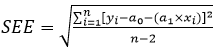 (106)
(106)
The coefficient of determination shall be calculated as follows:
 (107)
(107)
A.3.3. Determination of system equivalency
The determination of system equivalency according to paragraph 5.1.1. of this annex shall be based on a seven sample pair (or larger) correlation study between the candidate system and one of the accepted reference systems of this annex using the appropriate test cycle(s). The equivalency criteria to be applied shall be the F-test and the two-sided Student t-test.
This statistical method examines the hypothesis that the sample standard deviation and sample mean value for an emission measured with the candidate system do not differ from the sample standard deviation and sample mean value for that emission measured with the reference system. The hypothesis shall be tested on the basis of a 10 per cent significance level of the F and t values. The critical F and t values for seven to ten sample pairs are given in Table 9. If the F and t values calculated according to the equation below are greater than the critical F and t values, the candidate system is not equivalent.
The following procedure shall be followed. The subscripts R and C refer to the reference and candidate system, respectively:
(a) Conduct at least seven tests with the candidate and reference systems operated in parallel. The number of tests is referred to as nR and nC;
(b) Calculate the mean values  and
and  and the standard deviations sR and sC;
(c) Calculate the F value, as follows:
 (108)
(108)
(the greater of the two standard deviations sR or sC shall be in the numerator);
(d) Calculate the t value, as follows:
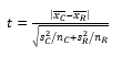 (109)
(109)
(e) Compare the calculated F and t values with the critical F and t values corresponding to the respective number of tests indicated in Table 9. If larger sample sizes are selected, consult statistical tables for 10 per cent significance (90 per cent confidence) level;
(f) Determine the degrees of freedom (df), as follows:
For the F-test: df1 = nR –1, df2 = nC –1 (110)
For the t-test: df = (nC + nR –2)/2 (111)
(g) Determine the equivalency, as follows:
(i) If F < Fcrit and t < tcrit, then the candidate system is equivalent to the reference system of this annex;
(ii) If F Fcrit or t tcrit , then the candidate system is different from the reference system of this annex.
Table 9
t and F values for selected sample sizes
Sample Size | F-test | | t-test | |
| df | Fcrit | df | tcrit |
7 | 6, 6 | 3.055 | 6 | 1.943 |
8 | 7, 7 | 2.785 | 7 | 1.895 |
9 | 8, 8 | 2.589 | 8 | 1.860 |
10 | 9, 9 | 2.440 | 9 | 1.833 |
Annex 4 ‑ Appendix 4 Carbon flow check
A.4.1. Introduction
All but a tiny part of the carbon in the exhaust comes from the fuel, and all but a minimal part of this is manifest in the exhaust gas as CO2. This is the basis for a system verification check based on CO2 measurements.
The flow of carbon into the exhaust measurement systems is determined from the fuel flow rate. The flow of carbon at various sampling points in the emissions and particulate sampling systems is determined from the CO2 concentrations and gas flow rates at those points.
In this sense, the engine provides a known source of carbon flow, and observing the same carbon flow in the exhaust pipe and at the outlet of the partial flow PM sampling system verifies leak integrity and flow measurement accuracy. This check has the advantage that the components are operating under actual engine test conditions of temperature and flow.
Figure 18 shows the sampling points at which the carbon flows shall be checked. The specific equations for the carbon flows at each of the sample points are given below.
Figure 18
Measuring points for carbon flow check

A.4.2. Carbon flow rate into the engine (location 1)
The carbon mass flow rate into the engine for a fuel CHO is given by:
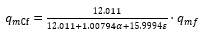 (112)
(112)
Where:
qmf is the fuel mass flow rate, kg/s
A.4.3. Carbon flow rate in the raw exhaust (location 2)
The carbon mass flow rate in the exhaust pipe of the engine shall be determined from the raw CO2 concentration and the exhaust gas mass flow rate:
 (113)
(113)
Where:
cCO2,r is the wet CO2 concentration in the raw exhaust gas, per cent
cCO2,a is the wet CO2 concentration in the ambient air, per cent
qmew is the exhaust gas mass flow rate on wet basis, kg/s
Me is the molar mass of exhaust gas, g/mol
If CO2 is measured on a dry basis it shall be converted to a wet basis according to paragraph 8.1. of this annex.
A.4.4. Carbon flow rate in the dilution system (location 3)
For the partial flow dilution system, the splitting ratio also needs to be taken into account. The carbon flow rate shall be determined from the dilute CO2 concentration, the exhaust gas mass flow rate and the sample flow rate:
 (114)
(114)
Where:
cCO2,d is the wet CO2 concentration in the dilute exhaust gas at the outlet of the dilution tunnel, per cent
cCO2,a is the wet CO2 concentration in the ambient air, per cent
qmew is the exhaust gas mass flow rate on wet basis, kg/s
qmp is the sample flow of exhaust gas into partial flow dilution system, kg/s
Me is the molar mass of exhaust gas, g/mol
If CO2 is measured on a dry basis, it shall be converted to wet basis according to paragraph 8.1. of this annex.
A.4.5. Calculation of the molar mass of the exhaust gas
The molar mass of the exhaust gas shall be calculated according to equation 41 (see paragraph 8.4.2.4. of this annex).
Alternatively, the following exhaust gas molar masses may be used:
Me (diesel) = 28.9 g/mol
Me (LPG) = 28.6 g/mol
Me (NG) = 28.3 g/mol
Annex 4 ‑ Appendix 5 Example of calculation procedure
A.5.1. Speed and torque denormalization procedure
As an example, the following test point shall be denormalized:
per cent speed = 43 per cent
per cent torque = 82 per cent
Given the following values:
nlo = 1,015 min-1
nhi = 2,200 min-1
npref = 1,300 min-1
nidle = 600 min-1
results in:
 With the maximum torque of 700 Nm observed from the mapping curve at 1,178 min-1
A.5.2. Basic data for stoichiometric calculations
Atomic mass of hydrogen 1.00794 g/atom
Atomic mass of carbon 12.011 g/atom
Atomic mass of sulphur 32.065 g/atom
Atomic mass of nitrogen 14.0067 g/atom
Atomic mass of oxygen 15.9994 g/atom
Atomic mass of argon 39.9 g/atom
Molar mass of water 18.01534 g/mol
Molar mass of carbon dioxide 44.01 g/mol
Molar mass of carbon monoxide 28.011 g/mol
Molar mass of oxygen 31.9988 g/mol
Molar mass of nitrogen 28.011 g/mol
Molar mass of nitric oxide 30.008 g/mol
Molar mass of nitrogen dioxide 46.01 g/mol
Molar mass of sulphur dioxide 64.066 g/mol
Molar mass of dry air 28.965 g/mol
Assuming no compressibility effects, all gases involved in the engine intake/combustion/exhaust process can be considered to be ideal and any volumetric calculations shall therefore be based on a molar volume
of 22.414 l/mol according to Avogadro's hypothesis.
A.5.3. Gaseous emissions (diesel fuel)
The measurement data of an individual point of the test cycle (data sampling rate of 1 Hz) for the calculation of the instantaneous mass emission are shown below. In this example, CO and NOx are measured on a dry basis, HC on a wet basis. The HC concentration is given in propane equivalent (C3) and has to be multiplied by 3 to result in the C1 equivalent. The calculation procedure is identical for the other points of the cycle.
The calculation example shows the rounded intermediate results of the different steps for better illustration. It should be noted that for actual calculation, rounding of intermediate results is not permitted (see paragraph 8. of this annex).
Ta,i
(K) | Ha,i
(g/kg) | Wact
(kWh) | qmew,i
(kg/s) | qmaw,i
(kg/s) | qmf,i
(kg/s) | cHC,i
(ppm) | cCO,i
(ppm) | cNOx,i
(ppm) |
295 | 8.0 | 40 | 0.155 | 0.150 | 0.005 | 10 | 40 | 500 |
The following fuel composition is considered:
Component | Molar ratio | Per cent mass |
H | = 1.8529 | wALF = 13.45 |
C | = 1.0000 | wBET = 86.50 |
S | = 0.0002 | wGAM = 0.050 |
N | = 0.0000 | wDEL = 0.000 |
O | = 0.0000 | wEPS = 0.000 |
Step 1: Dry/wet correction (paragraph 8.1. of this annex):
Equation 16:
kf = 0.55584 × 13.45 – 0.0001083 × 86.5 – 0.0001562 ×0.05 = 0.7382
Equation 13:

Equation 12:
cCO,i (wet) = 40 x 0.9331 = 37.3 ppm
cNOx,i (wet) = 500 x 0.9331 = 466.6 ppm
Step 2: NOx correction for temperature and humidity (paragraph 8.2.1. of this annex):
Equation 23:
Step 3: Calculation of the instantaneous emission of each individual point of the cycle (paragraph 8.4.2.3. of this annex):
Equation 36:
mHC,i = 10 x 3 x 0.155 = 4.650
mCO,i = 37.3 x 0.155 = 5.782
mNox,I = 466.6 x 0.9576 x 0.155 = 69.26
Step 4: Calculation of the mass emission over the cycle by integration of the instantaneous emission values and the u values from Table 5 (paragraph 8.4.2.3. of this annex):
The following calculation is assumed for the WHTC cycle (1,800 s) and the same emission in each point of the cycle.
Equation 36:

Step 5: Calculation of the specific emissions (paragraph 8.6.3. of this annex):
Equation 69:
eHC = 4.01 / 40 = 0.10 g/kWh
eCO= 10.05 / 40 = 0.25 g/kWh
eNOx = 197.72 / 40 = 4.94 g/kWh
A.5.4. Particulate Emission (diesel fuel)
pb,b (kPa) | pb,a (kPa) | Wact (kWh) | qmew,i (kg/s) | qmf,i (kg/s) | qmdw,i (kg/s) | qmdew,i (kg/s) | muncor,b (mg) | muncor,a (mg) | msep (kg) |
99 | 100 | 40 | 0.155 | 0.005 | 0.0015 | 0.0020 | 90.0000 | 91.7000 | 1.515 |
Step 1: Calculation of medf (paragraph 8.4.3.2.2. of this annex):
Equation 48:
Equation 47:
qmedf,I = 0.155 x 4 = 0.620 kg/s
Equation 46:

Step 2: Buoyancy correction of the particulate mass (paragraph 8.3. of this annex):
Before test:
Equation 26:

Equation 25:

After test:
Equation 26:

Equation 25:

Equation 27:
mp = 91.7334 mg – 90.0325 mg = 1.7009 mg
Step 3: Calculation of the particulate mass emission (paragraph 8.4.3.2.2. of this annex):
Equation 45:

Step 4: Calculation of the specific emission (paragraph 8.6.3. of this annex):
Equation 69:
ePM = 1.253 / 40 = 0.031 g/kWh
A.5.5. λ-Shift factor (Sλ)
A.5.5.1. Calculation of the λ-shift factor (Sλ)

Where:
Sλ = λ-shift factor;
inert % = per cent by volume of inert gases in the fuel (i.e. N2, CO2,
He, etc.);
 = per cent by volume of original oxygen in the fuel;
n and m = refer to average CnHm representing the fuel hydrocarbons, i.e:


Where:
CH4 = per cent by volume of methane in the fuel;
C2 = per cent by volume of all C2 hydrocarbons (e.g.: C2H6, C2H4, etc.) in the fuel;
C3 = per cent by volume of all C3 hydrocarbons (e.g.: C3H8, C3H6, etc.) in the fuel;
C4 = per cent by volume of all C4 hydrocarbons (e.g.: C4H10, C4H8, etc.) in the fuel;
C5 = per cent by volume of all C5 hydrocarbons (e.g.: C5H12, C5H10, etc.) in the fuel;
diluent = per cent by volume of dilution gases in the fuel (i.e.: O2*, N2, CO2, He, etc.).
A.5.5.2. Examples for the calculation of the λ-shift factor Sλ:
Example 1: G25: CH4 = 86 per cent, N2 = 14 per cent (by volume)

Example 2: GR: CH4 = 87 per cent, C2H6 = 13 per cent (by vol)

Example 3: USA: CH4 = 89 per cent, C2H6 = 4.5 per cent, C3H8 = 2.3 per cent, C6H14 = 0.2 per cent, O2 = 0.6 per cent, N2 = 4 per cent

Annex 4 ‑Appendix 6 Installation of auxiliaries and equipment for emissions test
Number | Auxiliaries | Fitted for emission test |
1 | Inlet system | |
| Inlet manifold | Yes |
| Crankcase emission control system | Yes |
| Control devices for dual induction inlet manifold system | Yes |
| Air flow meter | Yes |
| Air inlet duct work | Yes, or test cell equipment |
| Air filter | Yes, or test cell equipment |
| Inlet silencer | Yes, or test cell equipment |
| Speed-limiting device | Yes |
2 | Induction-heating device of inlet manifold | Yes, if possible to be set in the most favourable condition |
3 | Exhaust system | |
| Exhaust manifold | Yes |
| Connecting pipes | Yes |
| Silencer | Yes |
| Tail pipe | Yes |
| Exhaust brake | No, or fully open |
| Pressure charging device | Yes |
4 | Fuel supply pump | Yes |
5 | Equipment for gas engines | |
| Electronic control system, air flow meter, etc. | Yes |
| Pressure reducer | Yes |
| Evaporator | Yes |
| Mixer | Yes |
6 | Fuel injection equipment | |
| Prefilter | Yes |
| Filter | Yes |
| Pump | Yes |
| High-pressure pipe | Yes |
| Injector | Yes |
| Air inlet valve | Yes |
| Electronic control system, sensors, etc. | Yes |
| Governor/control system | Yes |
| Automatic full-load stop for the control rack depending on atmospheric conditions | Yes |
Number | Auxiliaries | Fitted for emission test |
7 | Liquid-cooling equipment | |
| Radiator | No |
| Fan | No |
| Fan cowl | No |
| Water pump | Yes |
| Thermostat | Yes, may be fixed fully open |
8 | Air cooling | |
| Cowl | No |
| Fan or Blower | No |
| Temperature-regulating device | No |
9 | Electrical equipment | |
| Generator | No |
| Coil or coils | Yes |
| Wiring | Yes |
| Electronic control system | Yes |
10 | Intake air charging equipment | |
| Compressor driven either directly by the engine and/or by the exhaust gases | Yes |
| Charge air cooler | Yes, or test cell system |
| Coolant pump or fan (engine-driven) | No |
| Coolant flow control device | Yes |
11 | Anti-pollution device (exhaust after-treatment system) | Yes |
12 | Starting equipment | Yes, or test cell system |
13 | Lubricating oil pump | Yes |
Annex 4 ‑ Appendix 7 Procedure for the measurement of ammonia
A.7.1. This appendix describes the procedure for measurement of ammonia (NH3). For non-linear analysers, the use of linearising circuits shall be permitted.
A.7.2. Two measurement principles are specified for NH3 measurement and either principle may be used provided it meets the criteria specified in paragraph A.7.2.1. or A.7.2.2., respectively. Gas dryers shall not be permitted for NH3 measurement.
A.7.2.1. Laser Diode Spectrometer (LDS)
A.7.2.1.1. Measurement principle
The LDS employs the single line spectroscopy principle. The NH3 absorption line is chosen in the near infrared spectral range and scanned by a single-mode diode laser.
A.7.2.1.2. Installation
The analyser shall be installed either directly in the exhaust pipe (in-situ) or within an analyser cabinet using extractive sampling in accordance with the instrument manufacturers instructions. If installed in an analyser cabinet, the sample path (sampling line, pre-filter(s) and valves) shall be made of stainless steel or PTFE and shall be heated to 463 ± 10 K (190 ± 10 °C) in order to minimize NH3 losses and sampling artefacts. In addition, the sampling line shall be as short as practically possible.
Influence from exhaust temperature and pressure, installation environment and vibrations on the measurement shall be minimized, or compensation techniques be used.
If applicable, sheath air used in conjunction with in-situ measurement for protection of the instrument, shall not affect the concentration of any exhaust component measured downstream of the device, or sampling of other exhaust components shall be made upstream of the device.
A.7.2.1.3. Cross interference
The spectral resolution of the laser shall be within 0.5 cm-1 in order to minimize cross interference from other gases present in the exhaust gas.
A.7.2.2. Fourier Transform Infrared (hereinafter FTIR) analyser
A.7.2.2.1. Measurement principle
The FTIR employs the broad waveband infrared spectroscopy principle. It allows simultaneous measurement of exhaust components whose standardized spectra are available in the instrument. The absorption spectrum (intensity/wavelength) is calculated from the measured interferogram (intensity/time) by means of the Fourier transform method.
A.7.2.2.2. Installation and sampling
The FTIR shall be installed in accordance with the instrument manufacturer's instructions. The NH3 wavelength shall be selected for evaluation. The sample path (sampling line, pre-filter(s) and valves) shall be made of stainless steel or PTFE and shall be heated to 463 ± 10 K (190 ± 10 °C) in order to minimize NH3 losses and sampling artefacts. In addition, the sampling line shall be as short as practically possible.
A.7.2.2.3. Cross interference
The spectral resolution of the NH3 wavelength shall be within 0.5 cm-1 in order to minimize cross interference from other gases present in the exhaust gas.
A.7.3. Emissions test procedure and evaluation
A.7.3.1. Checking the analysers
Prior to the emissions test, the analyser range shall be selected. Emission analysers with automatic or manual range switching shall be permitted. During the test cycle, the range of the analysers shall not be switched.
Zero and span response shall be determined, if the provisions of paragraph A.7.3.4.2. do not apply for the instrument. For the span response, a NH3 gas that meets the specifications of paragraph A.7.4.2.7. shall be used. The use of reference cells that contain NH3 span gas is permitted.
A.7.3.2. Collection of emission relevant data
At the start of the test sequence, the NH3 data collection shall be started, simultaneously. The NH3 concentration shall be measured continuously and stored with at least 1 Hz on a computer system.
A.7.3.3. Operations after test
At the completion of the test, sampling shall continue until system response times have elapsed. Determination of analyser's drift according to paragraph A.7.3.4.1. shall only be required if the information in paragraph A.7.3.4.2. is not available.
A.7.3.4. Analyser drift
A.7.3.4.1. As soon as practical but no later than 30 minutes after the test cycle is complete or during the soak period, the zero and span responses of the analyser shall be determined. The difference between the pre-test and post-test results shall be less than 2 per cent of full scale.
A.7.3.4.2. Determination of analyser drift is not required in the following situations:
(a) If the zero and span drift specified by the instrument manufacturer in paragraphs A.7.4.2.3. and A.7.4.2.4. meets the requirements of paragraph A.7.3.4.1.,
(b) The time interval for zero and span drift specified by the instrument manufacturer in paragraphs A.7.4.2.3. and A.7.4.2.4. exceeds the duration of the test.
A.7.3.5. Data evaluation
The average NH3 concentration (ppm/test) shall be determined by integrating the instantaneous values over the cycle. The following equation shall be applied:
 (115)
(115)
Where:
cNH3,I is the instantaneous NH3 concentration in the exhaust gas, ppm
n is the number of measurements
For the WHTC, the final test result shall be determined with the following equation:
 (116)
(116)
Where:
cNH3,cold is the average NH3 concentration of the cold start test, ppm
cNH3,hot is the average NH3 concentration of the hot start test, ppm
A.7.4. Analyser specification and verification
A.7.4.1. Linearity requirements
The analyser shall comply with the linearity requirements specified in Table 7 of this annex. The linearity verification in accordance with paragraph 9.2.1. of this annex, shall be performed at least every 12 months or whenever a system repair or change is made that could influence calibration. With the prior approval of the Type Approval Authority, less than 10 reference points are permitted, if an equivalent accuracy can be demonstrated.
For the linearity verification, a NH3 gas that meets the specifications of paragraph A.7.4.2.7. shall be used. The use of reference cells that contain NH3 span gas shall be permitted.
Instruments, whose signals are used for compensation algorithms, shall meet the linearity requirements specified in Table 7 of this annex. Linearity verification shall be done as required by internal audit procedures, by the instrument manufacturer or in accordance with ISO 9000 requirements.
A.7.4.2. Analyser specifications
The analyser shall have a measuring range and response time appropriate for the accuracy required to measure the concentration of NH3 under transient and steady state conditions.
A.7.4.2.1. Minimum detection limit
The analyser shall have a minimum detection limit of < 2 ppm under all conditions of testing.
A.7.4.2.2. Accuracy
The accuracy, defined as the deviation of the analyser reading from the reference value, shall not exceed ± 3 per cent of the reading or ± 2 ppm, whichever is larger.
A.7.4.2.3. Zero drift
The drift of the zero response and the related time interval shall be specified by the instrument manufacturer.
A.7.4.2.4. Span drift
The drift of the span response and the related time interval shall be specified by the instrument manufacturer.
A.7.4.2.5. System response time
The system response time shall be 20 s.
A.7.4.2.6. Rise time
The rise time of the analyser shall be 5 s.
A.7.4.2.7. NH3 calibration gas
A gas mixture with the following chemical composition shall be available.
NH3 and purified nitrogen.
The true concentration of the calibration gas shall be within ±3 per cent of the nominal value. The concentration of NH3 shall be given on a volume basis (volume per cent or volume ppm).
The expiration date of the calibration gases stated by the manufacturer shall be recorded.
A.7.5. Alternative systems
Other systems or analysers may be approved by the Type Approval Authority, if it is found that they yield equivalent results in accordance with paragraph 5.1.1. of this annex.
"Results" shall refer to average cycle specific NH3 concentrations.
Annex 4 ‑ Appendix 8 Particle number emissions measurement equipment
A.8.1. Specification
A.8.1.1. System overview
A.8.1.1.1. The particle sampling system shall consist of a probe or sampling point extracting a sample from a homogenously mixed flow in a dilution system as described in Appendix 2 to this annex, paragraph A.2.2.1. and A.2.2.2. or A.2.2.3. and A.2.2.4., a volatile particle remover (VPR) upstream of a particle number counter (PNC) and suitable transfer tubing.
A.8.1.1.2. It is recommended that a particle size pre-classifier (e.g. cyclone, impactor, etc.) be located prior to the inlet of the VPR. However, a sample probe acting as an appropriate size-classification device, such as that shown in Appendix 2 to this annex, Figure 14, is an acceptable alternative to the use of a particle size pre-classifier. In the case of partial flow dilution systems it is acceptable to use the same pre-classifier for particulate mass and particle number sampling, extracting the particle number sample from the dilution system downstream of the pre-classifier. Alternatively separate pre-classifiers may be used, extracting the particle number sample from the dilution system upstream of the particulate mass pre-classifier.
A.8.1.2. General requirements
A.8.1.2.1. The particle sampling point shall be located within a dilution system.
The sampling probe tip or particle sampling point and particle transfer tube (PTT) together comprise the particle transfer system (PTS). The PTS conducts the sample from the dilution tunnel to the entrance of the VPR. The PTS shall meet the following conditions:
In the case of full flow dilution systems and partial flow dilution systems of the fractional sampling type (as described in Appendix 2 to this annex, paragraph A.2.2.1.) the sampling probe shall be installed near the tunnel centre line, 10 to 20 tunnel diameters downstream of the gas inlet, facing upstream into the tunnel gas flow with its axis at the tip parallel to that of the dilution tunnel. The sampling probe shall be positioned within the dilution tract so that the sample is taken from a homogeneous diluent/exhaust mixture.
In the case of partial flow dilution systems of the total sampling type (as described in Appendix 2 to this annex, paragraph A.2.2.1.) the particle sampling point or sampling probe shall be located in the particulate transfer tube, upstream of the particulate filter holder, flow measurement device and any sample/bypass bifurcation point. The sampling point or sampling probe shall be positioned so that the sample is taken from a homogeneous diluent/exhaust mixture. The dimensions of the particle sampling probe should be sized not to interfere with the operation of the partial flow dilution system.
Sample gas drawn through the PTS shall meet the following conditions:
In the case of full flow dilution systems, it shall have a flow Reynolds number (Re) of < 1,700;
In the case of partial flow dilution systems, it shall have a flow Reynolds number (Re) of < 1,700 in the PTT i.e. downstream of the sampling probe or point;
It shall have a residence time in the PTS of ≤ 3 seconds.
Any other sampling configuration for the PTS for which equivalent particle penetration at 30 nm can be demonstrated will be considered acceptable.
The outlet tube (OT) conducting the diluted sample from the VPR to the inlet of the PNC shall have the following properties:
It shall have an internal diameter of ≥ 4 mm;
Sample Gas flow through the OT shall have a residence time of ≤ 0.8 second.
Any other sampling configuration for the OT for which equivalent particle penetration at 30 nm can be demonstrated will be considered acceptable.
A.8.1.2.2. The VPR shall include devices for sample dilution and for volatile particle removal.
A.8.1.2.3. All parts of the dilution system and the sampling system from the exhaust pipe up to the PNC, which are in contact with raw and diluted exhaust gas, shall be designed to minimize deposition of the particles. All parts shall be made of electrically conductive materials that do not react with exhaust gas components, and shall be electrically grounded to prevent electrostatic effects.
A.8.1.2.4. The particle sampling system shall incorporate good aerosol sampling practice that includes the avoidance of sharp bends and abrupt changes in cross-paragraph, the use of smooth internal surfaces and the minimisation of the length of the sampling line. Gradual changes in the cross-section are permissible.
A.8.1.3. Specific requirements
A.8.1.3.1. The particle sample shall not pass through a pump before passing through the PNC.
A.8.1.3.2. A sample pre-classifier is recommended.
A.8.1.3.3. The sample preconditioning unit shall:
A.8.1.3.3.1. Be capable of diluting the sample in one or more stages to achieve a particle number concentration below the upper threshold of the single particle count mode of the PNC and a gas temperature below 35 °C at the inlet to the PNC;
A.8.1.3.3.2. Include an initial heated dilution stage which outputs a sample at a temperature of 150 °C and ≤ 400 °C, and dilutes by a factor of at least 10;
A.8.1.3.3.3. Control heated stages to constant nominal operating temperatures, within the range specified in paragraph A.8.1.3.3.2., to a tolerance of ±10 °C. Provide an indication of whether or not heated stages are at their correct operating temperatures;
A.8.1.3.3.4. Achieve a particle concentration reduction factor (fr(di)), as defined in paragraph A.8.2.2.2. below, for particles of 30 nm and 50 nm electrical mobility diameters, that is no more than 30 per cent and 20 per cent respectively higher, and no more than 5 per cent lower than that for particles of 100 nm electrical mobility diameter for the VPR as a whole;
A.8.1.3.3.5. Also achieve > 99.0 per cent vaporisation of 30 nm tetracontane (CH3(CH2)38CH3) particles, with an inlet concentration of ≥ 10,000 cm-3, by means of heating and reduction of partial pressures of the tetracontane.
A.8.1.3.4. The PNC shall:
A.8.1.3.4.1. Operate under full flow operating conditions;
A.8.1.3.4.2. Have a counting accuracy of ± 10 per cent across the range 1 cm-3 to the upper threshold of the single particle count mode of the PNC against a traceable standard. At concentrations below 100 cm-3 measurements averaged over extended sampling periods may be required to demonstrate the accuracy of the PNC with a high degree of statistical confidence;
A.8.1.3.4.3. Have a readability of at least 0.1 particle cm-3 at concentrations below 100 cm- 3;
A.8.1.3.4.4. Have a linear response to particle concentrations over the full measurement range in single particle count mode;
A.8.1.3.4.5. Have a data reporting frequency equal to or greater than 0.5 Hz;
A.8.1.3.4.6. Have a t90 response time over the measured concentration range of less than 5 s;
A.8.1.3.4.7. Incorporate a coincidence correction function up to a maximum 10 per cent correction, and may make use of an internal calibration factor as determined in paragraph A.8.2.1.3., but shall not make use of any other algorithm to correct for or define the counting efficiency;
A.8.1.3.4.8. Have counting efficiencies at particle sizes of 23 nm (±1 nm) and 41 nm (±1 nm) electrical mobility diameter of 50 per cent (±12 per cent) and > 90 per cent respectively. These counting efficiencies may be achieved by internal (for example; control of instrument design) or external (for example; size pre-classification) means;
A.8.1.3.4.9. If the PNC makes use of a working liquid, it shall be replaced at the frequency specified by the instrument manufacturer.
A.8.1.3.5. Where they are not held at a known constant level at the point at which PNC flow rate is controlled, the pressure and/or temperature at inlet to the PNC shall be measured and reported for the purposes of correcting particle concentration measurements to standard conditions.
A.8.1.3.6. The sum of the residence time of the PTS, VPR and OT plus the t90 response time of the PNC shall be no greater than 20 s.
A.8.1.3.7. The transformation time of the entire particle number sampling system (PTS, VPR, OT and PNC) shall be determined by aerosol switching directly at the inlet of the PTS. The aerosol switching shall be done in less than 0.1 s. The aerosol used for the test shall cause a concentration change of at least 60 per cent full scale (FS).
The concentration trace shall be recorded. For time alignment of the particle number concentration and exhaust flow signals, the transformation time is defined as the time from the change (t0) until the response is 50 per cent of the final reading (t50).
A.8.1.4. Recommended system description
The following paragraph contains the recommended practice for measurement of particle number. However, any system meeting the performance specifications in paragraphs A.8.1.2. and A.8.1.3. is acceptable.
Figures 19 and 20 are schematic drawings of the recommended particle sampling system configures for partial and full flow dilution systems respectively.
Figure 19
Schematic of recommended particle sampling system – Partial flow sampling
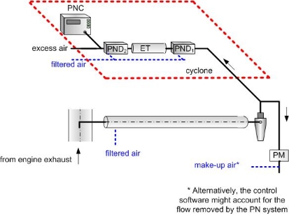
Figure 20
Schematic of recommended particle sampling system – Full flow sampling

A.8.1.4.1. Sampling system description
The particle sampling system shall consist of a sampling probe tip or particle sampling point in the dilution system, a particle transfer tube (PTT), a particle pre-classifier (PCF) and a volatile particle remover (VPR) upstream of the particle number concentration measurement (PNC) unit. The VPR shall include devices for sample dilution (particle number diluters: PND1 and PND2) and particle evaporation (Evaporation tube, ET). The sampling probe or sampling point for the test gas flow shall be so arranged within the dilution tract that a representative sample gas flow is taken from a homogeneous diluent/exhaust mixture. The sum of the residence time of the system plus the t90 response time of the PNC shall be no greater than 20 s.
A.8.1.4.2. Particle transfer system
The sampling probe tip or particle sampling point and Particle Transfer Tube (PTT) together comprise the Particle Transfer System (PTS). The PTS conducts the sample from the dilution tunnel to the entrance to the first particle number diluter. The PTS shall meet the following conditions:
In the case of full flow dilution systems and partial flow dilution systems of the fractional sampling type (as described in Appendix 2 to this annex, paragraph A.2.2.1.) the sampling probe shall be installed near the tunnel centre line, 10 to 20 tunnel diameters downstream of the gas inlet, facing upstream into the tunnel gas flow with its axis at the tip parallel to that of the dilution tunnel. The sampling probe shall be positioned within the dilution tract so that the sample is taken from a homogeneous diluent/exhaust mixture.
In the case of partial flow dilution systems of the total sampling type (as described in Appendix 2 to this annex, paragraph A.2.2.1.) the particle sampling point shall be located in the particulate transfer tube, upstream of the particulate filter holder, flow measurement device and any sample/bypass bifurcation point. The sampling point or sampling probe shall be positioned so that the sample is taken from a homogeneous diluent/exhaust mixture.
Sample gas drawn through the PTS shall meet the following conditions:
It shall have a flow Reynolds number (Re) of < 1,700;
It shall have a residence time in the PTS of ≤ 3 seconds.
Any other sampling configuration for the PTS for which equivalent particle penetration for particles of 30 nm electrical mobility diameter can be demonstrated will be considered acceptable.
The outlet tube (OT) conducting the diluted sample from the VPR to the inlet of the PNC shall have the following properties:
It shall have an internal diameter of ≥ 4 mm;
Sample gas flow through the POT shall have a residence time of ≤ 0.8 second.
Any other sampling configuration for the OT for which equivalent particle penetration for particles of 30 nm electrical mobility diameter can be demonstrated will be considered acceptable.
A.8.1.4.3. Particle pre-classifier
The recommended particle pre-classifier shall be located upstream of the VPR. The pre-classifier 50 per cent cut point particle diameter shall be between 2.5 µm and 10 µm at the volumetric flow rate selected for sampling particle number emissions. The pre-classifier shall allow at least 99 per cent of the mass concentration of 1 µm particles entering the pre-classifier to pass through the exit of the pre-classifier at the volumetric flow rate selected for sampling particle number emissions. In the case of partial flow dilution systems, it is acceptable to use the same pre-classifier for particulate mass and particle number sampling, extracting the particle number sample from the dilution system downstream of the pre-classifier. Alternatively separate pre-classifiers may be used, extracting the particle number sample from the dilution system upstream of the particulate mass pre-classifier.
A.8.1.4.4. Volatile particle remover (VPR)
The VPR shall comprise one particle number diluter (PND1), an evaporation tube and a second diluter (PND2) in series. This dilution function is to reduce the number concentration of the sample entering the particle concentration measurement unit to less than the upper threshold of the single particle count mode of the PNC and to suppress nucleation within the sample. The VPR shall provide an indication of whether or not PND1 and the evaporation tube are at their correct operating temperatures.
The VPR shall achieve > 99.0 per cent vaporisation of 30 nm tetracontane (CH3(CH2)38CH3) particles, with an inlet concentration of ≥ 10,000 cm-3, by means of heating and reduction of partial pressures of the tetracontane. It shall also achieve a particle concentration reduction factor (fr) for particles of 30 nm and 50 nm electrical mobility diameters, that is no more than 30 per cent and 20 per cent respectively higher, and no more than 5 per cent lower than that for particles of 100 nm electrical mobility diameter for the VPR as a whole.
A.8.1.4.4.1. First particle number dilution device (PND1)
The first particle number dilution device shall be specifically designed to dilute particle number concentration and operate at a (wall) temperature of 150 °C to 400 °C. The wall temperature setpoint should be held at a constant nominal operating temperature, within this range, to a tolerance of ±10 °C and not exceed the wall temperature of the ET (paragraph A.8.1.4.4.2.). The diluter should be supplied with HEPA filtered dilution air and be capable of a dilution factor of 10 to 200 times.
A.8.1.4.4.2. Evaporation Tube (ET)
The entire length of the ET shall be controlled to a wall temperature greater than or equal to that of the first particle number dilution device and the wall temperature held at a fixed nominal operating temperature between 300 °C and 400 °C, to a tolerance of ±10 °C.
A.8.1.4.4.3. Second particle number dilution device (PND2)
PND2 shall be specifically designed to dilute particle number concentration. The diluter shall be supplied with HEPA filtered dilution air and be capable of maintaining a single dilution factor within a range of 10 to 30 times. The dilution factor of PND2 shall be selected in the range between 10 and 15 such that particle number concentration downstream of the second diluter is less than the upper threshold of the single particle count mode of the PNC and the gas temperature prior to entry to the PNC is < 35 °C.
A.8.1.4.5. Particle number counter (PNC)
The PNC shall meet the requirements of paragraph A.8.1.3.4.
A.8.2. Calibration/Validation of the particle sampling system
A.8.2.1. Calibration of the particle number counter
A.8.2.1.1. The Technical Service shall ensure the existence of a calibration certificate for the PNC demonstrating compliance with a traceable standard within a
12-month period prior to the emissions test.
A.8.2.1.2. The PNC shall also be recalibrated and a new calibration certificate issued following any major maintenance.
A.8.2.1.3. Calibration shall be traceable to a standard calibration method:
(a) By comparison of the response of the PNC under calibration with that of a calibrated aerosol electrometer when simultaneously sampling electrostatically classified calibration particles; or
(b) By comparison of the response of the PNC under calibration with that of a second PNC which has been directly calibrated by the above method.
In the electrometer case, calibration shall be undertaken using at least six standard concentrations spaced as uniformly as possible across the PNC’s measurement range. These points will include a nominal zero concentration point produced by attaching HEPA filters of at least class H13 of EN 1822:2008, or equivalent performance, to the inlet of each instrument. With no calibration factor applied to the PNC under calibration, measured concentrations shall be within ±10 per cent of the standard concentration for each concentration used, with the exception of the zero point, otherwise the PNC under calibration shall be rejected. The gradient from a linear regression of the two data sets shall be calculated and recorded. A calibration factor equal to the reciprocal of the gradient shall be applied to the PNC under calibration. Linearity of response is calculated as the square of the Pearson product moment correlation coefficient (R2) of the two data sets and shall be equal to or greater than 0.97. In calculating both the gradient and R2 the linear regression shall be forced through the origin (zero concentration on both instruments).
In the reference PNC case, calibration shall be undertaken using at least six standard concentrations across the PNC’s measurement range. At least 3 points shall be at concentrations below 1,000 cm-3, the remaining concentrations shall be linearly spaced between 1,000 cm-3 and the maximum of the PNC’s range in single particle count mode. These points will include a nominal zero concentration point produced by attaching HEPA filters of at least class H13 of EN 1822:2008, or equivalent performance, to the inlet of each instrument. With no calibration factor applied to the PNC under calibration, measured concentrations shall be within ±10 per cent of the standard concentration for each concentration, with the exception of the zero point, otherwise the PNC under calibration shall be rejected. The gradient from a linear regression of the two data sets shall be calculated and recorded. A calibration factor equal to the reciprocal of the gradient shall be applied to the PNC under calibration. Linearity of response is calculated as the square of the Pearson product moment correlation coefficient (R2) of the two data sets and shall be equal to or greater than 0.97. In calculating both the gradient and R2 the linear regression shall be forced through the origin (zero concentration on both instruments).
A.8.2.1.4. Calibration shall also include a check, against the requirements in paragraph A.8.1.3.4.8., on the PNC’s detection efficiency with particles of 23 nm electrical mobility diameter. A check of the counting efficiency with 41 nm particles is not required.
A.8.2.2. Calibration/Validation of the volatile particle remover
A.8.2.2.1. Calibration of the VPR’s particle concentration reduction factors across its full range of dilution settings, at the instrument’s fixed nominal operating temperatures, shall be required when the unit is new and following any major maintenance. The periodic validation requirement for the VPR’s particle concentration reduction factor is limited to a check at a single setting, typical of that used for measurement on diesel particulate filter equipped vehicles. The Technical Service shall ensure the existence of a calibration or validation certificate for the volatile particle remover within a 6-month period prior to the emissions test. If the volatile particle remover incorporates temperature monitoring alarms a 12 month validation interval shall be permissible.
The VPR shall be characterised for particle concentration reduction factor with solid particles of 30 nm, 50 nm and 100 nm electrical mobility diameter. Particle concentration reduction factors (fr(d)) for particles of 30 nm and 50 nm electrical mobility diameters shall be no more than 30 per cent and 20 per cent higher respectively, and no more than 5 per cent lower than that for particles of 100 nm electrical mobility diameter. For the purposes of validation, the mean particle concentration reduction factor shall be within ±10 per cent of the mean particle concentration reduction factor ( ) determined during the primary calibration of the VPR.
A.8.2.2.2. The test aerosol for these measurements shall be solid particles of 30, 50 and 100 nm electrical mobility diameter and a minimum concentration of 5,000 particles cm-3 at the VPR inlet. Particle concentrations shall be measured upstream and downstream of the components.
The particle concentration reduction factor at each particle size (fr(di) ) shall be calculated as follows:
 (117)
(117)
Where:
Nin(di) = upstream particle number concentration for particles of diameter di
Nout(di) = downstream particle number concentration for particles of diameter di and
di = particle electrical mobility diameter (30, 50 or 100 nm)
Nin(di) and Nout(di) shall be corrected to the same conditions.
The mean particle concentration reduction () at a given dilution setting shall be calculated as follows:
 (118)
(118)
It is recommended that the VPR is calibrated and validated as a complete unit.
A.8.2.2.3. The Technical Service shall ensure the existence of a validation certificate for the VPR demonstrating effective volatile particle removal efficiency within a 6 month period prior to the emissions test. If the volatile particle remover incorporates temperature monitoring alarms a 12 month validation interval shall be permissible. The VPR shall demonstrate greater than 99.0 per cent removal of tetracontane (CH3(CH2)38CH3) particles of at least 30 nm electrical mobility diameter with an inlet concentration of ≥ 10,000 cm-3 when operated at its minimum dilution setting and manufacturers recommended operating temperature.
A.8.2.3. Particle number system check procedures
A.8.2.3.1. Prior to each test, the particle counter shall report a measured concentration of less than 0.5 particles cm-3 when a HEPA filter of at least class H13 of EN 1822:2008, or equivalent performance, is attached to the inlet of the entire particle sampling system (VPR and PNC).
A.8.2.3.2. On a monthly basis, the flow into the particle counter shall report a measured value within 5 per cent of the particle counter nominal flow rate when checked with a calibrated flow meter.
A.8.2.3.3. Each day, following the application of a HEPA filter of at least class H13 of EN 1822:2008, or equivalent performance, to the inlet of the particle counter, the particle counter shall report a concentration of ≤ 0.2 cm-3. Upon removal of this filter, the particle counter shall show an increase in measured concentration to at least 100 particles cm-3 when challenged with ambient air and a return to ≤ 0.2 cm-3 on replacement of the HEPA filter.
A.8.2.3.4. Prior to the start of each test it shall be confirmed that the measurement system indicates that the evaporation tube, where featured in the system, has reached its correct operating temperature.
A.8.2.3.5. Prior to the start of each test it shall be confirmed that the measurement system indicates that the diluter PND1 has reached its correct operating temperature.
Annex 5 Specifications of reference fuels
Technical data on fuels for testing compression-ignition and dual-fuel engines
Type: Diesel (B7)
Parameter | Unit | Limit1 | Test method |
Minimum | Maximum |
Cetane index | | 46.0 | | EN ISO 4264 |
Cetane number2 | | 52.0 | 56.0 | EN-ISO 5165 |
Density at 15 °C | kg/m3 | 833 | 837 | EN-ISO 3675 EN ISO 12185 |
Distillation: | | | | |
- 50 % point | °C | 245 | | EN-ISO 3405 |
- 95 % point | °C | 345 | 350 | EN-ISO 3405 |
- final boiling point | °C | | 360 | EN-ISO 3405 |
Flash point | °C | 55 | | EN 22719 |
CFPP | °C | | 5 | EN 116 |
Viscosity at 40 °C | mm2/s | 2.3 | 3.3 | EN-ISO 3104 |
Polycyclic aromatic hydrocarbons | % m/m | 2.0 | 4.0 | EN 12916 |
Sulphur content | mg/kg | | 10 | EN ISO 20846 / EN ISO 20884 |
Copper corrosion (3h at 50 °C) | Rating | | Class 1 | EN-ISO 2160 |
Conradson carbon residue (10 % DR) | % m/m | | 0.2 | EN-ISO 10370 |
Ash content | % m/m | | 0.01 | EN-ISO 6245 |
Total contamination | mg/kg | | 24 | EN 12662 |
Water content | % m/m | | 0.02 | EN-ISO 12937 |
Neutralisation (strong acid) number | mg KOH/g | | 0.10 | ASTM D 974 |
Oxidation stability3 | mg/ml | | 0.025 | EN-ISO 12205 |
Lubricity (HFRR wear scan diameter at 60 °C) | µm | | 400 | EN ISO 12156 |
Oxidation stability at 110 °C3 | H | 20.0 | | EN 15751 |
FAME4 | % v/v | 6.0 | 7.0 | EN 14078 |
Notes: 1 The values quoted in the specifications are "true values". In establishment of their limit values the terms of ISO 4259 Petroleum products – Determination and application of precision data in relation to methods of test have been applied and in fixing a minimum value, a minimum difference of 2R above zero has been taken into account; in fixing a maximum and minimum value, the minimum difference is 4R (R = reproducibility). Notwithstanding this measure, which is necessary for technical reasons, the manufacturer of fuels shall nevertheless aim at a zero value where the stipulated maximum value is 2R and at the mean value in the case of quotations of maximum and minimum limits. Should it be necessary to clarify whether a fuel meets the requirements of the specifications, the terms of ISO 4259 shall be applied. 2 The range for cetane number is not in accordance with the requirements of a minimum range of 4R. However, in the case of a dispute between fuel supplier and fuel user, the terms of ISO 4259 may be used to resolve such disputes provided replicate measurements, of sufficient number to archive the necessary precision, are made in preference to single determinations. 3 Even though oxidation stability is controlled, it is likely that shelf life will be limited. Advice shall be sought from the supplier as to storage conditions and life. 4 FAME content to meet the specification of EN 14214. |
Type: Ethanol for dedicated compression ignition engines (ED95)1
Parameter | Unit | Limits2 | Test method3 |
| | Minimum | Maximum |
Total alcohol (Ethanol incl. content on higher saturated alcohols) | % m/m | 92.4 | | EN 15721 |
Other higher saturated mono-alcohols (C3-C5) | % m/m | | 2.0 | EN 15721 |
Methanol | % m/m | | 0.3 | EN 15721 |
Density 15ºC | kg/m3 | 793.0 | 815.0 | EN ISO 12185 |
Acidity, calculated as acetic acid | % m/m | | 0.0025 | EN 15491 |
Appearance | | Bright and clear | |
Flashpoint | ºC | 10 | | EN 3679 |
Dry residue | mg/kg | | 15 | EN 15691 |
Water content | % m/m | | 6.5 | EN 154894 EN-ISO 12937 EN15692 |
Aldehydes calculated as acetaldehyde | % m/m | | 0.0050 | ISO 1388-4 |
Esters calculated as ethylacetat | % m/m | | 0.1 | ASTM D1617 |
Sulphur content | mg/kg | | 10.0 | EN 15485 EN 15486 |
Sulphates | mg/kg | | 4.0 | EN 15492 |
Particulate contamination | mg/kg | | 24 | EN 12662 |
Phosphorus | mg/l | | 0.20 | EN 15487 |
Inorganic chloride | mg/kg | | 1.0 | EN 15484 or EN 15492 |
Copper | mg/kg | | 0.100 | EN 15488 |
Electrical Conductivity | µS/cm | | 2.50 | DIN 51627-4 or prEN 15938 |
Notes: 1 Additives, such as cetane improver as specified by the engine manufacturer, may be added to the ethanol fuel, as long as no negative side effects are known. If these conditions are satisfied, the maximum allowed amount is 10 % m/m. 2 The values quoted in the specifications are "true values". In establishment of their limit values the terms of ISO 4259 Petroleum products – Determination and application of precision data in relation to methods of test have been applied and in fixing a minimum value, a minimum difference of 2R above zero has been taken into account; in fixing a maximum and minimum value, the minimum difference is 4R (R = reproducibility). Notwithstanding this measure, which is necessary for technical reasons, the manufacturer of fuels shall nevertheless aim at a zero value where the stipulated maximum value is 2R and at the mean value in the case of quotations of maximum and minimum limits. Should it be necessary to clarify whether a fuel meets the requirements of the specifications, the terms of ISO 4259 shall be applied. 3 Equivalent EN/ISO methods will be adopted when issued for properties listed above. 4 Should it be necessary to clarify whether a fuel meets the requirements of the specifications, the terms of
EN 15489 shall be applied. |
Technical data on fuels for testing positive ignition and dual-fuel engines
Type: Petrol (E10)
Parameter | Unit | Limits1 | Test method2 |
Minimum | Maximum | |
Research octane number, RON | | 95.0 | 97.0 | EN ISO 5164:20053 |
Motor octane number, MON | | 84.0 | 86.0 | EN ISO 5163:20053 |
Density at 15 °C | kg/m3 | 743 | 756 | EN ISO 3675 EN ISO 12185 |
Vapour pressure | kPa | 56.0 | 60.0 | EN ISO 13016-1 (DVPE) |
Water content | % v/v | | 0.015 | ASTM E 1064 |
Distillation: | | | | |
- evaporated at 70 °C | % v/v | 24.0 | 44.0 | EN-ISO 3405 |
- evaporated at 100 °C | % v/v | 56.0 | 60.0 | EN-ISO 3405 |
- evaporated at 150 °C | % v/v | 88.0 | 90.0 | EN-ISO 3405 |
- final boiling point | °C | 190 | 210 | EN-ISO 3405 |
Residue | % v/v | — | 2.0 | EN-ISO 3405 |
Hydrocarbon analysis: | | | | |
- olefins | % v/v | 3.0 | 18.0 | EN 14517 EN 15553 |
- aromatics | % v/v | 25.0 | 35.0 | EN 14517 EN 15553 |
- benzene | % v/v | 0.4 | 1.0 | EN 12177 EN 238, EN 14517 |
- saturates | % v/v | Report | EN 14517 EN 15553 |
Carbon/hydrogen ratio | | Report | |
Carbon/oxygen ratio | | Report | |
Induction period4 | minutes | 480 | | EN-ISO 7536 |
Oxygen content5 | % m/m | 3.7 | EN 1601 EN 13132 EN 14517 |
Existent gum | mg/ml | — | 0.04 | EN-ISO 6246 |
Sulphur content6 | mg/kg | — | 10 | EN ISO 20846 EN ISO 20884 |
Copper corrosion (3h at 50 °C) | rating | — | Class 1 | EN-ISO 2160 |
Lead content | mg/l | — | 5 | EN 237 |
Phosphorus content7 | mg/l | — | 1.3 | ASTM D 3231 |
Ethanol4 | % v/v | 9.5 | 10.0 | EN 1601 EN 13132 EN 14517 |
Notes: 1 The values quoted in the specifications are "true values". In establishment of their limit values the terms of ISO 4259 Petroleum products - Determination and application of precision data in relation to methods of test have been applied and in fixing a minimum value, a minimum difference of 2R above zero has been taken into account; in fixing a maximum and minimum value, the minimum difference is 4R (R = reproducibility). Notwithstanding this measure, which is necessary for technical reasons, the manufacturer of fuels shall nevertheless aim at a zero value where the stipulated maximum value is 2R and at the mean value in the case of quotations of maximum and minimum limits. Should it be necessary to clarify whether a fuel meets the requirements of the specifications, the terms of ISO 4259 shall be applied. 2 Equivalent EN/ISO methods will be adopted when issued for properties listed above. 3 A correction factor of 0.2 for MON and RON shall be subtracted for the calculation of the final result in accordance with EN 228:2008. 4 The fuel may contain oxidation inhibitors and metal deactivators normally used to stabilise refinery gasoline streams, but detergent/dispersive additives and solvent oils shall not be added. 5 Ethanol meeting the specification of EN 15376 is the only oxygenate that shall be intentionally added to the reference fuel. 6 The actual sulphur content of the fuel used for the Type 1 test shall be reported. 7 There shall be no intentional addition of compounds containing phosphorus, iron, manganese, or lead to this reference fuel. |
Type: Ethanol (E85)
Parameter | Unit | Limits1 | Test method |
Minimum | Maximum |
Research octane number, RON | | 95.0 | — | EN ISO 5164 |
Motor octane number, MON | | 85.0 | — | EN ISO 5163 |
Density at 15 oC | kg/m3 | Report | ISO 3675 |
Vapour pressure | kPa | 40.0 | 60.0 | EN ISO 13016-1 (DVPE) |
Sulphur content2 | mg/kg | — | 10 | EN 15485 or EN 15486 |
Oxidation stability | Minutes | 360 | | EN ISO 7536 |
Existent gum content (solvent washed) | mg/100ml | — | 5 | EN-ISO 6246 |
Appearance
This shall be determined at ambient temperature or 15°C whichever is higher | | Clear and bright, visibly free of suspended or precipitated contaminants | Visual inspection |
Ethanol and higher alcohols3 | % v/v | 83 | 85 | EN 1601 EN 13132 EN 14517 E DIN 51627-3 |
Higher alcohols (C3-C8) | % v/v | — | 2.0 | E DIN 51627-3 |
Methanol | % v/v | | 1.00 | E DIN 51627-3 |
Petrol4 | % v/v | Balance | EN 228 |
Phosphous | mg/l | 0.205 | EN 15487 |
Water content | % v/v | | 0.300 | EN 15489 or EN 15692 |
Inorganic chloride content | mg/l | | 1 | EN 15492 |
pHe | | 6.5 | 9.0 | EN 15490 |
Copper strip corrosion
(3h at 50°C) | Rating | Class 1 | | EN ISO 2160 |
Acidity, (as acetic acid CH3COOH) | % m/m
(mg/l)
| — | 0.0050
(40)
| EN 15491 |
Electric Conductivity | µS/cm | 1.5 | DIN 51627-4 or prEN 15938 |
Carbon/hydrogen ratio | | report | |
Carbon/oxygen ration | | report | |
Notes: 1 The values quoted in the specifications are "true values". In establishment of their limit values the terms of ISO 4259 Petroleum products - Determination and application of precision data in relation to methods of test have been applied and in fixing a minimum value, a minimum difference of 2R above zero has been taken into account; in fixing a maximum and minimum value, the minimum difference is 4R
(R = reproducibility). Notwithstanding this measure, which is necessary for technical reasons, the manufacturer of fuels shall nevertheless aim at a zero value where the stipulated maximum value is 2R and at the mean value in the case of quotations of maximum and minimum limits. Should it be necessary to clarify whether a fuel meets the requirements of the specifications, the terms of ISO 4259 shall be applied. 2 The actual sulphur content of the fuel used for the emission tests shall be reported. 3 Ethanol to meet specification of EN 15376 is the only oxygenate that shall be intentionally added to this reference fuel. 4 The unleaded petrol content can be determined as 100 minus the sum of the percentage content of water, alcohols, MTBE and ETBE. 5 There shall be no intentional addition of compounds containing phosphorus, iron, manganese, or lead to this reference fuel. |
Type: LPG
Parameter | Unit | Fuel A | Fuel B | Test method |
Composition: | | | | EN 27941 |
C3-content | % v/v | 30 ± 2 | 85 ± 2 | |
C4-content | % v/v | Balance1 | Balance1 | |
< C3 , > C4 | % v/v | Maximum 2 | Maximum 2 | |
Olefins | % v/v | Maximum 12 | Maximum 15 | |
Evaporation residue | mg/kg | Maximum 50 | Maximum 50 | EN 15470 |
Water at 0 °C | | Free | Free | EN 15469 |
Total sulphur content including odorant | mg/kg | Maximum 10 | Maximum 10 | EN 24260, ASTM D 3246, ASTM 6667 |
Hydrogen sulphide | | None | None | EN ISO 8819 |
Copper strip corrosion (1h at 40 °C) | Rating | Class 1 | Class 1 | ISO 62512 |
Odour | | Characteristic | Characteristic | |
Motor octane number3 | | Minimum 89.0 | Minimum 89.0 | EN 589 Annex B |
Notes: 1 Balance shall be read as follows: balance = 100 - C3 - <C3 - >C4. 2 This method may not accurately determine the presence of corrosive materials if the sample contains corrosion inhibitors or other chemicals which diminish the corrosivity of the sample to the copper strip. Therefore, the addition of such compounds for the sole purpose of biasing the test method is prohibited. 3 At the request of the engine manufacturer, a higher MON could be used to perform the type approval tests. |
Type: Natural Gas/ Biomethane
Characteristics | Units | Basis | Limits | Test method |
minimum | maximum |
Reference fuel GR |
Composition: | | | | | |
Methane | | 87 | 84 | 89 | |
Ethane | | 13 | 11 | 15 | |
Balance1 | % mole | — | — | 1 | ISO 6974 |
Sulphur content | mg/m3 2 | — | | 10 | ISO 6326-5 |
| | | | | |
Notes: 1 Inerts + C2+ 2 Value to be determined at standard conditions 293.2 K (20 °C) and 101.3 kPa. |
Reference fuel G23 |
Composition: | | | | | |
Methane | | 92.5 | 91.5 | 93.5 | |
Balance1 | % mole | — | — | 1 | ISO 6974 |
N2 | % mole | 7.5 | 6.5 | 8.5 | |
Sulphur content | mg/m3 2 | — | — | 10 | ISO 6326-5 |
| | | | | |
Notes: 1 Inerts (different from N2) + C2+ C2+ 2 Value to be determined at 293.2 K (20 °C) and 101.3 kPa. |
Reference fuel G25 |
Composition: | | | | | |
Methane | % mole | 86 | 84 | 88 | |
Balance1 | % mole | — | — | 1 | ISO 6974 |
N2 | % mole | 14 | 12 | 16 | |
Sulphur content | mg/m3 2 | — | — | 10 | ISO 6326-5 |
| | | | | |
Notes: 1 Inerts (different from N2) + C2+ C2+ 2 Value to be determined at 293.2 K (20 °C) and 101.3 kPa. |
Reference fuel G20 |
Composition: | | | | | |
Methane | % mole | 100 | 99 | 100 | ISO 6974 |
Balance (1) | % mole | — | — | 1 | ISO 6974 |
N2 | % mole | | | | ISO 6974 |
Sulphur content | mg/m3 (2) | — | — | 10 | ISO 6326-5 |
Wobbe Index (net) | MJ/m3 (3) | 48.2 | 47.2 | 49.2 | |
(1) Inerts (different from N2) + C2 + C2+. (2) Value to be determined at 293,2 K (20 °C) and 101,3 kPa. (3) Value to be determined at 273,2 K (0 °C) and 101,3 kPa. |
| | | | | | | | | | |
Annex 6 Emissions data required at type approval for roadworthiness purposes
Measuring carbon monoxide emissions at idling speeds
1. Introduction
1.1. This annex sets out the procedure for measuring carbon monoxide emissions at idling speeds (normal and high) for positive ignition engines installed in vehicles of category M1 with a technically permissible maximum laden mass not exceeding 7.5 tonnes, as well as in vehicles of categories M2 and N1.
1.2. This annex does not apply to dual-fuel engines and vehicles.
2. General requirements
2.1. The general requirements shall be those set out in paragraph 5.3.7. of Regulation No. 83, with the exceptions set out in paragraphs 2.2., 2.3. and 2.4.
2.2. The atomic ratios set out in paragraph 5.3.7.3. of Regulation No. 83 shall be understood as follows:
Hcv = Atomic ratio of hydrogen to carbon | – for petrol (E10) 1.93 – for LPG 2.525 – for NG/biomethane 4.0 – for ethanol (E85) 2.74 |
Ocv = Atomic ratio of oxygen to carbon | – for petrol (E10) 0.032 – for LPG 0.0 – for NG/biomethane 0.0 – for ethanol (E85) 0.385 |
2.3. The table in paragraph 1.4.3. of Annex 2A (Table 6) shall be completed on the basis of the requirements set out in paragraphs 2.2. and 2.4. of this annex.
2.4. The manufacturer shall confirm the accuracy of the Lambda value recorded at the time of type approval in paragraph 2.1. of this annex as being representative of typical production vehicles within 24 months of the date of the granting of type approval. An assessment shall be made on the basis of surveys and studies of production vehicles.
3. Technical requirements
3.1. The technical requirements shall be those set out in Annex 5 to Regulation No. 83, with the exception set out in paragraph 3.2.
3.2. The reference fuels specified in paragraph 2.1. of Annex 5 to Regulation No. 83 shall be understood as referring to the appropriate reference fuel specifications set out in Annex 5 to this Regulation.
Annex 7 Verifying the durability of engine systems
1. Introduction
1.1. This annex sets out the procedures for selecting engines to be tested over a service accumulation schedule for the purpose of determining deterioration factors. The deterioration factors shall be applied in accordance with the requirements of paragraph 3.6. of this annex to the emissions measured according to Annex 4.
1.2. This annex also sets out the emission and non-emission-related maintenance carried out on engines undergoing a service accumulation schedule. Such maintenance shall conform to the maintenance performed on in-service engines and shall be communicated to owners of new engines and vehicles.
2. Selection of engines for establishing useful life deterioration factors
2.1. Engines shall be selected from the engine family defined in accordance with paragraph 7. of this Regulation for emission testing in order to establish useful life deterioration factors.
2.2. Engines from different engine families may be further combined into families based on the type of exhaust after-treatment system utilised. In order to place engines with different numbers of cylinders and different cylinder configuration but having the same technical specifications and installation for the exhaust after-treatment systems into the same engine-after-treatment system family, the manufacturer shall provide data to the Type Approval Authority that demonstrates that the emissions reduction performance of such engine systems is similar.
2.3. One engine representing the engine-after-treatment system family as determined in accordance with paragraph 2.2., shall be selected by the engine manufacturer for testing over the service accumulation schedule defined in paragraph 3.2., and shall be reported to the Type Approval Authority before any testing commences.
2.3.1. If the Type Approval Authority decides that the worst case emissions of the engine-after-treatment system family can be characterised better by another engine then the test engine shall be selected jointly by the Type Approval Authority and the engine manufacturer.
3. Establishing useful life deterioration factors
3.1. General
Deterioration factors applicable to an engine-after-treatment system family are developed from the selected engines based on a service accumulation schedule that includes periodic testing for gaseous and particulate emissions over the WHTC and WHSC tests.
3.2. Service accumulation schedule
Service accumulation schedules may be carried out at the choice of the manufacturer by running a vehicle equipped with the selected engine over an in-service accumulation schedule or by running the selected engine over a dynamometer service accumulation schedule.
3.2.1. In-service and dynamometer service accumulation
3.2.1.1. The manufacturer shall determine the form and extent of the distance, the service accumulation and the ageing cycle for engines, consistent with good engineering practice.
3.2.1.2. The manufacturer shall determine the test points where gaseous and particulate emissions will be measured over the hot WHTC and WHSC tests. The minimum number of test points shall be three, one at the beginning, one approximately in the middle and one at the end of the service accumulation schedule.
3.2.1.3. The emission values at the start point and at the useful life end point calculated in accordance with paragraph 3.5.2. shall meet the limit values specified in paragraph 5.3. of this Regulation but individual emission results from the test points may exceed those limit values.
3.2.1.4. At the request of the manufacturer and with the agreement of the Type Approval Authority, only one test cycle (either the hot WHTC or WHSC test) needs to be run at each test point, with the other test cycle run only at the beginning and at the end of the service accumulation schedule.
3.2.1.5. Service accumulation schedules may be different for different engine-after-treatment system families.
3.2.1.6. Service accumulation schedules may be shorter than the useful life period, but shall not be shorter than shown in Table 1 in paragraph 3.2.1.8.
3.2.1.7. For engine dynamometer service accumulation, the manufacturer shall provide the applicable correlation between the service accumulation period (driving distance) and engine dynamometer hours, for example, fuel consumption correlation, vehicle speed versus engine revolutions correlation etc.
3.2.1.8. Minimum service accumulation period
Table 1
Minimum service accumulation period
Category of vehicle in which engine will be installed | Minimum service accumulation period | Useful life |
Category N1 vehicles | 160,000 km | See paragraph 5.4.
of this Regulation |
Category N2 vehicles | 188,000 km | See paragraph 5.4.
of this Regulation |
Category N3 vehicles with a maximum technically permissible mass not exceeding 16 tonnes | 188,000 km | See paragraph 5.4.
of this Regulation |
Category N3 vehicles with a maximum technically permissible mass exceeding 16 tonnes | 233,000 km | See paragraph 5.4.
of this Regulation |
Category M1 vehicles | 160,000 km | See paragraph 5.4.
of this Regulation |
Category M2 vehicles | 160,000 km | See paragraph 5.4.
of this Regulation |
Category M3 vehicles of classes I, II, A and B with a maximum technically permissible mass not exceeding 7.5 tonnes | 188,000 km | See paragraph 5.4.
of this Regulation |
Category M3 vehicles of classes III and B with a maximum technically permissible mass exceeding 7.5 tonnes | 233,000 km | See paragraph 5.4.
of this Regulation |
3.2.1.9. Accelerated ageing is permitted by adjusting the service accumulation schedule on a fuel consumption basis. The adjustment shall be based on the ratio between the typical in-use fuel consumption and the fuel consumption on the ageing cycle, but the fuel consumption on the ageing cycle shall not exceed the typical in-use fuel consumption by more than 30 per cent.
3.2.1.10. The service accumulation schedule shall be fully described in the application for type approval and reported to the Type Approval Authority before the start of any testing.
3.2.2. If the Type Approval Authority decides that additional measurements need to be carried out on the hot WHTC and WHSC tests between the points selected by the manufacturer it shall notify the manufacturer. The revised service accumulation schedule shall be prepared by the manufacturer and agreed by the Type Approval Authority.
3.3. Engine testing
3.3.1. Engine system stabilisation
3.3.1.1. For each engine-after-treatment system family, the manufacturer shall determine the number of hours of vehicle or engine running after which the operation of the engine-after-treatment system has stabilised. If requested by the Type Approval Authority the manufacturer shall make available the data and analysis used to make this determination. As an alternative, the manufacturer may elect to run the engine between 60 and 125 hours or the equivalent mileage on the ageing cycle to stabilise the engine-after-treatment system.
3.3.1.2. The end of the stabilisation period determined in paragraph 3.3.1.1. will be deemed to be the start of the service accumulation schedule.
3.3.2. Service accumulation testing
3.3.2.1. After stabilisation, the engine shall be run over the service accumulation schedule selected by the manufacturer, as described in paragraph 3.2. At the periodic intervals in the service accumulation schedule determined by the manufacturer, and, where appropriate, also stipulated by the Type Approval Authority according to paragraph 3.2.2. the engine shall be tested for gaseous and particulate emissions over the hot WHTC and WHSC tests. In accordance with paragraph 3.2.1.4., if it has been agreed that only one test cycle (hot WHTC or WHSC) be run at each test point, the other test cycle (hot WHTC or WHSC) shall be run at the beginning and end of the service accumulation schedule.
3.3.2.2. During the service accumulation schedule, maintenance shall be carried out on the engine according to the requirements of paragraph 4.
3.3.2.3. During the service accumulation schedule, unscheduled maintenance on the engine or vehicle may be performed, for example if the OBD system has specifically detected a problem that has resulted in the malfunction indicator (hereinafter MI) being activated.
3.3.2.4. The use of market fuels is allowed for conducting the service accumulation schedule. A reference fuel shall be used to carry out the emission test.
3.4. Reporting
3.4.1. The results of all emission tests (hot WHTC and WHSC) conducted during the service accumulation schedule shall be made available to the Type Approval Authority. If any emission test is declared to be void, the manufacturer shall provide an explanation of why the test has been declared void. In such a case, another series of emission tests over the hot WHTC and WHSC tests shall be carried out within the following 100 hours of service accumulation.
3.4.2. The manufacturer shall retain records of all information concerning all the emission tests and maintenance carried out on the engine during the service accumulation schedule. This information shall be submitted to the Type Approval Authority along with the results of the emission tests conducted over the service accumulation schedule.
3.5. Determination of deterioration factors
3.5.1. For each pollutant measured on the hot WHTC and WHSC tests at each test point during the service accumulation schedule, a "best fit" linear regression analysis shall be made on the basis of all test results. The results of each test for each pollutant shall be expressed to the same number of decimal places as the limit value for that pollutant, as shown in paragraph 5.3. of this Regulation, plus one additional decimal place. In accordance with paragraph 3.2.1.4. of this annex, if it has been agreed that only one test cycle (hot WHTC or WHSC) be run at each test point and the other test cycle (hot WHTC or WHSC) run only at the beginning and at the end of the service accumulation schedule, the regression analysis shall be made only on the basis of the test results from the test cycle run at each test point.
At the request of the manufacturer and with the prior approval of the Type Approval Authority a non linear regression shall be permitted.
3.5.2. The emission values for each pollutant at the start of the service accumulation schedule and at the useful life end point that is applicable for the engine under test shall be calculated from the regression equation. If the service accumulation schedule is shorter than the useful life period, the emission values at the useful life end point shall be determined by extrapolation of the regression equation as determined in paragraph 3.5.1.
3.5.3. The deterioration factor for each pollutant is defined as the ratio of the applied emission values at the useful life end point and at the start of the service accumulation schedule (multiplicative deterioration factor).
At the request of the manufacturer and with the prior approval of the Type Approval Authority, an additive deterioration factor for each pollutant may be applied. The additive deterioration factor shall be considered as the difference between the calculated emission values at the useful life end point and at the start of the service accumulation schedule.
If the calculation results in a value of less than 1.00 for a multiplicative DF, or less than 0.00 for an additive DF, then the deterioration factor shall be 1.0 or 0.00, respectively.
An example for determination of deterioration factors by using linear regression is shown in Figure 1.
Mixing of multiplicative and additive deterioration factors within one set of pollutants shall not be permitted.
In accordance with paragraph 3.2.1.4., if it has been agreed that only one test cycle (hot WHTC or WHSC) be run at each test point and the other test cycle (hot WHTC or WHSC) run only at the beginning and end of the service accumulation schedule, the deterioration factor calculated for the test cycle that has been run at each test point shall be applicable also for the other test cycle.
Figure 1
Example of deterioration factor determination

3.6. Assigned deterioration factors
3.6.1. As an alternative to using a service accumulation schedule to determine deterioration factors, engine manufacturers may choose to use the following assigned multiplicative deterioration factors:
Table 2
Deterioration factors
Test cycle | CO | THC1 | NMHC2 | CH42 | NOx | NH3 | PM mass | PM number |
WHTC | 1.3 | 1.3 | 1.4 | 1.4 | 1.15 | 1.0 | 1.05 | 1.0 |
WHSC | 1.3 | 1.3 | 1.4 | 1.4 | 1.15 | 1.0 | 1.05 | 1.0 |
Notes:
1 Applies in case of a compression ignition engine.
2 Applies in case of a positive ignition engine.
Assigned additive deterioration factors are not given. It shall not be permitted to transform the assigned multiplicative deterioration factors into additive deterioration factors.
3.7. Application of deterioration factors
3.7.1. The engines shall meet the respective emission limits for each pollutant, as given in paragraph 5.3. of this Regulation, after application of the deterioration factors to the test result as measured in accordance with Annex 4 (egas, ePM). Depending on the type of deterioration factor (DF), the following provisions shall apply:
(a) Multiplicative: (egas or ePM) * DF ≤ emission limit;
(b) Additive: (egas or ePM) + DF ≤ emission limit.
3.7.2. The manufacturer may choose to carry across the DFs determined for an engine after treatment system family to an engine system that does not fall into the same engine-after-treatment system family. In such cases, the manufacturer shall demonstrate to the Type Approval Authority that the engine system for which the after-treatment system family was originally tested and the engine system for which the DFs are being carried across have the same technical specifications and installation requirements on the vehicle and that the emissions of such engine or engine system are similar.
3.7.3. The deterioration factors for each pollutant on the appropriate test cycle shall be recorded in paragraphs 1.4.1. and 1.4.2. of the Addendum to Annex 2A and in paragraphs 1.4.1. and 1.4.2. of the Addendum to Annex 2C.
3.8. Checking of conformity of production
3.8.1. Conformity of production for emissions compliance shall be checked on the basis of the requirements of paragraph 8. of this Regulation.
3.8.2. The manufacturer may choose to measure the pollutant emissions before any exhaust after-treatment system at the same time as the type approval test is being performed. In doing so, the manufacturer may develop an informal deterioration factor separately for the engine and the after-treatment system that may be used by the manufacturer as an aid to end of production line auditing.
3.8.3. For the purposes of type approval, only the deterioration factors according to paragraphs 3.5. or 3.6. shall be recorded in paragraphs 1.4.1. and 1.4.2. of the Addendum to Annex 2A and paragraphs 1.4.1. and 1.4.2. of the Addendum to Annex 2C.
4. Maintenance
For the purpose of the service accumulation schedule, maintenance shall be performed in accordance with the manufacturer’s manual for service and maintenance.
4.1. Emission-related scheduled maintenance
4.1.1. Emission-related scheduled maintenance for purposes of conducting a service accumulation schedule shall occur at the same distance or equivalent intervals to those that will be specified in the manufacturer’s maintenance instructions to the owner of the engine or vehicle. This maintenance schedule may be updated as necessary throughout the service accumulation schedule provided that no maintenance operation is deleted from the maintenance schedule after the operation has been performed on the test engine.
4.1.2. The engine manufacturer shall specify for the service accumulation schedule the adjustment, cleaning and maintenance (where necessary) and scheduled exchange of the following items:
(a) Filters and coolers in the exhaust gas re-circulation system;
(b) Positive crankcase ventilation valve, if applicable;
(c) Fuel injector tips (cleaning only);
(d) Fuel injectors;
(e) Turbocharger;
(f) Electronic engine control unit and its associated sensors and actuators;
(g) Particulate after-treatment system (including related components);
(h) deNOx system;
(i) Exhaust gas re-circulation system, including all related control valves and tubing;
(j) Any other exhaust after-treatment system.
4.1.3. Critical emission-related scheduled maintenance shall only be performed if being performed in-use and being communicated to the owner of the vehicle.
4.2. Changes to scheduled maintenance
4.2.1. The manufacturer shall submit a request to the Type Approval Authority for approval of any new scheduled maintenance that it wishes to perform during the service accumulation schedule and subsequently recommend to owners of engines.or vehicles. The request shall be accompanied by data supporting the need for the new scheduled maintenance and the maintenance interval.
4.3. Non-emission-related scheduled maintenance
4.3.1. Non-emission-related scheduled maintenance which is reasonable and technically necessary such as oil change, oil filter change, fuel filter change, air filter change, cooling system maintenance, idle speed adjustment, governor, engine bolt torque, valve lash, injector lash, timing, adjustment of the tension of any drive-belt, etc may be performed on engines or vehicles selected for the service accumulation schedule at the least frequent intervals recommended by the manufacturer to the owner.
4.4. Repair
4.4.1. Repairs to the components of an engine selected for testing over a service accumulation schedule other than the engine emission control system or fuel system shall be performed only as a result of component failure or engine system malfunction.
4.4.2. If the engine itself, the emission control system or the fuel system fail during the service accumulation schedule, the service accumulation shall be considered void, and a new service accumulation shall be started with a new engine system.
Annex 8 Conformity of in-service engines or vehicles
1. Introduction
1.1 This annex sets out requirements for checking and demonstrating the conformity of in-service engines and vehicles.
2. Procedure for in-service conformity
2.1. The conformity of in-service vehicles or engines of an engine family shall be demonstrated by testing vehicles on the road operated over their normal driving patterns, conditions and payloads. The in-service conformity test shall be representative for vehicles operated on their real driving routes, with their normal payload and with the usual professional driver of the vehicle. When the vehicle is operated by a driver other than the usual professional driver of the particular vehicle, this alternative driver shall be skilled and trained to operate vehicles of the category subject to be tested.
2.2. If the normal in-service conditions of a particular vehicle are considered to be incompatible with the proper execution of the tests, the manufacturer or the Type Approval Authority may request that alternative driving routes and payloads are used.
2.3. The manufacturer shall demonstrate to the Type Approval Authority that the chosen vehicle, driving patterns and conditions are representative for the engine family. The requirements as specified in paragraph 4.5. shall be used to determine whether the driving patterns are acceptable for in-service conformity testing.
2.4. The manufacturer shall report the schedule and the sampling plan for conformity testing at the time of the initial type approval of a new engine family.
2.5. Vehicles without a communication interface which permits the collection of the necessary ECU data as specified in paragraphs 9.4.2.1. and 9.4.2.2. of this Regulation, with missing data or with a non-standard data protocol shall be considered as non compliant.
2.6. Vehicles where the collection of ECU data influences the vehicle emissions or performance shall be considered as non compliant.
3. Engine or vehicle selection
3.1. After the granting of type approval for an engine family the manufacturer shall perform in-service testing on this engine family within 18 months from first registration of a vehicle fitted with an engine from that family. In case of multistage type approval first registration means first registration of a completed vehicle.
The testing shall be repeated at least every two years for each engine family periodically on vehicles over their useful life period as specified in paragraph 5.4. of this Regulation.
At the request of the manufacturer the testing may stop five years after the end of production.
3.1.1. With a minimum sample size of three engines the sampling procedure shall be set so that the probability of a lot passing a test with 20 per cent of the vehicles or engines defective is 0.90 (producer's risk = 10 per cent) while the probability of a lot being accepted with 60 per cent of the vehicles or engines defective is 0.10 (consumer's risk = 10 per cent).
3.1.2. The test statistic quantifying the cumulative number of nonconforming tests at the n‑th test shall be determined for the sample.
3.1.3. The pass or fail decision of the lot shall be made according to the following requirements:
(a) If the test statistic is less than or equal to the pass decision number for the sample size given in Table 1, a pass decision is reached for the lot;
(b) If the test statistic is greater than or equal to the fail decision number for the sample size given in Table 1, a fail decision is reached for the lot;
(c) Otherwise, an additional engine is tested according to this annex and the calculation procedure is applied to the sample increased by one more unit.
In Table 1 the pass and fail decision numbers are calculated by means of the International Standard ISO 8422/1991.
Table 1
Pass and fail decision numbers of the sampling plan
Minimum sample size: 3
Cumulative number of engines tested
(sample size) | Pass decision number | Fail decision number |
3 | - | 3 |
4 | 0 | 4 |
5 | 0 | 4 |
6 | 1 | 4 |
7 | 1 | 4 |
8 | 2 | 4 |
9 | 2 | 4 |
10 | 3 | 4 |
The Type Approval Authority shall approve the selected engines and vehicle configurations before the launch of the testing procedures. The selection shall be performed by presenting to the Type Approval Authority the criteria used for the selection of the particular vehicles.
3.2. The engines and vehicles selected shall be used and registered in the region (e.g. European Union). The vehicle shall have been in service for at least 25,000 km.
3.3. Each vehicle tested shall have a maintenance record to show that the vehicle has been properly maintained and serviced in accordance with the manufacturer's recommendations.
3.4. The OBD system shall be checked for proper functioning of the engine. Any malfunction indications and the readiness code in the OBD memory shall be recorded and any required repairs shall be carried out.
Engines presenting a Class C malfunction shall not be forced to be repaired before testing. The Diagnostic Trouble Code (DTC) shall not be cleared.
Engines having one of the counters required by provisions of Annex 11 not at "0" may not be tested. This shall be reported to the Type Approval Authority.
3.5. The engine or vehicle shall exhibit no indications of abuse (such as overloading, misfuelling, or other misuse), or other factors (such as tampering) that could affect emission performance. OBD system fault code and engine running hours information stored in the computer shall be taken into account.
3.6. All emission control system components on the vehicle shall be in conformity with those stated in the applicable type approval documents.
3.7. In agreement with the Type Approval Authority, the manufacturer may run in-service conformity testing comprising fewer engines or vehicles than the number given in paragraph 3.1., if the number of engines manufactured within an engine family is less than 500 units per year.
4. Test conditions
4.1. Vehicle payload
Normal payload is a payload between 10 and 100 per cent of the maximum payload.
The maximum payload is the difference between technically permissible maximum laden mass of the vehicle and the mass of the vehicle in running order as specified in Annex 3 to Special Resolution No. 1 (ECE/TRANS/WP.29/1045, as amended by Amendments 1 and 2).
In case the legally permissible maximum vehicle weight is lower than the technically permissible laden mass of the vehicle, it is permitted to use the legally permissible maximum vehicle weight to determine the vehicle payload for the test run.
For the purpose of in- service conformity testing the payload may be reproduced and an artificial load may be used.
Approval authorities may request to test the vehicle with any payload between 10 to 100 per cent of the maximum vehicle payload. In case the mass of the PEMS equipment needed for operation exceeds 10 per cent of the maximum vehicle payload this mass may be considered as minimum payload.
4.2. Ambient conditions
The test shall be conducted under ambient conditions meeting the following conditions:
Atmospheric pressure greater than or equal to 82.5 kPa,
Temperature greater than or equal to 266 K (-7°C) and less than or equal to the temperature determined by the following equation at the specified atmospheric pressure:
T = -0.4514 * (101.3 – pb) + 311
Where:
T is the ambient air temperature, K
pb is the atmospheric pressure, kPa
4.3. Engine coolant temperature
The engine coolant temperature shall be in accordance with paragraph A.1.2.6.1. of Appendix 1 to this annex.
4.4. The lubricating oil, fuel and reagent shall be within the specifications issued by the manufacturer.
4.4.1. Lubricating oil
The test lubricating oil shall be market oil and must comply with the specifications of the engine manufacturer.
Oil samples shall be taken.
4.4.2. Fuel
The test fuel shall be market fuel covered by the relevant standards or reference fuel as specified in Annex 5 to this Regulation.
4.4.2.1. If the manufacturer in accordance with paragraph 4. to this Regulation has declared the capability to meet the requirements of this Regulation on market fuels declared in paragraph 3.2.2.2.1. of Part 1 of Annex 1 to this Regulation, tests shall be conducted on at least one of the declared market fuels.
4.4.2.2. Fuel samples shall be taken."
4.4.3. Reagent
For exhaust after-treatment systems that use a reagent to reduce emissions, the reagent shall be market reagent and must comply with the specifications of the engine manufacturer. A sample of the reagent shall be taken. The reagent shall not be frozen.
4.5. Trip requirements
The shares of operation shall be expressed as a percentage of the total trip duration.
The trip shall consist of urban driving followed by rural and motorway driving according to the shares specified in paragraphs 4.5.1. to 4.5.4. Where another testing order is justified for practical reasons and after the agreement of the Type Approval Authority another order may be used, however, the test shall always start with the urban driving.
For the purpose of this paragraph, "approximately" shall mean the target value ±5 per cent.
Urban, rural and motorway parts can be determined either on the basis of:
(a) Geographical coordinates (by means of a map); or
(b) First acceleration method.
In case the trip composition is determined on the basis of geographical coordinates, the vehicle should not exceed, for a cumulative period longer than 5 per cent of the total duration of each part of the trip, the following speed:
(a) 50 km/h in the urban part;
(b) 75 km/h in the rural part (90 km/h in the case of vehicles of categories M1 and N1).
In case the trip composition is determined by means of the first acceleration method, the first acceleration above 55 km/h (70 km/h in the case of vehicles of categories M1 and N1) shall indicate the beginning of the rural part and the first acceleration above 75 km/h (90 km/h in the case of vehicles of categories M1 and N1) shall indicate the beginning of the motorway part.
The criteria for differentiation between urban, rural and motorway operation shall be agreed with the approval authority prior to the beginning of the test.
Average speed in urban operation shall be between 15 and 30 km/h.
Average speed in rural operation shall be between 45 and 70 km/h (60 and 90 km/h in the case of vehicles of categories M1 and N1).
Average speed in motorway operation shall be above 70 km/h (90 km/h in the case of vehicles of categories M1 and N1).
4.5.1. For M1 and N1 vehicles the trip shall consist of approximately 34 per cent urban, 33 per cent rural and 33 per cent motorway operation.
4.5.2. For N2, M2 and M3 vehicles the trip shall consist of approximately 45 per cent urban, 25 per cent rural and 30 per cent motorway operation. M2 and M3 vehicles of Class I, II or Class A shall be tested in approximately 70 per cent urban and 30 per cent rural operation.
4.5.3. For N3 vehicles the trip shall consist of approximately 30 per cent urban, 25 per cent rural and followed by 45 per cent motorway operation.
4.5.4. For the purpose of the assessment of the trip composition, the duration of the share shall be calculated from the moment when the coolant temperature has reached 343 K (70 °C) for the first time or after the coolant temperature is stabilised within ±2 K over a period of 5 minutes whichever comes first but no later than 15 minutes after engine start. In accordance with paragraph 4.5. the period elapsed to reach the coolant temperature of 343 K (70 °C) shall be operated under urban driving conditions.
Artificial warming up of the emission control systems prior to the test is prohibited.
4.5.5 The following distribution of the characteristic trip values from the WHDC database may serve as additional guidance for the evaluation of the trip:
(a) Accelerating: 26.9 per cent of the time;
(b) Decelerating: 22.6 per cent of the time;
(c) Cruising: 38.1 per cent of the time;
(d) Stop (vehicle speed=0): 12.4 per cent of the time.
4.6. Operational requirements
4.6.1. The trip shall be selected in such a way that the testing is uninterrupted and the data continuously sampled to reach the minimum test duration defined in paragraph 4.6.5.
4.6.2. Emissions and other data sampling shall start prior to starting the engine. Cold start emissions shall be included in the emissions evaluation, in accordance with paragraph A.1.2.6. of Appendix 1 to this annex.
4.6.3. It shall not be permitted to combine data of different trips or to modify or remove data from a trip.
4.6.4. If the engine stalls, it may be restarted, but the sampling shall not be interrupted.
4.6.5. The test duration shall be long enough to complete between four and eight times the work performed during the WHTC or produce between four and eight times the CO2 reference mass in kg/cycle from the WHTC as applicable.
4.6.6. The electrical power to the PEMS system shall be supplied by an external power supply unit, and not from a source that draws its energy either directly or indirectly from the engine under test.
4.6.6.1. As an alternative the electrical power to the PEMS system may be supplied by the internal electrical system of the vehicle as long as the power demand for the test equipment does not increase the output from the engine by more than 1 per cent of its maximum power and measures are taken to prevent excessive discharge of the battery when the engine is not running or idling.
4.6.6.2. In case of a dispute the results of measurements performed with a PEMS system powered by an external power supply shall prevail over the results acquired according to the alternative method under 4.6.6.1.
4.6.7. The installation of the PEMS equipment shall not influence the vehicle emissions and/or performance.
4.6.8. It is recommended to operate the vehicles under normal daytime traffic conditions.
4.6.9. If the Type Approval Authority is not satisfied with the data consistency check results according to paragraph A.1.3.2. of Appendix 1 to this annex, the Type Approval Authority may consider the test to be void.
4.6.10. If the particle exhaust after-treatment system undergoes a non-continuous regeneration event during the trip or an OBD class A or B malfunction occurs during the test, the manufacturer can request the trip to be voided.
5. ECU data stream
5.1. Verification of the availability and conformity of the ECU data-stream information required for in-service testing.
5.1.1. The availability of the data stream information according to the requirements of paragraph 9.4.2. of this Regulation shall be demonstrated prior to the in-service test.
5.1.1.1. If that information cannot be retrieved by the PEMS system in a proper manner, the availability of the information shall be demonstrated by using an external OBD scan-tool as described in Annex 9B.
5.1.1.1.1. In the case where this information can be retrieved by the scan-tool in a proper manner, the PEMS system is considered as failing and the test is void.
5.1.1.1.2. In the case where that information cannot be retrieved in a proper manner from two vehicles with engines from the same engine family, while the scan-tool is working properly, the engine is considered as non compliant.
5.1.2. Torque signal
5.1.2.1. The conformity of the torque signal calculated by the PEMS equipment from the ECU data-stream information required in paragraph 9.4.2.1. of this Regulation shall be verified at full load."
5.1.2.1.1 The method used to check this conformity is described in Appendix 4 to this annex.
5.1.2.2. The conformity of the ECU torque signal is considered to be sufficient if the calculated torque remains within the full load torque tolerance specified in paragraph 9.4.2.5. of this Regulation.
5.1.2.3. If the calculated torque does not remain within the full load torque tolerance specified in paragraph 9.4.2.5. of this Regulation, the engine is considered to have failed the test.
5.1.2.4. Dual-fuel engines and vehicles shall, in addition, comply with the requirements and exceptions related to the torque correction set out in Annex 15 to this Regulation.
6. Emissions evaluation
6.1. The test shall be conducted and the test results shall be calculated in accordance with the provisions of Appendix 1 to this Annex.
6.2. The conformity factors shall be calculated and presented for both the CO2 mass based method and the work based method. The pass/fail decision shall be made on the basis of the results of the work based method.
6.3. The final conformity factor for the test (CFfinal) for each pollutant calculated in accordance with Appendix 1 shall not exceed the maximum allowed conformity factor for that pollutant set out in Table 2.
Table 2
Maximum allowed conformity factors for in-service conformity emission testing
Pollutant | Maximum allowed conformity factor |
CO | 1.50 |
THC1 | 1.50 |
NMHC2 | 1.50 |
CH42 | 1.50 |
NOx | 1.50 |
PM number | 1.633 |
1 For compression-ignition engines.
2 For positive-ignition engines.
3 Subject to transitional provisions laid down in paragraph 13.2. of this Regulation.
7. Evaluation of in-service conformity results
7.1. On the basis of the in-service conformity report referred to in paragraph 10., the Type Approval Authority shall either:
(a) Decide that the in-service conformity testing of an engine system family is satisfactory and not take any further action;
(b) Decide that the data provided is insufficient to reach a decision and request additional information and test data from the manufacturer;
(c) Decide that the in-service conformity of an engine system family is unsatisfactory and proceed to the measures referred to in paragraph 9.3. of this Regulation and in paragraph 9. of this annex.
8. Confirmatory vehicle testing
8.1. Confirmatory testing is done for the purpose of confirmation of the in-service emission functionality of an engine family.
8.2. Approval authorities may conduct confirmatory testing.
8.3. The confirmatory test shall be performed as vehicle testing as specified in paragraphs 2.1. and 2.2. Representative vehicles shall be selected and used under normal conditions and be tested according to the procedures defined in this annex.
8.4. A test result may be regarded as non-satisfactory when, from tests of two or more vehicles representing the same engine family, for any regulated pollutant component, the limit value as determined according to paragraph 6. is exceeded significantly.
9. Plan of remedial measures
9.1. The manufacturer shall submit a report to the Type Approval Authority where the engines or vehicles subject to remedial action are registered or used when planning to conduct remedial action, and shall submit this report when deciding to take action. The report shall specify the details of the remedial action and describe the engine families to be included in the action. The manufacturer shall report regularly to the Type Approval Authority after the start of the remedial action.
9.2. The manufacturer shall provide a copy of all communications related to the plan of remedial measures, and shall maintain a record of the recall campaign, and supply regular status reports to the Type Approval Authority.
9.3. The manufacturer shall assign a unique identifying name or number to the plan of remedial measures.
9.4. The manufacturer shall present a plan of remedial measures which shall consist of the information specified in paragraphs 9.4.1. to 9.4.11.
9.4.1. A description of each engine system type included in the plan of remedial measures.
9.4.2. A description of the specific modifications, alterations, repairs, corrections, adjustments, or other changes to be made to bring the engines into conformity including a brief summary of the data and technical studies which support the manufacturer's decision as to the particular measures to be taken to correct the non-conformity.
9.4.3. A description of the method by which the manufacturer informs the engine or vehicle owners about the remedial measures.
9.4.4. A description of the proper maintenance or use, if any, which the manufacturer stipulates as a condition of eligibility for repair under the plan of remedial measures, and an explanation of the manufacturer's reasons for
imposing any such condition. No maintenance or use conditions may be imposed unless it is demonstrably related to the non-conformity and the remedial measures.
9.4.5. A description of the procedure to be followed by engine or vehicle owners to obtain correction of the non-conformity. This description shall include a date after which the remedial measures may be taken, the estimated time for the workshop to perform the repairs and where they can be done. The repair shall be done expediently, within a reasonable time after delivery of the vehicle.
9.4.6. A copy of the information transmitted to the engine or vehicle owner.
9.4.7. A brief description of the system which the manufacturer uses to assure an adequate supply of components or systems for fulfilling the remedial action. It shall be indicated when there will be an adequate supply of components or systems to initiate the campaign.
9.4.8. A copy of all instructions to be sent to those persons who are to perform the repair.
9.4.9. A description of the impact of the proposed remedial measures on the emissions, fuel consumption, driveability, and safety of each engine or vehicle type, covered by the plan of remedial measures with data, technical studies, etc. which support these conclusions.
9.4.10. Any other information, reports or data the Type Approval Authority may reasonably determine is necessary to evaluate the plan of remedial measures.
9.4.11. Where the plan of remedial measures includes a recall, a description of the method for recording the repair shall be submitted to the Type Approval Authority If a label is used, an example of it shall be submitted.
9.5. The manufacturer may be required to conduct reasonably designed and necessary tests on components and engines incorporating a proposed change, repair, or modification to demonstrate the effectiveness of the change, repair, or modification.
10. Reporting procedures
10.1. A technical report shall be submitted to the Type Approval Authority for each engine family tested. The report shall show the activities and results of the in-service conformity testing. The report shall include at least the following:
10.1.1. General
10.1.1.1. Name and address of the manufacturer
10.1.1.2. Address(es) of assembly plant(s)
10.1.1.3. The name, address, telephone and fax numbers and e-mail address of the manufacturer’s representative
10.1.1.4. Type and commercial description (mention any variants)
10.1.1.5. Engine family
10.1.1.6. Parent engine
10.1.1.7. Engine family members
10.1.1.8. The vehicle identification number (VIN) codes applicable to the vehicles equipped with an engine that is part of the in-service conformity check.
10.1.1.9. Means and location of identification of type, if marked on the vehicle
10.1.1.10. Category of vehicle
10.1.1.11. Type of engine: petrol, ethanol (E85), diesel/NG /LPG /ethanol (ED95) (Delete as appropriate)
10.1.1.12. The numbers of the type approvals applicable to the engine types within the in-service family, including, where applicable, the numbers of all extensions and field fixes/recalls (re-works)
10.1.1.13. Details of extensions, field fixes/recalls to those type approvals for the engines covered within the manufacturer’s information.
10.1.1.14. The engine build period covered within the manufacturer’s information (e.g. "vehicles or engines manufactured during the 2014 calendar year").
10.1.2. Engine / Vehicle selection
10.1.2.1. Vehicle or engine location method
10.1.2.2. Selection criteria for vehicles, engines, in-service families
10.1.2.3. Geographical areas within which the manufacturer has collected vehicles
10.1.3. Equipment
10.1.3.1. PEMS Equipment, brand and type
10.1.3.2. PEMS calibration
10.1.3.3. PEMS power supply
10.1.3.4. Calculation software and version used (e.g. EMROAD 4.0)
10.1.4. Test data
10.1.4.1. Date and time of test
10.1.4.2. Location of test including details information about the test route
10.1.4.3. Weather / ambient conditions (e.g. temperature, humidity, altitude)
10.1.4.4. Distances covered per vehicle on the test route
10.1.4.5. Test fuel specifications characteristics
10.1.4.6. Reagent specification (if applicable)
10.1.4.7. Lubrication oil specification
10.1.4.8. Emission test results according to Appendix 1 to this annex
10.1.5. Engine information
10.1.5.1. Engine fuel type (e.g. diesel, ethanol ED95, NG, LPG, petrol, E85)
10.1.5.2. Engine combustion system (e.g. compressed ignition or positive ignition)
10.1.5.3. Type approval number
10.1.5.4. Engine rebuilt
10.1.5.5. Engine manufacturer
10.1.5.6. Engine model
10.1.5.7. Engine production year and month
10.1.5.8. Engine identification number
10.1.5.9. Engine displacement [litres]
10.1.5.10. Number of cylinders
10.1.5.11. Engine rated power: [kW @ rpm]
10.1.5.12. Engine peak torque: [Nm @ rpm]
10.1.5.13. Idle speed [rpm]
10.1.5.14. Manufacturer supplied full-load torque curve available (yes/no)
10.1.5.15. Manufacturer supplied full-load torque curve reference number
10.1.5.16. DeNOx system (e.g. EGR, SCR)
10.1.5.17. Type of catalytic converter
10.1.5.18. Type of Particulate trap
10.1.5.19. After-treatment modified with respect to type approval? (yes/no)
10.1.5.20. Engine ECU information (Software calibration number)
10.1.6. Vehicle information
10.1.6.1. Vehicle owner
10.1.6.2. Vehicle type (e.g. M3, N3) and application (e.g. rigid or articulated truck, city bus)
10.1.6.3. Vehicle manufacturer
10.1.6.4. Vehicle Identification Number
10.1.6.5. Vehicle registration number and country of registration
10.1.6.6. Vehicle model
10.1.6.7. Vehicle production year and month
10.1.6.8. Transmission type (e.g. manual, automatic or other)
10.1.6.9. Number of forward gears
10.1.6.10. Odometer reading at test start [km]
10.1.6.11. Gross vehicle combination weight rating (GVW) [kg]
10.1.6.12. Tire size [Not mandatory]
10.1.6.13. Tail pipe diameter [mm] [Not mandatory]
10.1.6.14. Number of axles
10.1.6.15. Fuel tank(s) capacity [litres] [Not mandatory]
10.1.6.16. Number of fuel tanks [Not mandatory]
10.1.6.17. Reagent tank(s) capacity [litres] [Not mandatory]
10.1.6.18. Number of reagent tanks [Not mandatory]
10.1.7. Test route characteristics
10.1.7.1. Odometer reading at test start [km]
10.1.7.2. Duration [s]
10.1.7.3. Average ambient conditions(as calculated from the instantaneous measured data)
10.1.7.4. Ambient conditions sensor information (type and location of sensors)
10.1.7.5. Vehicle speed information (for example cumulative speed distribution)
10.1.7.6. Shares of the time of the trip characterised by urban, rural and motorway operation as described in paragraph 4.5.
10.1.7.7. Shares of the time of the trip characterised by accelerating, decelerating, cruising and stop as described in paragraph 4.5.5.
10.1.8. Instantaneous measured data
10.1.8.1. THC concentration [ppm]
10.1.8.2. CO concentration [ppm]
10.1.8.3. NOx concentration [ppm]
10.1.8.4. CO2 concentration [ppm]
10.1.8.5. CH4 concentration [ppm] for natural gas fuelled engines only
10.1.8.5bis. PM number concentration [#/cm3]
10.1.8.6. Exhaust gas flow [kg/h]
10.1.8.7. Exhaust temperature [°C]
10.1.8.8. Ambient air temperature [°C]
10.1.8.9. Ambient pressure [kPa]
10.1.8.10. Ambient humidity [g/kg] [Not mandatory]
10.1.8.11. Engine torque [Nm]
10.1.8.12. Engine speed [rpm]
10.1.8.13. Engine fuel flow [g/s]
10.1.8.14. Engine coolant temperature [°C]
10.1.8.15. Vehicle ground speed [km/h] from ECU and GPS
10.1.8.16. Vehicle latitude [degree] (Accuracy needs to be sufficient to enable the traceability of the test route)
10.1.8.17. Vehicle longitude [degree]
10.1.9. Instantaneous calculated data
10.1.9.1. THC mass [g/s]
10.1.9.2. CO mass [g/s]
10.1.9.3. NOx mass [g/s]
10.1.9.4. CO2 mass [g/s]
10.1.9.5. CH4 mass [g/s] for P.I. engines only
10.1.9.5bis. PM number flux [#/s]
10.1.9.6. THC cumulated mass [g]
10.1.9.7. CO cumulated mass [g]
10.1.9.8. NOx cumulated mass [g]
10.1.9.9. CO2 cumulated mass [g]
10.1.9.10. CH4 cumulated mass [g] for natural gas fuelled engines only
10.1.9.10bis. PM number [#]
10.1.9.11. Calculated fuel rate[g/s]
10.1.9.12. Engine power [kW]
10.1.9.13. Engine work [kWh]
10.1.9.14. Work window duration [s]
10.1.9.15. Work window average engine power [%]
10.1.9.16. Work window THC conformity factor [-]
10.1.9.17. Work window CO conformity factor [-]
10.1.9.18. Work window NOx conformity factor [-]
10.1.9.19. Work window CH4 conformity factor [-] for natural gas fuelled engines only
10.1.9.19bis. Work window PM number conformity factor [-]
10.1.9.20. CO2 mass window duration [s]
10.1.9.21. CO2 mass window THC conformity factor [-]
10.1.9.22. CO2 mass window CO conformity factor [-]
10.1.9.23. CO2 mass window NOx conformity factor [-]
10.1.9.24. CO2 mass window CH4 conformity factor [-] for natural gas fuelled engines only
10.1.9.24bis. CO2 mass window PM number conformity factor [-]
10.1.10. Averaged and integrated data
10.1.10.1. Average THC concentration [ppm] [Not mandatory]
10.1.10.2. Average CO concentration [ppm] [Not mandatory]
10.1.10.3. Average NOx concentration [ppm] [Not mandatory]
10.1.10.4. Average CO2 concentration [ppm] [Not mandatory]
10.1.10.5. Average CH4 concentration [ppm] for natural gas fuelled engines only [Not mandatory]
10.1.10.6. Average Exhaust gas flow [kg/h] [Not mandatory]
10.1.10.7. Average Exhaust temperature [°C] [Not mandatory]
10.1.10.8. THC emissions [g]
10.1.10.9. CO emissions [g]
10.1.10.10. NOx emissions [g]
10.1.10.11. CO2 emissions [g]
10.1.10.12. CH4 emissions [g] for natural gas fuelled engines only
10.1.10.12bis. PM number [#]
10.1.11. Pass-Fail results
10.1.11.1. Minimum, maximum, and 90 per cent cumulative percentile for:
10.1.11.2. Work window THC conformity factor [-]
10.1.11.3. Work window CO conformity factor [-]
10.1.11.4. Work window NOx conformity factor [-]
10.1.11.5. Work window CH4 conformity factor [-] for natural gas fuelled engines only
10.1.11.5bis. Work window PM number conformity factor [-]
10.1.11.6. CO2 mass window THC conformity factor [-]
10.1.11.7. CO2 mass window CO conformity factor [-]
10.1.11.8. CO2 mass window NOx conformity factor [-]
10.1.11.9. CO2 mass window CH4 conformity factor [-] for natural gas fuelled engines only
10.1.11.9bis. CO2 mass window PM number conformity factor [-]
10.1.11.10. Work window: Minimum and maximum average window power [%]
10.1.11.11. CO2 mass window: Minimum and maximum window duration [s]
10.1.11.12. Work window: Percentage of valid windows
10.1.11.13. CO2 mass window: Percentage of valid windows
10.1.12. Test verifications
10.1.12.1. THC analyser zero, span and audit results, pre and post test
10.1.12.2. CO analyser zero, span and audit results, pre and post test
10.1.12.3. NOx analyser zero-span and audit results, pre and post test
10.1.12.4. CO2 analyser zero, span and audit results, pre and post test
10.1.12.4bis. PM number analyser zero, pre and post test
10.1.12.5. CH4 analyser zero, span and audit results, pre and post test for natural gas fuelled engines only
10.1.12.6. Data consistency check results, according to paragraph A.1.3.2. of Appendix 1 to this annex.
10.1.12.6.1. Results of the linear regression described in paragraph A.1.3.2.1. of Appendix 1 to this annex including the slope of the regression line, m, coefficient of determination, r2 and the intercept, b, of the y-axis of the regression line.
10.1.12.6.2. Result of the consistency check of the ECU data in accordance with paragraph A.1.3.2.2. of Appendix 1 to this Annex.
10.1.12.6.3. Result of the consistency check of the Brake-specific fuel consumption in accordance with paragraph A.1.3.2.3. of Appendix 1 to this annex, including the calculated Brake-specific fuel consumption and the ratio of the calculated Brake-specific fuel consumption from the PEMS measurement and the declared Brake-specific fuel consumption for the WHTC test.
10.1.12.6.4. Result of the consistency check of the Odometer in accordance with paragraph A.1.3.2.4. of Appendix 1 to this annex.
10.1.12.6.5. Result of the consistency check of the ambient pressure in accordance with paragraph A.1.3.2.5. of Appendix 1 to this annex.
10.1.13. List of further attachments where these exist.
Annex 8 ‑ Appendix 1 Test procedure for vehicle emissions testing with portable emissions measurement systems
A.1.1. Introduction
This Appendix describes the procedure to determine pollutant emissions from on-vehicle on-road measurements using Portable Emissions Measurement Systems (hereinafter “PEMS”). The pollutant emissions to be measured from the exhaust of the engine include the following components: carbon monoxide, total hydrocarbons, nitrogen oxides and PM number for compression ignition engines and carbon monoxide, non- methane hydrocarbons, methane, nitrogen oxides and PM number for positive ignition engines. Additionally, carbon dioxide shall be measured to enable the calculation procedures described in paragraph A.1.4.
For engines fuelled with natural gas, the manufacturer, technical service or Type Approval Authority may choose to measure the total hydrocarbon (THC) emissions only instead of measuring the methane and non-methane hydrocarbon emissions. In that case, the emission limit for the total hydrocarbon emissions is the same as the one shown in paragraph 5.3. of this Regulation for methane emissions. For the purposes of the calculation of the conformity factors pursuant to paragraphs A.1.4.2.3. and A.1.4.3.2., the applicable limit shall in that case be the methane emission limit only.
For engines fuelled with gases other than natural gas, the manufacturer, technical service or Type Approval Authority may choose to measure the total hydrocarbon (THC) emissions instead of measuring the non-methane hydrocarbon emissions. In that case, the emission limit for the total hydrocarbon emissions is the same as shown in paragraph 5.3. of this Regulation for non-methane hydrocarbon emissions. For the purposes of the calculations of the conformity factors pursuant to paragraphs A.1.4.2.3. and A.1.4.3.2., the applicable limit shall in that case be the non-methane emission limit.
A.1.2. Test Procedure
A.1.2.1. General requirements
The tests shall be carried out with a PEMS comprised of:
A.1.2.1.1. Gas analysers and PM number analysers to measure the concentrations of regulated pollutants in the exhaust gas;
A.1.2.1.2. An exhaust mass flow meter based on the averaging Pitot or equivalent principle;
A.1.2.1.3. A Global Positioning System (hereinafter "GPS");
A.1.2.1.4. Sensors to measure the ambient temperature and pressure;
A.1.2.1.5. A connection with the vehicle ECU).
A.1.2.2. Test parameters
The parameters as specified in Table 1 shall be measured and recorded at a constant frequency of 1.0 Hz or higher. The original raw data shall be kept by the manufacturer and shall be made available, upon request, to the Type Approval Authority:
Table 1
Test parameters
Parameter | Unit | Source |
THC concentration1 | ppm | Gas analyser |
CO concentration1 | ppm | Gas analyser |
NOx concentration1 | ppm | Gas analyser |
CO2 concentration1 | ppm | Gas analyser |
CH4 concentration1, 2 | ppm | Gas analyser |
PM number concentration | #/cm3 | PM number analyser |
Dilution setting (if applicable) | - | PM number analyser |
Exhaust gas flow | kg/h | Exhaust Flow Meter (hereinafter EFM) |
Exhaust temperature | K | EFM |
Ambient temperature3 | K | Sensor |
Ambient pressure | kPa | Sensor |
Engine torque4 | Nm | ECU or Sensor |
Engine speed | rpm | ECU or Sensor |
Engine fuel flow | g/s | ECU or Sensor |
Engine coolant temperature | K | ECU or Sensor |
Engine intake air temperature3 | K | Sensor |
Vehicle ground speed | km/h | ECU and GPS |
Vehicle latitude | degree | GPS |
Vehicle longitude | degree | GPS |
Notes:
1 Measured or corrected to a wet basis
2 Only for gas engines fuelled with natural gas
3 Use the ambient temperature sensor or an intake air temperature sensor
4 The recorded value shall be either (a) the net brake engine torque according to paragraph A.1.2.4.4. of this appendix or (b) the net brake engine torque calculated from the torque values according to paragraph A.1.2.4.4. of this appendix."
A.1.2.2.1. Data reporting format
Emission values as well as any other relevant parameters shall be reported and exchanged as csv-formatted data file. Parameter values shall be separated by a comma, ASCII-Code #h2C. The decimal marker of numerical values shall be a point, ASCII-Code #h2E. Lines shall be terminated by carriage return, ASCII-Code #h0D. No thousands separators shall be used.
A.1.2.3. Preparation of the vehicle
The preparation of the vehicle shall include the following:
(a) The check of the OBD system: any identified problems once solved shall be recorded and presented to the Type Approval Authority;
(b) The replacement of oil, fuel and reagent, if any.
A.1.2.4. Installation of the measuring equipment
A.1.2.4.1. Main unit
Whenever possible, PEMS shall be installed in a location where it will be subject to minimal impact from the following:
(a) Ambient temperature changes;
(b) Ambient pressure changes;
(c) Electromagnetic radiation;
(d) Mechanical shock and vibration;
(e) Ambient hydrocarbons – if using a FID analyser that uses ambient air as FID burner air.
The installation shall follow the instructions issued by the PEMS manufacturer.
A.1.2.4.2. Exhaust flow meter
The exhaust flow meter shall be attached to the vehicle’s tailpipe. The EFM sensors shall be placed between two pieces of straight tube whose length should be at least 2 times the EFM diameter (upstream and downstream). It is recommended to place the EFM after the vehicle silencer, to limit the effect of exhaust gas pulsations upon the measurement signals.
A.1.2.4.3. Global Positioning System
The antenna shall be mounted at the highest possible location, without risking interference with any obstructions encountered during on-road operation.
A.1.2.4.4. Connection with the vehicle ECU
A data logger shall be used to record the engine parameters listed in Table 1. This data logger can make use of the Control Area Network (hereinafter CAN) bus of the vehicle to access the ECU data specified in Table 1 of Appendix 5 to Annex 9B and broadcasted on the CAN according to standard protocols such as SAE J1939, J1708 or ISO 15765-4. It may calculate the net brake engine torque or perform unit conversions.
A.1.2.4.5. Sampling of gaseous emissions
The sample line shall be heated according to the specifications of paragraph A.2.2.3. of Appendix 2 to this annex and properly insulated at the connection points (sample probe and back of the main unit), to avoid the presence of cold spots that could lead to a contamination of the sampling system by condensed hydrocarbons.
The sample probe shall be installed in the exhaust pipe in accordance with the requirements of paragraph 9.3.10. of Annex 4.
If the length of the sample line is changed, the system transport times shall be verified and if necessary corrected.
A.1.2.4.6. Installation of PM number analyser
The installation and operation of the PEMS shall be leak-tight and minimise heat loss. To avoid the generation of particles, connectors shall be thermally stable at the exhaust gas temperatures expected during the test. Where elastomer connectors are used to connect the vehicle exhaust outlet and the connecting tube, those connectors shall have no contact with the exhaust gas to avoid artefacts at high engine load.
A.1.2.4.7. Sampling of PM number emissions
Emissions sampling shall be representative and conducted at locations of well-mixed exhaust gas where the influence of ambient air downstream of the sampling point is minimal. Where applicable, emissions shall be sampled downstream of the exhaust mass flow meter, respecting a distance of at least 150 mm to the flow sensing element. The sampling probe shall be fitted at least 3 times the inner diameter of the exhaust pipe upstream of the point at which the exhaust exits into the environment. The exhaust shall be sampled from the centre of the exhaust stream. Where several probes are used for emissions sampling, the particle sampling probe shall be placed upstream of the other sampling probes. The particle sampling probe shall not interfere with the sampling of gaseous pollutants. The type and specifications of the probe and its mounting shall be documented in detail, either in the test report of the Technical Service (in the case of testing at type approval) or in the vehicle manufacturer’s own documentation (in case of in-service conformity testing).
Where particles are sampled and not diluted at the tailpipe, the sampling line from the raw exhaust sample point to the point of dilution or particle detector shall be heated to a minimum of 373 K (100 °C).
All parts of the sampling system, from the exhaust pipe to the particle detector, which are in contact with raw or diluted exhaust gas, shall be designed to minimise the deposition of particles. All parts shall be made from anti-static material to prevent electrostatic effects.
A.1.2.5. Pre-test procedures
A.1.2.5.1. Starting and stabilizing the PEMS instruments
The main units shall be warmed up and stabilized, according to the instrument manufacturer specifications, until pressures, temperatures and flows have reached their operating set points.
A.1.2.5.2. Cleaning the sampling system
To prevent system contamination, the sampling lines of the PEMS instruments shall be purged until sampling begins, according to the instrument manufacturer specifications.
A.1.2.5.3. Checking and calibrating the analysers
The zero and span calibration and the linearity checks of the analysers shall be performed using calibration gases meeting the requirements of paragraph 9.3.3. of Annex 4 to this Regulation. A linearity check shall have been performed within three months before the actual test.
A.1.2.5.4. Cleaning the EFM
The EFM shall be purged at the pressure transducer connections in accordance with the instrument manufacturer specifications. This procedure shall remove condensation and diesel particulate matter from the pressure lines and the associated flow tube pressure measurement ports.
A.1.2.6. Emissions test run
A.1.2.6.1. Test start
For the purposes of the test procedure, “test start” shall mean the first ignition of the internal combustion engine.
Emissions sampling, measurement of the exhaust parameters and recording of the engine and ambient data shall commence prior to the test start. Artificial warming up of the emission control systems of the vehicle prior to the test start shall be prohibited.
At test start, the temperature of the coolant shall not exceed the ambient temperature by more than 5 °C, and shall not exceed 303 K (30 °C). The data evaluation shall start once the coolant temperature has reached 303 K (30 °C) for the first time or once the coolant temperature is stabilised within +/– 2 K over a period of 5 minutes, whichever occurs first, but in any event no later than 10 minutes after test start."
A.1.2.6.2. Test run
Emission sampling, measurement of the exhaust parameters and recording of the engine and ambient data shall continue throughout the normal in-use operation of the engine. The engine may be stopped and started, but emissions sampling shall continue throughout the entire test.
Periodic zero-checks of the PEMS gas analysers may be conducted every two hours and the results may be used to perform a zero drift correction. The data recorded during the checks shall be flagged and shall not be used for the emission calculations.
In case of interrupted GPS signal the GPS data may be calculated based on the ECU vehicle speed and a map, for a consecutive period of less than 60 s. If the cumulative loss of GPS signal exceeds 3 per cent of the total trip duration, the trip should be declared void.
A.1.2.6.3. Test end
Test end is reached when the vehicle has completed the trip and the internal combustion engine is switched off.
The internal combustion engine shall be switched off as soon as practicable at the end of the trip. Data shall continue to be recorded until the response time of the sampling systems has elapsed."
A.1.2.7. Verification of the measurements
A.1.2.7.1. Checking of the analysers
The zero, span and linearity checks of the analysers as described in paragraph A.1.2.5.3. shall be performed using calibration gases meeting the requirements of paragraph 9.3.3. of Annex 4.
A.1.2.7.2. Zero drift
Zero response is defined as the mean response, including noise, to a zero gas during a time interval of at least 30 seconds. The drift of the zero response shall be less than 2 per cent of full scale on the lowest range used.
A.1.2.7.3. Span drift
Span response is defined as the mean response, including noise, to a span gas during a time interval of at least 30 seconds. The drift of the span response shall be less than 2 per cent of full scale on the lowest range used.
A.1.2.7.4. Drift verification
This shall apply only if, during the test, no zero drift correction was made.
As soon as practical but no later than 30 minutes after the test is complete the gaseous analyser ranges used shall be zeroed and spanned to check their drift compared to the pre-test results.
The following provisions shall apply for analyser drift:
(a) If the difference between the pre-test and post-test results is less than 2 % as specified in paragraphs A.1.2.7.2. and A.1.2.7.3., the measured concentrations may be used uncorrected or shall, at the request of the manufacturer, be corrected for drift according to paragraph A.1.2.7.5.;"
(b) If the difference between the pre-test and post-test results is equal to or greater than 2 per cent as specified in paragraphs A.1.2.7.2. and A.1.2.7.3., the test shall be voided or the measured concentrations shall be corrected for drift according to paragraph A.1.2.7.5.
A.1.2.7.5. Drift correction
If drift correction is applied in accordance with paragraph A.1.2.7.4., the corrected concentration value shall be calculated according to paragraph 8.6.1. of Annex 4.
The difference between the uncorrected and the corrected brake-specific emission values shall be within ±6 per cent of the uncorrected brake-specific emission values. If the drift is greater than 6 per cent, the test shall be voided. If drift correction is applied, only the drift-corrected emission results shall be used when reporting emissions.
A.1.2.7.6. Checking the PM number analyser
The zero level of the PM number analyser shall be checked before test start and after test end and recorded in accordance with the requirements of paragraph A.1.2.5.5.
A.1.3. Calculation of the emissions
The final test result shall be rounded in one step to the number of places to the right of the decimal point indicated by the applicable emission standard plus one additional significant figure, in accordance with ASTM E 29-06b. No rounding of intermediate values leading to the final brake-specific emission result shall be allowed.
A.1.3.1. Time alignment of data
To minimize the biasing effect of the time lag between the different signals on the calculation of mass emissions, the data relevant for emissions calculation shall be time aligned, as described in paragraphs A.1.3.1.1. to A.1.3.1.4.
A.1.3.1.1. Analysers data
The data from the gas analysers shall be properly aligned using the procedure laid down in paragraph 9.3.5. of Annex 4. The data from the PM number analyser shall be time aligned with its own transformation time, according to the instrument manufacturer’s instructions.
A.1.3.1.2. Analysers and Exhaust Flow Meter (EFM) data
The data from the gas analysers and the PM number analysers shall be properly aligned with the data of the EFM using the procedure in paragraph A.1.3.1.4.
A.1.3.1.3. PEMS and engine data
The data from the PEMS (gas analysers, PM number analyser and EFM) shall be properly aligned with the data from the engine ECU using the procedure in paragraph A.1.3.1.4.
A.1.3.1.4. Procedure for improved time-alignment of the PEMS data
The test data listed in Table 1 are split into 3 different categories:
1. Gas analysers (THC, CO, CO2, NOx concentrations) and PM number analyser;
2. Exhaust Flow Meter (Exhaust mass flow and exhaust temperature);
3. Engine (Torque, speed, temperatures, fuel rate, vehicle speed from ECU).
The time alignment of each category with the other categories shall be verified by finding the highest correlation coefficient between two series of parameters. All the parameters in a category shall be shifted to maximize the correlation factor. The following parameters shall be used to calculate the correlation coefficients:
To time-align:
(a) Categories 1 and 2 (Analyzers and EFM data) with category 3 (Engine data): the vehicle speed from the GPS and from the ECU;
(b) Category 1 with category 2: the CO2 concentration and the exhaust mass;
(c) Category 2 with category 3: the CO2 concentration and the engine fuel flow."
A.1.3.2. Data consistency checks
A.1.3.2.1. Analysers and EFM data
The consistency of the data (exhaust mass flow measured by the EFM and gas concentrations) shall be verified using a correlation between the measured fuel flow from the ECU and the fuel flow calculated using the formula in paragraph 8.4.1.7. of Annex 4 to this Regulation. A linear regression shall be performed for the measured and calculated fuel rate values. The method of least squares shall be used, with the best fit equation having the form:
y = mx + b
Where:
y is the calculated fuel flow [g/s]
m is the slope of the regression line
x is the measured fuel flow [g/s]
b is the y intercept of the regression line
The slope (m) and the coefficient of determination (r²) shall be calculated for each regression line. It is recommended to perform this analysis in the range from 15 per cent of the maximum value to the maximum value and at a frequency greater or equal to 1 Hz. For a test to be considered valid, the following two criteria shall be evaluated:
Table 2
Tolerances
Slope of the regression line, m | 0.9 to 1.1 - Recommended |
Coefficient of determination | Min. 0.90 - Mandatory |
A.1.3.2.2. ECU torque data
The consistency of the ECU torque data shall be verified by comparing the maximum ECU torque values at different engine speeds with the corresponding values on the official engine full load torque curve according to paragraph 5. of this annex.
A.1.3.2.3. Brake-Specific Fuel Consumption
The Brake Specific Fuel Consumption (BSFC) shall be checked using:
(a) The fuel consumption calculated from the emissions data (gas analyser concentrations and exhaust mass flow data), according to the formulae in paragraph 8.4.1.6. of Annex 4;
(b) The work calculated using the data from the ECU (Engine torque and engine speed).
A.1.3.2.4. Odometer
The distance indicated by the vehicle odometer shall be checked against the GPS data and verified.
A.1.3.2.5. Ambient pressure
The ambient pressure value shall be checked against the altitude indicated by the GPS data.
A.1.3.3. Dry-Wet correction
If the concentration is measured on a dry basis, it shall be converted to a wet basis according to the formula in paragraph 8.1. of Annex 4.
A.1.3.4. NOx correction for humidity and temperature
The NOx concentrations measured by the PEMS shall not be corrected for ambient air temperature and humidity.
A.1.3.5. Calculation of the instantaneous gaseous emissions
The mass emissions shall be determined as described in paragraph 8.4.2.3. of Annex 4.
A.1.3.6. Calculation of the instantaneous PM number emissions
The instantaneous PM number (PNi) emissions (#/s) shall be determined by multiplying the instantaneous concentration of the PM number (#/cm3) with the instantaneous exhaust mass flow rate (kg/s), both corrected and aligned for the transformation time, according to paragraph A.3.1.4.3. of Appendix 3. All negative instantaneous emissions values shall enter subsequent data evaluations as zero. All significant digits of intermediate results shall enter the calculation of the instantaneous emissions. The following formula shall apply for the purposes of determining the instantaneous PM number emissions:
Where:
PNi is the instantaneous PM number emissions, #/s
cpNi is the measured PM number concentration, #/m3 normalised at 273 K (0 °C) including internal dilution and particle losses
qmewi is the measured exhaust mass flow rate, kg/s
ρe is the density of the exhaust gas, kg/m3 at 273 K (0 °C).
A.1.4. Determination of emissions and conformity factors
A.1.4.1. Averaging window principle
The emissions shall be integrated using a moving averaging window method, based on the reference CO2 mass or the reference work. The principle of the calculation is as follows: the mass emissions are not calculated for the complete data set, but for sub-sets of the complete data set, the length of these sub-sets being determined so as to match the engine CO2 mass or work measured over the reference laboratory transient cycle. The moving average calculations are conducted with a time increment ∆t equal to the data sampling period. These sub-sets used to average the emissions data are referred to as "averaging windows" in the following paragraphs.
Any invalidated data shall not be considered for the calculation of the work or CO2 mass and the emissions of the averaging window.
The following data shall be considered as not valid data:
(a) Zero drift check of the instruments;
(b) The data outside the conditions specified in paragraphs 4.2. and 4.3. of this annex.
The mass emissions (mg/window) shall be determined as described in paragraph 8.4.2.3. of Annex 4.
Figure 1
Vehicle speed versus time and Vehicle averaged emissions, starting from the first averaging window, versus time

A.1.4.2. Work based method
Figure 2
Work based method

The duration (t2,i – t1,i) of the ith averaging window is determined by:

Where:
W(tj,i) is the engine work measured between the start and time tj,i, kWh;
Wref is the engine work for the WHTC, kWh.
t2,i shall be selected such that:

Where Δt is the data sampling period, equal to 1 second or less.
A.1.4.2.1. Calculation of the specific emissions
The specific emissions e (mg/kWh or #/kWh) shall be calculated for each window and each pollutant in the following way:

where:
m is the mass emission of the pollutant, mg/window, or the PM number, #/window
W(t2,i) – W(t1,i) is the engine work during the ith averaging window, kWh.
A.1.4.2.1.1. Calculation of the specific emissions for a declared market fuel
If a test pursuant to this annex was performed with a market fuel declared in paragraph 3.2.2.2.1. of Part 1 of Annex 1, the specific emissions e (mg/kWh or #/kWh) shall be calculated for each window and each pollutant by multiplying the specific emissions determined in accordance with paragraph A.1.4.2.1. with the power correction factor determined pursuant to paragraph 4.6.2.(b) of this Regulation.
A.1.4.2.1.1. Calculation of the specific emissions for a declared market fuel
If a test according to this Annex was performed with a market fuel declared in paragraph 3.2.2.2.1. of Part 1 of Annex 1 to this Regulation and a power correction factor in accordance with paragraph 3.2.2.2.2. of Part 1 of Annex 1 to this Regulation was documented for the market fuel used for the test, the specific emissions egas (mg/kWh) shall be calculated for each window and each pollutant by multiplication of the specific emissions with the declared power correction factor.
A.1.4.2.2. Selection of valid windows
A.1.4.2.2.1. Before the dates referred to in paragraph 13.2.5. of this Regulation for new type approvals and paragraph 13.3.4. for new registrations, paragraphs A.1.4.2.2.1.1. to A.4.2.2.1.4. shall apply.
A.1.4.2.2.1.1.The valid windows are the windows whose average power exceeds the power threshold of 20 per cent of the maximum engine power. The percentage of valid windows shall be equal or greater than 50 per cent.
A.1.4.2.2.1.2. If the percentage of valid windows is less than 50 per cent, the data evaluation shall be repeated using lower power thresholds. The power threshold shall be reduced in steps of 1 per cent until the percentage of valid windows is equal to or greater than 50 per cent.
A.1.4.2.2.1.3. In any case, the lower threshold shall not be lower than 15 per cent.
A.1.4.2.2.1.4. The test shall be void if the percentage of valid windows is less than 50 per cent at a power threshold of 15 per cent.
A.1.4.2.2.2. From the dates referred to in paragraph 13.2.5. of this Regulation for new type approvals and paragraph 13.3.4. for new registrations, paragraphs A.1.4.2.2.2.1. and A.1.4.2.2.2.2. shall apply.
A.1.4.2.2.2.1.The valid windows are the windows whose average power exceeds the power threshold of 10 per cent of the maximum engine power.
A.1.4.2.2.2.2.The test shall be void if the percentage of valid windows is less than 50 per cent or if there are no valid windows in respect of nitrogen oxides (NOx) left in urban only operations after the 90 percentile rule has been applied.
A.1.4.2.3. Calculation of the conformity factors
The conformity factors shall be calculated for each individual valid window and each individual pollutant in the following way:

Where:
e is the brake-specific emission of the gaseous pollutant, mg/kWh or #/kWh;
L is the applicable limit, mg/kWh or #/kWh.
A.1.4.3. CO2 mass based method
Figure 3
CO2 mass based method
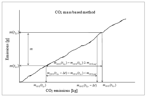
The duration (t2,i – t1,i) of the ith averaging window is determined by:

Where:
mCO2 (tj,i) is the CO2 mass measured between the test start and time tj,i, kg;
mCO2,ref is the CO2 mass determined for the WHTC, kg;
t2,i shall be selected such as:Δ<≤

Where Δt is the data sampling period, equal to 1 second or less.
The CO2 masses are calculated in the windows by integrating the instantaneous emissions calculated according to the requirements introduced in paragraph A.1.3.5.
A.1.4.3.1. Selection of valid windows
A.1.4.3.1.1. Before the dates referred to in paragraph 13.2.5. of this Regulation for new type approvals and paragraph 13.3.4. for new registrations, paragraphs A.1.4.3.1.1.1. to A.1.4.3.1.1.4. shall apply.
A.1.4.3.1.1.1. The valid windows shall be the windows whose duration does not exceed the maximum duration calculated from:

Where:
Dmax the maximum window duration, s;
Pmax is the maximum engine power, kW.
A.1.4.3.1.1.2. If the percentage of valid windows is less than 50 per cent, the data evaluation shall be repeated using longer window durations. This is achieved by decreasing the value of 0.2 in the formula given in paragraph A.1.4.3.1. by steps of 0.01 until the percentage of valid windows is equal to or greater than 50 per cent.
A.1.4.3.1.1.3.In any case, the lowered value in above formula shall not be lower than 0.15.
A.1.4.3.1.1.4.The test shall be void if the percentage of valid windows is less than 50 % at a maximum window duration calculated in accordance with paragraphs A.1.4.3.1.1.1., A.1.4.3.1.1.2. and A.1.4.3.1.1.3.
A.1.4.3.1.2. From the dates referred to in paragraph 13.2.5. of this Regulation for new type approvals and paragraph 13.3.4. for new registrations, paragraphs A.1.4.3.1.2.1. and A.1.4.3.1.2.2. shall apply.
A.1.4.3.1.2.1. The valid windows shall be the windows whose duration does not exceed the maximum duration calculated from:

where:
Dmax is the maximum window duration, s;
Pmax is the maximum engine power, kW.
A.1.4.3.1.2.2. The test shall be void if the percentage of valid windows is less than 50 per cent.
A.1.4.3.2. Calculation of the conformity factors
The conformity factors shall be calculated for each individual window and each individual pollutant in the following way:

Where
 (in service ratio) and
 (certification ratio)
Where:
m is the mass emission of the gaseous pollutant, mg/window, or the PM number, #/window;
mCO2 (t2,i) – mCO2 (t1,i) is the CO2 mass during the ith averaging window, kg;
mCO2,ref is the engine CO2 mass determined for the WHTC, kg;
mL is the mass emission of the gaseous pollutant or the PM number corresponding to the applicable limit on the WHTC, mg or # respectively.
A.1.4.4. Calculation of the final conformity factor for the test
A.1.4.4.1. The final conformity factor for the test (CFfinal) for each pollutant shall be calculated as follows:
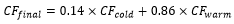
where:
CFcold is the conformity factor of the period of cold operation of the test, which shall be equal to the highest conformity factor of the moving averaging windows starting below 343 K (70 °C) coolant temperature, determined for that pollutant in accordance with the calculation procedures specified in paragraphs A.1.4.1. and either A.1.4.2. or, as applicable, A.1.4.3.;
CFwarm is the conformity factor of the period of warm operation of the test, which shall be equal to the 90th cumulative percentile of the conformity factors determined for that pollutant in accordance with the calculation procedures specified in paragraphs A.1.4.1. and either A.1.4.2. or, as applicable, A.1.4.3., when the data evaluation is started after the coolant temperature has reached 343 K (70 °C) for the first time.
Annex 8 ‑ Appendix 2 Portable measurement equipment
A.2.1. General
The gaseous emissions shall be measured according to the procedure set out in Appendix 1 to this annex. The present appendix describes the characteristics of the portable measurement equipment that shall be used to perform such tests.
A.2.2. Measuring equipment
A.2.2.1. Gas analysers general specifications
The PEMS gas analysers specification shall meet the requirements set out in paragraph 9.3.1 of Annex 4. The rise time of the analyser installed in the PEMS measurement system shall not exceed 3.5 seconds.
A.2.2.2. Gas analysers technology
The gases shall be analysed using the technologies specified in paragraph 9.3.2.of Annex 4.
The oxides of nitrogen analyser may also be of the Non-Dispersive Ultra Violet (NDUV) type.
A.2.2.3. Sampling of gaseous emissions
The sampling probes shall meet the requirements defined in paragraphs A.2.1.2. and A.2.1.3. of Appendix 2 to Annex 4 to this Regulation. The sampling line shall be heated to 190 °C (+/-10 °C).
A.2.2.4. Other instruments
The measuring instruments shall satisfy the requirements given in Table 7 in Annex 4 and paragraph 9.3.1. to Annex 4.
A.2.2.5. PM number analysers
A.2.2.5.1. General
A.2.2.5.1.1. The PM number analyser shall consist of a pre-conditioning unit and a particle detector (see Figure 1). The particle detector may also pre-condition the aerosol. The analyser’s sensitivity to shocks, vibrations, aging, variations in temperature and air pressure, electromagnetic interferences and other things that could affect the operation of the vehicle or the analyser shall be kept to a minimum as far as possible and shall be clearly stated in the supporting documentation produced by the instrument manufacturer. The PM number analyser shall fulfil the requirements of this Regulation and the specifications of the instrument manufacturer.
Figure 1
Example of a PM number analyser setup

Notes: dotted lines depict optional parts; EFM means Exhaust mass Flow Meter; d means inner diameter ; PND means PM Number Diluter
A.2.2.5.1.2. The PM number analyser shall be connected to the sampling point via a sampling probe which extracts a sample from the centreline of the tailpipe tube. If particles are not diluted at the tailpipe, the sampling line shall be heated to a minimum temperature of 373 K (100 °C) until the point of first dilution of the PM number analyser or the particle detector of the analyser. The residence time of the sample in the particle sampling line shall be less than 3 seconds to the point of first dilution or to the particle detector.
A.2.2.5.1.3. All parts in contact with the sampled exhaust gas shall be always kept at a temperature that avoids condensation of any compound in the device. That may be achieved e.g. by heating to a higher temperature and diluting the sample or oxidising the (semi)volatile species.
A.2.2.5.1.4. The PM number analyser shall include a heated section at wall temperature ≥ 573K (300 °C). The pre-conditioning unit shall control the heated stages to constant nominal operating temperatures, within a tolerance of ± 10 K and provide an indication of whether or not heated parts are at their correct operating temperatures. Lower temperatures are acceptable as long as the volatile particle removal efficiency meets the specifications set out in paragraph A.2.2.5.4.
A.2.2.5.1.5. Pressure, temperature and other sensors shall monitor the operation of the instrument during its operation and shall trigger a warning or message in case of malfunction.
A.2.2.5.1.6. The delay time inside the PM number analyser shall be < 5 s. Delay time means the time difference between a change of concentration at the reference point and a system response of 10 per cent of the final reading.
A.2.2.5.1.7. The PM number analyser (and/or particle detector) shall have a rise time of < 3.5 s.
A.2.2.5.1.8. Particle concentration measurements shall be reported normalised to 273 K (0 °C) and 101.3 kPa. If considered necessary using best engineering judgement, the pressure and/or temperature at the inlet of the detector shall be measured and reported for the purposes of normalising the particle concentration.
A.2.2.5.1.9. PM number analysers that comply with the calibration requirements of UN Regulation No. 83 or UN Regulation No. 154 shall be deemed to comply with the calibration requirements of this annex.
A.2.2.5.2. Efficiency requirements
A.2.2.5.2.1. The complete PM number analyser system and the sampling line, shall meet the efficiency requirements of Table 1:
Table 1
PM number analyser system (and sampling line) efficiency requirements
dp [nm] | sub-23 | 23 | 30 | 50 | 70 | 100 | 200 |
E(dp) | - (*) | 0.2-0.6 | 0.3-1.2 | 0.6-1.3 | 0.7-1.3 | 0.7-1.3 | 0.5-2.0 |
(*) Will be defined at a later stage
A.2.2.5.2.2. Efficiency E(dp) is the ratio in the readings of the PM number analyser system to a reference Condensation Particle Counter (CPC)’s (d50 = 10 nm or lower, checked for linearity and calibrated with an electrometer) or an Electrometer’s number concentration measuring in parallel monodisperse aerosol of mobility diameter dp and normalised at the same temperature and pressure conditions. The material shall be thermally stable and soot-like (e.g. spark discharged graphite or diffusion flame soot with thermal pre-treatment). If the efficiency curve is measured with a different aerosol (e.g. NaCl), the correlation to the soot-like curve shall be provided in the form of a chart which compares the efficiencies obtained using both test aerosols. The differences in the counting efficiencies shall be taken into account by adjusting the measured efficiencies based on that comparison chart to give soot-like aerosol efficiencies. Any correction for multiple charged particles shall be applied and documented, but it shall not exceed 10 per cent. The final efficiencies (e.g. adjusted for the different material and multiple charged particles) shall cover the PM number analyser and sampling line. The PM number analyser may alternatively be calibrated in parts (i.e. the pre-conditioning unit separately from the particle detector) provided that the PM number analyser and the sampling line together meet the requirements of Table 1. The signal measured from the detector shall be > 2 times the limit of detection (here defined as the zero level plus 3 standard deviations).
A.2.2.5.3. Linearity requirements
A.2.2.5.3.1. The linearity requirements shall be verified whenever damage is observed, as required by internal audit procedures or by the instrument manufacturer, at least once within the 12-month period leading up to a test.
A.2.2.5.3.2. The PM number analyser, and the sampling line, shall meet the linearity requirements set out in Table 2.
Table 2
Linearity requirements of PM number analyser (and the sampling line)
Measurement parameter/instrument | min (a1 - 1)+ a0 | Slope a1 | Standard error SEE | Coefficient of determination r2 |
PM number analyser | ≤ 5 per cent max | 0.85-1.15 | ≤ 10 per cent max | ≥ 0.950 |
A.2.2.5.3.3. The PM number analyser system and the sampling line, shall meet the linearity requirements of Table 2 using monodisperse or polydisperse soot-like particles. The particle size (mobility diameter or count median diameter) shall be larger than 45 nm. The reference instrument shall be an Electrometer or a Condensation Particle Counter (CPC) with d50 = 10 nm or lower, verified for linearity. Alternatively, the reference instrument may be a particle number system that complies with the requirements of paragraph 10. of Annex 4.
A.2.2.5.3.4. In addition, the differences between the PM number analyser and the reference instrument at each of the points that are checked (except the zero point) shall be within 15 per cent of their mean value. At least 5 points equally distributed (plus the zero point) shall be checked. The maximum checked concentration shall be the maximum allowed concentration of the PM number analyser. If the PM number analyser is calibrated in parts, the linearity may be checked only for the detector, but the efficiencies of the other parts and the sampling line shall be taken into account in the slope calculation.
A.2.2.5.4. Volatile removal efficiency
A.2.2.5.4.1. The PM number analyser system shall achieve > 99 per cent removal of ≥ 30 nm tetracontane (CH3(CH2)38CH3) particles with an inlet concentration of ≥ 10,000 particles per cubic centimetre at the minimum dilution.
A.2.2.5.4.2. Additionally, the PM number analyser system shall also achieve a > 99 per cent removal efficiency of polydisperse alcane (decane or higher) or emery oil with count median diameter > 50 nm and an inlet concentration of ≥ 5 × 10⁶ particles per cubic centimetre at the minimum dilution (equivalent mass > 1 mg/m3).
A.2.2.5.4.3. The volatile removal efficiency with tetracontane and/or polydisperse alcane or oil need to be proven only once for the PEMS family. A PEMS family is considered to be a group of instruments with the same analysers, sample and thermal conditioning and software compensation algorithms. The instrument manufacturer shall provide the maintenance or replacement interval that ensures that the removal efficiency does not drop below the technical requirements. If such information is not provided by the instrument manufacturer, the volatile removal efficiency shall be checked yearly for each instrument.
A.2.3. Auxiliary equipment
A.2.3.1. Exhaust Gas Flow Meter (EFM) tailpipe connection
The installation of the EFM shall not increase the backpressure by more than the value recommended by the engine manufacturer, nor increase the length of the tailpipe by more than 2 m. As for the all the components of the PEMS equipment, the installation of the EFM shall comply with the locally applicable road safety regulations and insurance requirements.
A.2.3.2. PEMS location and mounting hardware
The PEMS equipment shall be installed as specified in paragraph A.1.2.4. of Appendix 1 to this annex.
A.2.3.3. Electrical power
The PEMS equipment shall be powered using the method described in paragraph 4.6.6. of this annex.
Annex 8 ‑ Appendix 3 Calibration of portable measurement equipment
A.3.1. Equipment calibration and verification
A.3.1.1. Calibration gases
The PEMS gas analysers shall be calibrated using gases meeting the requirements as set out in paragraph 9.3.3. of Annex 4.
A.3.1.2. Leakage test
The PEMS leakage tests shall be conducted following the requirements defined in paragraph 9.3.4. of Annex 4.
A.3.1.3. Response time check of the analytical system
The response time check of the PEMS analytical system shall be conducted in accordance with the requirements set out in paragraph 9.3.5. of Annex 4.
A.3.1.4. PM number analyser calibration and verification
A.3.1.4.1. The PEMS leakage test shall be conducted either in accordance with the requirements set out in paragraph 9.3.4. of Annex 4 or in accordance with the instrument manufacturer’s instructions.
A.3.1.4.2. The response time check of the PM number analyser shall be conducted in accordance with the requirements set out in paragraph 9.3.5. of Annex 4 using particles if gases cannot be used.
A.3.1.4.3. The transformation time of the PM number analyser system and its sampling line, shall be determined in accordance with paragraph A.8.1.3.7. of Appendix 8 to Annex 4. "Transformation time" means the time difference between a change of concentration at the reference point and a system response of 50 per cent of the final reading.
Annex 8 ‑ Appendix 4 Method to check the conformity of the ECU torque-signal
A.4.1. Introduction
This appendix describes in a non-detailed manner the method used to check the conformity of the ECU torque-signal during ISC-PEMS testing.
The detailed applicable procedure is left to the engine manufacturer, subject to approval of the Type Approval Authority.
A.4.2. The "Maximum torque" method
A.4.2.1. The "Maximum torque" method consists of demonstrating that a point on the reference maximum torque curve as a function of the engine speed has been reached during vehicle testing.
A.4.2.1.1. If a market fuel declared in paragraph 3.2.2.2.1. of Part 1 of Annex 1 to this Regulation is used and a power correction factor in accordance with paragraph 3.2.2.2.2. of Part 1 of Annex 1 to this Regulation was documented for the dedicated market fuel used for the test, the ECU torque signal has to be multiplied by the inverted correction factor prior to the verification with the reference maximum torque curve performed with this specific market fuel.
A.4.2.2. If a point on the reference maximum torque curve as a function of the engine speed has not been reached during the ISC PEMS emissions testing, the manufacturer is entitled to modify the load of the vehicle and/or the testing route as necessary in order to perform that demonstration after the ISC PEMS emissions test has been completed.
Annex 9A On-board diagnostic systems (OBD)
1. Introduction
1.1. This annex sets out the functional aspects of on-board diagnostic (OBD) systems for the control of emissions from engine systems which are covered by this Regulation.
2. General requirements
2.1. The general requirements, including the specific requirements for electronic system security, shall be those set out in paragraph 4. of Annex 9B and those described in paragraph 2. of this annex.
2.2. Requirements regarding operating sequences and driving cycles for hybrid vehicles and vehicles with stop-start systems.
2.2.1.1. For vehicles that employ engine shut-off strategies that are commanded by the engine control system (for example hybrid bus with engine shut-off at idle) and that are followed by an engine cranking, the (engine shut-off – engine cranking) sequence shall be considered as part of the existing operating sequence.
2.2.1.2. The manufacturer shall provide the description of such strategies in the documentation considered in paragraphs 3.1.3. (a) and 3.1.3. (b) of this Regulation.
2.2.1.3. In the case of a hybrid vehicle, the operating sequence shall start at the time of the engine start or at the time when the vehicle starts moving, whichever occurs first.
2.2.2. Driving cycle
2.2.2.1. For vehicles that employ engine shut-off strategies that are commanded by the engine control system (for example hybrid bus with engine shut-off at idle) and that are followed by an engine cranking, the (engine shut-off – engine cranking) sequence shall be considered as part of the existing driving cycle.
2.2.2.2. The manufacturer shall provide the description of such strategies in the documentation considered in paragraphs 3.1.3. (a) and 3.1.3. (b) of this Regulation.
2.2.2.3. In the case of a hybrid vehicle, the driving cycle shall start at the time of the engine start or at the time when the vehicle starts moving, whichever occurs first.
2.3. Additional provisions concerning monitoring requirements.
2.3.1. Malfunctioning injectors
As an alternative to the monitor specified in line (d) of the table in item 7 of Appendix 3 to Annex 9B to this Regulation, the manufacturer may opt for compliance with the provisions specified in paragraphs 2.3.1.1. to 2.3.1.2.1. of this annex.
2.3.1.1. The manufacturer shall submit to the Type Approval Authority an analysis of the long-term effects on the emission control system of malfunctioning fuel injectors (for example clogged or soiled injectors) even if the OBD Threshold Limits (OTLs) are not exceeded as a consequence of these malfunctions.
2.3.1.2. After the period set out in paragraph 4.10.7. of this Regulation the manufacturer shall submit to the Type Approval Authority a plan of the monitoring techniques he intends to use in addition to those required by Appendix 3 to Annex 9B in order to diagnose the effects considered in paragraph 2.3.1.1.
2.3.1.2.1. After approval of this plan by the authority, the manufacturer shall implement those techniques in the OBD system in order to get a type approval.
2.3.2. Monitoring requirements concerning particulate after treatment devices
2.3.2.1. The performance of the particulate after treatment device including the filtration and continuous regeneration processes shall be monitored against the OBD threshold limit specified in Table 1.
2.3.2.2. In the case of a wall flow diesel particulate filter (DPF), until the date specified in paragraph 13.2.3. of this Regulation for new type approvals and paragraph 13.3.3. for new registrations, the manufacturer may choose to apply the performance monitoring requirements set out in Appendix 8 to Annex 9B instead of the requirements of paragraph 2.3.2.1., if he can demonstrate with technical documentation that in case of deterioration there is a positive correlation between the loss of filtration efficiency and the loss of pressure drop ("delta pressure") across the DPF under the operating conditions of the engine specified in the test described in Appendix 8 to Annex 9B.
2.4. Alternative approval
2.4.1. If requested by the manufacturer, for vehicles of categories M2 and N1, for vehicles of categories M1 and N2 with a technically permissible maximum laden mass not exceeding 7.5 tonnes, and for vehicles of category M3 Class I, Class II and Classes A and B[30] with a permissible mass not exceeding 7.5 tonnes, compliance with the requirements of Annex 11 to the 07 series of amendments to UN Regulation No. 83 or compliance with the requirements of Annex C5 of UN Regulation No. 154 shall be considered equivalent to the compliance with this annex, according to the following equivalences.
2.4.1.1. The OBD standard "Interim OBD threshold limits" in Table A11/3 of Annex 11 to the 07 series of amendments to Regulation No. 83 shall be considered as equivalent to the character A of the Table 1 of Annex 3 to this Regulation.
2.4.1.2. The OBD standard "Preliminary OBD threshold limits" in Table A11/2 of Annex 11 to the 07 series of amendments to Regulation No. 83 shall be considered as equivalent to the character B of the Table 1 of Annex 3 to this Regulation.
2.4.1.3. The OBD standard "Final OBD threshold limits" in Table A11/1 of Annex 11 to the 07 series of amendments to UN Regulation No. 83 shall be considered as equivalent to the characters C or D of the Table 1 of Annex 3 to this Regulation.
2.4.1.4. The OBD standard "Final OBD threshold limits" in Table 4A of UN Regulation No. 154 shall be considered as equivalent to the character E of the Table 1 of Annex 3 to this Regulation.
2.4.1.5. Special requirements for alternative approvals
2.4.1.5.1. If such alternative approval is used, the information related to OBD systems in paragraph 3.2.12.2.7. of Part 2 of Annex 1 is replaced by the information of paragraph 3.2.12.2.7. of Annex 1 to the 07 series of amendments to UN Regulation No. 83 or by the information of paragraph 3.2.12.2.7. of Annex A1 to Regulation No. 154.
2.4.1.5.2. The equivalences set out in paragraph 2.4.1. shall apply in the following manner:
2.4.1.5.2.1. The OTL's and dates referred to in Table 1 of Annex 3 to this Regulation and relevant to the assigned character for which the type-approval is sought shall apply;
2.4.1.5.2.2. The requirements on NOx control measures described in paragraphs 2.1.2.2.1. to 2.1.2.2.4. of Annex 11 shall apply.
2.4.2. As an alternative to the requirements set out in paragraph 4. of Annex 9B and those described in this annex, engine manufacturers whose world-wide annual production of engines within an engine type subject to this Regulation is less than 500 engines per year, may obtain type approval on the basis of the requirements of this Regulation when the emission control components of the engine-system are at least monitored for circuit continuity, and for rationality and plausibility of sensor outputs, and when the after-treatment system is at least monitored for total functional failure. Engine manufacturers whose world-wide annual production of engines within an engine type subject to this Regulation is less than 50 engines per year, may obtain type approval on the basis of the requirements of this Regulation when the emission control components of the engine system are at least monitored for circuit continuity, and for rationality and plausibility of sensor outputs ("component monitoring").
A manufacturer shall not be permitted to use the alternative provisions specified in this paragraph for more than 500 engines per year.
2.4.3. The Type Approval Authority shall inform the other Contracting Parties of the circumstances of each type approval granted under paragraph 2.4.1. and paragraph 2.4.2.
2.5. Conformity of production
The OBD system is subject to the requirements for conformity of production specified in paragraph 8.4. of this Regulation.
If the Type Approval Authority decides that verification of the conformity of production of the OBD system is required, the verification shall be conducted in accordance with the requirements specified in paragraph 8.4. of this Regulation.
3. Performance requirements
3.1. The performance requirements shall be those set out in paragraph 5. of Annex 9B.
3.2. OBD threshold limits
3.2.1. The OBD threshold limits (hereinafter OTLs) applicable to the OBD system are those specified in the rows "general requirements" of Table 1 for compression ignition engines and of Table 2 for gas-fuelled engines and positive ignition engines.
3.2.2. Until the end of the phase-in period set out in paragraph 4.10.7. of this Regulation, the OBD threshold limits specified in rows "phase-in period" of Table 1 for compression ignition engines and of Table 2 for gas fuelled engines and positive ignition engines.
Table 1
OTLs (Compression ignition engines)
| Limit in mg/kWh |
| NOx | PM Mass |
Phase-in period | 1,500 | 25 |
General requirements | 1,200 | 25 |
Table 2
OTLs (positive ignition engines)
| Limit in mg/kWh |
| NOx | CO1 |
Phase-in period | 1 500 | 7 500 |
General requirements | 1 200 | 7 500 |
1 The transitional provisions related to introduction of the CO OTLs are specified in paragraphs 13.2.2. and 13.3.2. of this Regulation.
4. Demonstration requirements
4.1. The demonstration requirements and test procedures shall be those set out in paragraphs 6. and 7. of Annex 9B.
5. Documentation requirements
5.1. The documentation requirements shall be those set out in paragraph 8. of Annex 9B.
6. In-use performance requirements
The requirements of this paragraph shall apply to the OBD system monitors in accordance with the provisions of Annex 9C.
6.1. Technical requirements
6.1.1. The technical requirements for assessing the in-use performance of OBD systems including requirements concerning communication protocols, numerators, denominators and their increment shall be those set out in Annex 9C.
6.1.2. In particular, the in-use performance ratio (IUPRm) of a specific monitor m of the OBD system shall be calculated by the following formula:
IUPRm = Numeratorm / Denominatorm
Where:
"Numeratorm" means the numerator of a specific monitor m and is a counter indicating the number of times a vehicle has been operated in such a way that all monitoring conditions necessary for that specific monitor to detect a malfunction have been encountered;
and
"Denominatorm" means the denominator of a specific monitor m and is a counter indicating the number of vehicle driving cycles that are of relevance to that specific monitor (or, "in which events occur that are of relevance to that specific monitor. ").
6.1.3. The in-use performance ratio (IUPRg) of a group g of monitors on board a vehicle is calculated by the following formula:
IUPRg = Numeratorg / Denominatorg
Where:
"Numeratorg" means the numerator of a group g of monitors and is the actual value (Numeratorm) of the specific monitor m that has the lowest in-use performance ratio as defined in paragraph 6.1.2. of all monitors within that group g of monitors on board a particular vehicle;
and
"Denominatorg" means the denominator of a group g of monitors and is the actual value (Denominatorm) of the specific monitor m that has the lowest in-use performance ratio as defined in paragraph 6.1.2. of all monitors within that group g of monitors on board a particular vehicle.
6.2. Minimum in-use performance ratio
6.2.1. The in-use performance ratio IUPRm of a monitor m of the OBD system as defined in paragraph 5. of Annex 9C, shall be greater than or equal to the minimum in-use-performance ratio IUPRm(min) applicable to the monitor m throughout the useful life of the engine as specified in paragraph 5.4. of this Regulation.
6.2.2. The value of minimum in-use-performance ratio IUPR(min) is 0.1 for all monitors.
6.2.3. The requirement of paragraph 6.2.1. is deemed to be fulfilled if for all groups of monitors g the following conditions are met:
6.2.3.1. The average value  of the values IUPRg of all vehicles equipped with engines belonging to the OBD engine family under consideration is equal to or above IUPR(min), and
6.2.3.2. More than 50 per cent of all engines considered in paragraph 6.2.3.1. have an IUPRg equal to or above IUPR(min).
6.3. Documentation requirements
6.3.1. The documentation associated with each monitored component or system and required by paragraph 8. of Annex 9B shall include the following information concerning in-use performance data:
a) The criteria used for incrementing the numerator and the denominator;
b) Any criterion for disabling incrementation of the numerator or of the denominator.
6.3.1.1. Any criterion for disabling incrementation of the general denominator shall be added to the documentation referred to in paragraph 6.3.1.
6.4. Statement of OBD in-use Performance compliance
6.4.1. In the application for type approval, the manufacturer shall provide a statement of OBD in-use Performance compliance in accordance with the model set out in Appendix 2 to this annex. In addition to this statement, compliance with the requirements of paragraph 6.1. shall be verified through the additional assessment rules specified in paragraph 6.5.
6.4.2. This statement referred to in paragraph 6.4.1. shall be attached to the documentation related to the OBD engine-family required by paragraphs 5. and 6.3. of this annex.
6.4.3. The manufacturer shall maintain records which contain all test data, engineering and manufacturing analyses, and other information which provides the basis for the OBD in-use performance compliance statement. The manufacturer shall make such information available to the Type Approval Authority upon request.
6.4.4. During the phase-in period set out in paragraph 4.10.7. of this Regulation, the manufacturer shall be exempted from providing the statement required by paragraph 6.4.1.
6.5. Assessment of the in-use performance
6.5.1. The OBD in-use performance and compliance with paragraph 6.2.3. of this annex shall be demonstrated at least according to the procedure set out in Appendix 1 to this annex.
6.5.2. National authorities and their delegates may pursue further tests to verify compliance with paragraph 6.2.3. of this annex.
6.5.2.1. To demonstrate non-compliance with the requirements of paragraph 6.2.3. of this annex, based on the provision of paragraph 6.5.2. of this annex, the authorities must show for at least one of the requirements of paragraph 6.2.3. of this annex non-compliance with a statistical confidence level of 95 per cent, based on a sample of at least 30 vehicles.
6.5.2.2. The manufacturer shall have the opportunity to establish compliance with the requirements of paragraph 6.2.3. of this annex, for which non-compliance was demonstrated according to paragraph 6.5.2.1. of this annex, by using a test based on a sample of at least 30 vehicles, with a better statistical confidence than the test mentioned in paragraph 6.5.2.1.
6.5.2.3. For tests performed according to paragraphs 6.5.2.1. and 6.5.2.2. both authorities and manufacturers must disclose relevant details, such as those relating to the selection of the vehicles, to the other party.
6.5.3. If non-compliance with the requirements of paragraph 6.2.3. of this annex is established according to paragraphs 6.5.1. or 6.5.2. of this annex, remedial measures in accordance with paragraph 9.3. of this Regulation shall be taken.
Annex 9A ‑ Appendix 1 Assessment of the in-use performance of the on-board diagnostic system
A.1.1. General
A.1.1.1. This appendix sets out the procedure to be followed when demonstrating the OBD in-use performance with regard to the provisions set out in paragraph 6. of this annex.
A.1.2. Procedure for demonstrating OBD in-use performance
A.1.2.1. The OBD in-use performance of an engine family shall be demonstrated by the manufacturer to the Type Approval Authority that granted the type approval for the vehicles or engines concerned. The demonstration shall require consideration of the OBD in-use performance of all OBD engine families within the engine family under consideration (Figure 1).
Figure 1
Two OBD engine families within one engine family
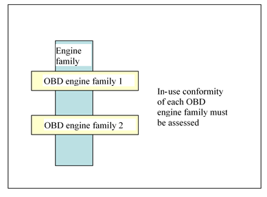
A.1.2.1.1. The demonstration of OBD in-use performance shall be organised and conducted by the manufacturer, in close cooperation with the Type Approval Authority.
A.1.2.1.2. The manufacturer may use in the demonstration of conformity relevant elements that were used to demonstrate the conformity of an OBD engine family within another engine family provided that this earlier demonstration took place no more than two years before the current demonstration (Figure 2).
A.1.2.1.2.1. A manufacturer may not, however, then use these elements in demonstrating conformity of a third or subsequent, engine family unless each of these demonstrations takes place within two years of the first use of the elements in a demonstration of conformity.
Figure 2
Previously demonstrated conformity of an OBD engine family
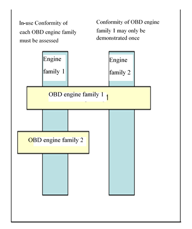
A.1.2.2. The demonstration of OBD in-use performance shall be performed at the same time and at the same frequency as the in-service conformity demonstration specified in Annex 8.
A.1.2.3. The manufacturer shall report the initial schedule and the sampling plan for conformity testing to the Type Approval Authority at the time of the initial type approval of a new engine family.
A.1.2.4. Vehicle types without a communication interface which permits the collection of the necessary in-use performance data as specified in Annex 9C, with missing data or with a non-standard data protocol shall be considered as non-compliant.
A.1.2.4.1. Individual vehicles with mechanical or electrical faults which prevent the collection of the necessary in-use performance data as specified in Annex 9C shall be excluded from the conformity testing survey and the vehicle type shall not be considered non-compliant unless insufficient vehicles that meet the sampling requirements can be found to permit the survey to be properly conducted.
A.1.2.5. Engine or vehicle types where the collection of in-use performance data influences the OBD monitoring performance shall be considered as non-compliant.
A.1.3. OBD in-use performance data
A.1.3.1. The OBD in-use performance data to be considered for assessing the conformity of an OBD engine family shall be those recorded by the OBD system according to paragraph 6. of Annex 9C, and made available according to paragraph 7. of that annex.
A.1.4. Engine or vehicle selection
A.1.4.1. Engine selection
A.1.4.1.1. In the case where an OBD engine family is used in several engine families (Figure 2), engines from each of these engine families shall be selected by the manufacturer for demonstrating the in-use performance of that OBD engine family.
A.1.4.1.2. Any engine of a particular OBD-engine family may be included in the same demonstration even if the monitoring systems with which they are equipped are of different generations or at different modification states.
A.1.4.2. Vehicle selection
A.1.4.2.1. Vehicle segments
A.1.4.2.1.1. For the purpose of classifying the vehicles subject to demonstration, 6 vehicle segments shall be considered:
(a) For vehicles of class N: long-haul vehicles, distribution vehicles, and others, such as construction vehicles.
(b) For vehicles of class M: coaches and inter-city buses, city buses, and others, such as M1 vehicles.
A.1.4.2.1.2. Where possible, vehicles shall be selected from each segment in a survey.
A.1.4.2.1.3. There shall be a minimum of 15 vehicles per segment.
A.1.4.2.1.4. In the case where an OBD engine-family is used in several engine families (Figure 2), the number of engines from each of these engine families within a vehicle segment shall be as representative as possible of their volume share, in terms of vehicles sold and in use, for that vehicle segment.
A.1.4.2.2. Vehicle qualification
A.1.4.2.2.1. The engines selected shall be fitted to vehicles registered and used in a country of the Contracting Parties.
A.1.4.2.2.2. Each vehicle selected shall have a maintenance record to show that the vehicle has been properly maintained and serviced in accordance with the manufacturer's recommendations.
A.1.4.2.2.3. The OBD system shall be checked for proper functioning. Any malfunction indications relevant to the OBD system itself that are stored in the OBD memory shall be recorded and the required repairs shall be carried out.
A.1.4.2.2.4. The engine and vehicle shall exhibit no indications of abuse such as overloading, misfueling, or other misuse, or other factors, such as tampering that could affect the OBD performance. OBD system fault codes and information on operating hours stored in the computer memory shall be amongst the evidence taken into account in determining whether the vehicle has been subject to abuse or is otherwise ineligible for inclusion in a survey.
A.1.4.2.2.5. All emission control system and OBD components on the vehicle shall be as stated in the applicable type approval documents.
A.1.5. In-use performance surveys
A.1.5.1. Collection of in-use performance data
A.1.5.1.1. In accordance with the provisions of paragraph A.1.6., the manufacturer shall retrieve the following information from the OBD system of each vehicle in the survey:
(a) The VIN (vehicle identification number);
(b) The numeratorg and denominatorg for each group of monitors recorded by the system in accordance with the requirements of paragraph 6. of Annex 9C;
(c) The general denominator;
(d) The value of the ignition cycle counter;
(e) The total engine running hours.
A.1.5.1.2. The results from the group of monitors under evaluation shall be disregarded if a minimum value of 25 for its denominator has not been reached.
A.1.5.2. Assessment of the in-use performance
A.1.5.2.1. The actual performance ratio per group of monitors of an individual engine (IUPRg) shall be calculated from the numeratorg and denominatorg retrieved from the OBD system of that vehicle.
A.1.5.2.2. The assessment of the in-use performance of the OBD engine family in accordance with the requirements of paragraph 6.5.1. of this annex shall be made for each group of monitors within the OBD-engine family considered in a vehicle segment.
A.1.5.2.3. For any segment of vehicles defined in paragraph A.1.4.2.1. of this Appendix, the OBD in-use performance is considered as being demonstrated for the purposes of paragraph 6.5.1. of this annex if, and only if, for any group g of monitors the following conditions are met:
(a) The average value  of the IUPRg values of the considered sample is greater than 88 per cent of IUPR(min); and
(b) More than 34 per cent of all engines in the considered sample have an IUPRg value of more or equal than IUPR(min).
A.1.6. Report to the Type Approval Authority
The manufacturer shall provide the Type Approval Authority with a report on the in-use performance of the OBD engine family that contains the following information:
A.1.6.1. The list of the engine families within the considered OBD engine family (Figure 1)
A.1.6.2. The following information concerning the vehicles considered in the demonstration:
(a) The total number of vehicles considered in the demonstration;
(b) The number and the type of vehicle segments;
(c) The VIN, and a short description (type-variant-version) of each vehicle.
A.1.6.3. In-use performance information for each vehicle:
(a) The numeratorg, denominatorg, and in-use performance ratio (IUPRg) for each group of monitors;
(b) The general denominator, the value of the ignition cycle counter, the total engine running hours.
A.1.6.4. The results of the in-use performance statistics for each group of monitors:
(a) The average value of the IUPRg values of the sample;
(b) The number and the percentage of engines in the sample that have an IUPRg equal to or above IUPRm(min).
Annex 9A ‑ Appendix 2 Model of an OBD in-use performance compliance statement
"(Name of manufacturer) attests that the engines within this OBD engine family have been so designed and manufactured as to comply with all requirements of paragraphs 6.1. and 6.2. of Annex 9A.
(Name of manufacturer) makes this statement in good faith, after having performed an appropriate engineering evaluation of the OBD in-use performance of the engines within the OBD engine family over the applicable range of operating and ambient conditions."
[date]
Annex 9B Technical requirements for on-board diagnostic systems (OBD)
1. Introduction
This annex sets out the technical requirements of on-board diagnostic (OBD) systems for the control of emissions from engine systems which are covered by this Regulation.
This annex is based on the world-wide harmonized OBD global technical regulation (gtr) No. 5.
2. Reserved[31]
3. Definitions
3.1. "Alert system" means a system on-board the vehicle which informs the driver of the vehicle or any other interested party that the OBD system has detected a malfunction.
3.2. "Calibration verification number" means the number that is calculated and reported by the engine system to validate the calibration/software integrity.
3.3. "Component monitoring" means the monitoring of input components for electrical circuit failures and rationality failures and monitoring of output components for electrical circuit failures and functionality failures. It refers to components that are electrically connected to the controller(s) of the engine system.
3.4. "Confirmed and active DTC" means a DTC that is stored during the time the OBD system concludes that a malfunction exists.
3.5. "Continuous-MI" means the malfunction indicator showing a steady indication from the time the key is moved to on (run) position and the engine is started (ignition on – engine on) or the vehicle starts moving, whichever occurs first, and extinguishing when the key is moved to off.
3.6. "Deficiency" means an OBD monitoring strategy or other OBD feature that does not meet all the detailed requirements of this annex.
3.7. "Electrical circuit failure" means a malfunction (e.g. open circuit or short circuit) that leads to the measured signal (i.e. voltages, currents, frequencies, etc.) being outside the range where the transfer functions of the sensor is designed to operate.
3.8. "Emission OBD family" means a manufacturer's grouping of engine systems having common methods of monitoring/diagnosing emission-related malfunctions.
3.9. "Emission threshold monitoring" means monitoring of a malfunction that leads to an excess of the OBD threshold limits (OTLs) and which consists of either or both of the following:
(a) Direct emissions measurement via a tailpipe emissions sensor(s) and a model to correlate the direct emissions to specific emissions of the applicable test-cycle;
(b) Indication of an emissions increase via correlation of computer input and output information to test-cycle specific emissions.
3.10. "Functionality failure" means a malfunction where an output component does not respond to a computer command in the expected way.
3.11. "Malfunction emission control strategy (MECS)" means a strategy within the engine system that is activated as a result of an emission-related malfunction.
3.12. "MI status" means the command status of the MI, being either continuous-MI, Short-MI, on-demand-MI, or off.
3.13. "Monitoring" (see "emission threshold monitoring", "performance monitoring", and "total functional failure monitoring")
3.14. "OBD test-cycle" means the cycle over which an engine system is operated on an engine test-bed to evaluate the response of an OBD system to the presence of a qualified deteriorated component.
3.15. "OBD-parent engine system" means an engine system that has been selected from an emission-OBD family for which most of its OBD elements of design are representative of that family.
3.16. "On-demand-MI" means the malfunction indicator showing a steady indication in response to a manual demand from the driving position when the key is in the on (run) position with the engine off (ignition on - engine off).
3.17. "Pending DTC" means a DTC that is stored by the OBD system because a monitor has detected a situation where a malfunction may be present during the current or last completed operating sequence.
3.18. "Potential DTC" means a DTC that is stored by the OBD system because a monitor has detected a situation where a malfunction may be present but requires further evaluation to be confirmed. A potential DTC is a pending DTC which is not a confirmed and active DTC.
3.19. "Previously active DTC" means a formerly confirmed and active DTC that remains stored after the OBD system has concluded that the malfunction that caused the DTC is no longer present.
3.20. "Rationality failure" means a malfunction where the signal from an individual sensor or component is at variance with that expected when assessed against signals available from other sensors or components within the control system. Rationality failures include malfunctions that lead to the measured signals (i.e. voltages, currents, frequencies, etc.) being inside the range where the transfer functions of the sensor is designed to operate.
3.21. "Readiness" means a status indicating whether a monitor or a group of monitors have run since the last erasing by an external request or command (for example through an OBD scan-tool).
3.22. "Short-MI" means the malfunction indicator showing a 15 seconds steady indication from the time the key is moved to on (run) position and the engine is started (ignition on - engine on) or the vehicle starts moving, and extinguishing either after these 15 seconds or when the key is moved to off, whichever occurs first."
3.23. "Software calibration identification" means a series of alphanumeric characters that identifies the emission-related calibration / software version(s) installed in the engine system.
3.24. "Total functional failure monitoring" means monitoring a malfunction which is leading to a complete loss of the desired function of a system.
3.25. "Warm-up cycle" means sufficient engine operation such that the coolant temperature has risen by at least 22 K (22 °C / 40 °F) from engine starting and reaches a minimum temperature of 333 K (60 °C / 140 °F).
3.26. Abbreviations
AES Auxiliary Emission Strategy
CV Crankcase Ventilation
DOC Diesel Oxidation Catalyst
DPF Diesel Particulate Filter or Particulate Trap including catalyzed DPFs and Continuously Regenerating Traps (CRT)
DTC Diagnostic trouble code
EGR Exhaust Gas Recirculation
HC Hydrocarbon
LNT Lean NOx Trap (or NOx absorber)
LPG Liquefied Petroleum Gas
MECS Malfunction Emission Control Strategy
NG Natural Gas
NOx Oxides of Nitrogen
OTL OBD Threshold Limit
PM Particulate Matter
SCR Selective Catalytic Reduction
SW Screen Wipers
TFF Total Functional Failure monitoring
VGT Variable Geometry Turbocharger
VVT Variable Valve Timing
4. General requirements
In the context of this annex, the OBD system shall have the capability of detecting malfunctions, of indicating their occurrence by means of a malfunction indicator, of identifying the likely area of the malfunctions by means of information stored in computer memory, and communicating that information off-board.
The OBD system shall be designed and constructed so as to enable it to identify types of malfunctions over the complete life of the vehicle/engine. In achieving this objective, the Type Approval Authority will recognize that engines which have been used in excess of their regulatory useful life may show some deterioration in OBD system performance and sensitivity such that the OBD thresholds may be exceeded before the OBD system signals a malfunction to the driver of the vehicle.
The above paragraph does not extend the engine manufacturer's compliance liability for an engine beyond its regulated useful life (i.e. the time or distance period during which emission standards or emission limits continue to apply).
4.1. Application for approval of an OBD system
4.1.1. Primary approval
The manufacturer of an engine system may apply for the approval of its OBD system in one of the three following manners:
(a) The manufacturer of an engine system applies for the approval of an individual OBD system by demonstrating that OBD system complies with all the provisions of this annex;
(b) The manufacturer of an engine system applies for the approval of an emission-OBD family by demonstrating that the OBD-parent engine system of the family complies with all the provisions of this annex.
The manufacturer of an engine system applies for the approval of an OBD system by demonstrating that OBD system meets the criteria for belonging to an emission-OBD family that has already been certified.
4.1.2. Extension / Modification of an existing certificate
4.1.2.1. Extension to include a new engine system into an emission-OBD family
At the request of the manufacturer and upon approval of the Type Approval Authority, a new engine system may be included as a member of a certified emission-OBD family if all the engine systems within the so-extended emission-OBD family still have common methods of monitoring / diagnosing emission-related malfunctions.
If all OBD elements of design of the OBD-parent engine system are representative of those of the new engine system, then the OBD-parent engine system shall remain unchanged and the manufacturer shall modify the documentation package according to paragraph 8. of this annex.
If the new engine system contains elements of design that are not represented by the OBD-parent engine system but itself would represent the whole family, then the new engine system shall become the new OBD-parent engine
system. In this case the new OBD elements of design shall be demonstrated to comply with the provisions of this annex, and the documentation package shall be modified according to paragraph 8. of this annex.
4.1.2.2. Extension to address a design change that affects the OBD system
At the request of the manufacturer and upon approval of the Type Approval Authority, an extension of an existing certificate may be granted in the case of a design change of the OBD system if the manufacturer demonstrates that the design changes comply with the provisions of this annex.
The documentation package shall be modified according to paragraph 8. of this annex.
If the existing certificate applies to an emission-OBD family, the manufacturer shall justify to the Type Approval Authority that the methods of monitoring/diagnosing emission-related malfunctions are still common within the family and that the OBD-parent engine system remains representative of the family.
4.1.2.3. Certificate modification to address a malfunction reclassification
This paragraph applies when, following a request by the authority that granted the approval, or at its own initiative, the manufacturer applies for a modification of an existing certificate in order to reclassify one or several malfunctions.
The compliance of the new classification shall then be demonstrated according to the provisions of this annex and the documentation package shall be modified according to paragraph 8. of this annex.
4.2. Monitoring requirements
All emission-related components and systems included in an engine system shall be monitored by the OBD system in accordance with the requirements set in Appendix 3 and, in the case of dual-fuel engines or vehicles in section 7. of Annex 15. However, the OBD system is not required to use a unique monitor to detect each malfunction referred to in Appendix 3 and, in the case of dual-fuel engines or vehicles in section 7. of Annex 15.
The OBD system shall also monitor its own components.
The items of Appendix 3 to this annex list the systems or components required to be monitored by the OBD system and describes the types of monitoring expected for each of these components or systems (i.e. emission threshold monitoring, performance monitoring, total functional failure monitoring, or component monitoring).
The manufacturer can decide to monitor additional systems and components.
4.2.1. Selection of the monitoring technique
Approval authorities may approve a manufacturer's use of another type of monitoring technique than the one mentioned in Appendix 3 or, in the case of dual-fuel engines or vehicles in section 7. of Annex 15. The chosen type of monitoring shall be shown by the manufacturer, to be robust, timely and efficient (i.e. through technical considerations, test results, previous agreements, etc.).
In case a system and/or component is not covered by Appendix 3 or, in the case of dual-fuel engines or vehicles in section 7. of Annex 15, the manufacturer shall submit for approval to the Type Approval Authority an approach to monitoring. The Type Approval Authority will approve the chosen type of monitoring and monitoring technique (i.e. emission threshold monitoring, performance monitoring, total functional failure monitoring, or component monitoring) if it has been shown by the manufacturer by reference to those detailed in Appendix 3 or, in the case of dual- fuel engines or vehicles in section 7. of Annex 15, to be robust, timely and efficient (i.e. through either technical considerations, test results, previous agreements, etc.).
4.2.1.1. Correlation to actual emissions
In the case of emission threshold monitoring, a correlation to test-cycle specific emissions shall be required. This correlation would typically be demonstrated on a test engine in a laboratory setting.
In all other monitoring cases (i.e. performance monitoring, total functional failure monitoring, or component monitoring), no correlation to actual emissions is necessary. However, the Type Approval Authority may request test data to verify the classification of the malfunction effects as described in paragraph 6.2. of this annex.
Examples:
An electrical malfunction may not require a correlation because this is a yes/no malfunction. A DPF malfunction monitored via delta pressure may not require a correlation because it anticipates a malfunction.
If the manufacturer demonstrates, according to the demonstration requirements of this annex, that emissions would not exceed the OBD threshold limits upon total failure or removal of a component or system, a performance monitoring of this component or system shall be accepted.
When a tailpipe emission sensor is used for monitoring the emissions of a specific pollutant all other monitors may be exempted from further correlation to the actual emissions of that pollutant. Nevertheless, such exemption shall not preclude the need to include these monitors, using other monitoring techniques, as part of the OBD system as the monitors are still needed for the purpose of malfunction isolation.
A malfunction shall always be classified according to paragraph 4.5. based on its impact on emissions, regardless of the type of monitoring used to detect the malfunction.
4.2.2. Component monitoring (input/output components/systems)
In the case of input components that belong to the engine system, the OBD system shall at a minimum detect electrical circuit failures and, where feasible, rationality failures.
The rationality failure diagnostics shall then verify that a sensor output is neither inappropriately high nor inappropriately low (i.e. there shall be "two-sided" diagnostics).
To the extent feasible, and with the agreement of the Type Approval Authority, the OBD system shall detect separately, rationality failures (e.g. inappropriately high and inappropriately low), and electrical circuit failures (e.g. out-of-range high and out-of-range low). Additionally, unique DTCs for each distinct malfunction (e.g. out-of-range low, out-of-range high and rationality failure) shall be stored.
In the case of output components that belong to the engine system, the OBD system shall at a minimum detect electrical circuit failures, and, where feasible, if the proper functional response to computer commands does not occur.
To the extent feasible, and with the agreement of the Type Approval Authority, the OBD system shall detect separately functionality failures, electrical circuit failures (e.g. out-of-range high and out-of-range low) and store unique DTCs for each distinct malfunction (e.g. out-of-range low, out-of-range high, functionality failure).
The OBD system shall also perform rationality monitoring on the information coming from or provided to components that do not belong to the engine system when this information compromises the emission control system and/or the engine system for proper performance.
4.2.2.1. Exception to component monitoring
Monitoring of electrical circuit failures, and to the extent feasible, functionality, and rationality failures of the engine system shall not be required if all the following conditions are met:
(a) The failure results in an emission increase of any pollutant of less than 50 per cent of the regulated emission limit; and
(b) The failure does not cause any emission to exceed the regulated emission limit[33]; and
(c) The failure does not affect a component or system enabling the proper performance of the OBD system; and
(d) The failure does not substantially delay or affect the ability of the emission control system to operate as originally designed (for example a breakdown of the reagent heating system under cold conditions cannot be considered as an exception).
Determination of the emissions impact shall be performed on a stabilized engine system in an engine dynamometer test cell, according to the demonstration procedures of this annex.
When such a demonstration would not be conclusive regarding criterion (d), the manufacturer shall submit to the Type Approval Authority appropriate design elements such as good engineering practice, technical considerations, simulations, test results, etc.
4.2.3. Monitoring frequency
Monitors shall run continuously, at any time where the monitoring conditions are fulfilled, or once per operating sequence (e.g. for monitors that lead to an increase of emission when it runs).
At the request of the manufacturer, the Type Approval Authority may approve monitors that do not run continuously. In that case the manufacturer shall clearly inform the Type Approval Authority and describe the conditions under which the monitor runs and justify the proposal by appropriate design elements (such as good engineering practice).
The monitors shall run during the applicable OBD test-cycle as specified in paragraph 7.2.2.
A monitor shall be regarded as running continuously, if it runs at a rate not less than twice per second and concludes the presence or the absence of the failure relevant to that monitor within 15 seconds. If a computer input or output component is sampled less frequently than twice per second for engine control purpose, a monitor shall also be regarded as running continuously, if the system concludes the presence or the absence of the failure relevant to that monitor each time sampling occurs.
For components or systems monitored continuously, it is not required to activate an output component/system for the sole purpose of monitoring that output component/system.
4.3. Requirements for recording OBD information
When a malfunction has been detected but is not yet confirmed, the possible malfunction shall be considered as a "Potential DTC" and accordingly a "Pending DTC" status shall be recorded. A "Potential DTC" shall not lead to an activation of the alert system according to paragraph 4.6.
Within the first operating sequence, a malfunction may be directly considered "confirmed and active" without having been considered a "potential DTC". It shall be given the "Pending DTC" and a "confirmed and active DTC" status.
In case a malfunction with the previously active status occurs again, that malfunction may at the choice of manufacturer be directly given the "Pending DTC" and "confirmed and active DTC" status without having been given the "potential DTC" status. If that malfunction is given the potential status, it shall also keep the previously active status during the time it is not yet confirmed and active.
The monitoring system shall conclude whether a malfunction is present before the end of the next operating sequence following its first detection. At this time, a "confirmed and active" DTC shall be stored and the alert system be activated according to paragraph 4.6.
In case of a recoverable MECS (i.e. the operation automatically returns to normal and the MECS is de-activated at the next engine ON), a "confirmed and active" DTC need not be stored unless the MECS is again activated before the end of the next operating sequence. In case of a non-recoverable MECS, a "confirmed and active" DTC shall be stored as soon as the MECS is activated.
In some specific cases where monitors need more than two operating sequences to accurately detect and confirm a malfunction (e.g. monitors using statistical models or with respect to fluid consumption on the vehicle), the Type Approval Authority may permit the use of more than two operating sequences for monitoring provided the manufacturer justifies the need for the longer period (e.g. by technical rationale, experimental results, in house experience, etc.).
When a confirmed and active malfunction is no longer detected by the system during a complete operating sequence, it shall be given the previously active status by the start of the next operating sequence and keep that status until the OBD information associated with this malfunction is erased by a scan tool or erased from the computer memory according to paragraph 4.4.
Note: The requirements prescribed in this paragraph are illustrated in Appendix 2 to this annex.
4.4. Requirements for erasing OBD information
DTC and the applicable information (inclusive the associated freeze frame) shall not be erased by the OBD system itself from the computer memory until that DTC has been in the previously active status for at least 40 warm-up cycles or 200 engine operating hours, whichever occurs first. The OBD system shall erase all the DTCs and the applicable information (inclusive the associated freeze frame) upon request of a scan tool or a maintenance tool.
4.5. Requirements for malfunction classification
Malfunction classification specifies the class to which a malfunction is assigned, when such a malfunction is detected according to the requirements of paragraph 4.2. of this annex.
A malfunction shall be assigned to one class for the actual life of the vehicle unless the authority that granted the certificate or the manufacturer determines that reclassification of that malfunction is necessary.
If a malfunction would result in a different classification for different regulated pollutant emissions or for its impact on other monitoring capability, the malfunction shall be assigned to the class that takes precedence in the discriminatory display strategy (for example Class A takes precedence over Class B1).
If an MECS is activated as a result of the detection of a malfunction, this malfunction shall be classified based on either the emission impact of the activated MECS or its impact on other monitoring capability. The malfunction shall then be assigned to the class that takes precedence in the discriminatory display strategy.
4.5.1. Class A malfunction
A malfunction shall be identified as Class A when the relevant OBD threshold limits (OTLs) are assumed to be exceeded.
The emissions may still remain below the OTLs when this class of malfunction occurs.
4.5.2. Class B1 malfunction
A malfunction shall be identified as Class B1 where circumstances exist that have the potential to lead to emissions being above the OTLs but for which the exact influence on emission cannot be estimated and thus the actual emissions according to circumstances may be above or below the OTLs.
Examples of Class B1 malfunctions may include malfunctions detected by monitors that infer emission levels based on readings of sensors or restricted monitoring capability.
Class B1 malfunctions shall include malfunctions that restrict the ability of the OBD system to carry out monitoring of Class A or B1 malfunctions.
4.5.3. Class B2 malfunction
A malfunction shall be identified as Class B2 when circumstances exist that are assumed to influence emissions but not to a level that exceeds the OTL.
Malfunctions that restrict the ability of the OBD system to carry out monitoring of Class B2 malfunctions of shall be classified into Class B1 or B2.
4.5.4. Class C malfunction
A malfunction shall be identified as Class C when circumstances exist that, if monitored, are assumed to influence emissions but to a level that would not exceed the regulated emission limits.
Malfunctions that restrict the ability of the OBD system to carry out monitoring of Class C malfunctions shall be classified into Class B1 or B2.
4.6. Alert system
The failure of a component of the alert system shall not cause the OBD system to stop functioning.
4.6.1. MI specification
The malfunction indicator shall be a visual signal that is perceptible under all lighting conditions. The malfunction indicator shall comprise a yellow or amber (as defined in UN/ECE Regulation No. 37) warning signal identified by the 0640 symbol in accordance with ISO Standard 7000:2004.
4.6.2. MI illumination schemes
Depending on the malfunction(s) detected by the OBD system, the MI shall be illuminated according to one of the activation modes described in the following table:
| Activation mode 1 | Activation mode 2 | Activation mode 3 | Activation mode 4 |
Conditions of activation | No malfunction | Class C malfunction | Class B malfunction and B1 counters
< 200 h | Class A malfunction or B1 counter
> 200 h |
Key on engine on | No display | Discriminatory display strategy | Discriminatory display strategy | Discriminatory display strategy |
Key on engine off | Harmonized display strategy | Harmonized display strategy | Harmonized display strategy | Harmonized display strategy |
The display strategy requires the MI to be activated according to the class in which a malfunction has been classified. This strategy shall be locked by software coding that shall not be routinely available via the scan tool.
The MI activation strategy at key on, engine off is described in paragraph 4.6.4.
Figures B1 and B2 illustrate the prescribed activation strategies at key on, engine on or off.
Figure B1
Bulb test and readiness indication

Figure B.2
Malfunction display strategy: only the discriminatory strategy is applicable

4.6.3. MI activation at "engine on"
When the key is placed in the on position and the engine is started (engine on), the MI shall be commanded off unless the provisions of paragraph 4.6.3.1. have been met.
4.6.3.1. MI display strategy
For the purpose of activating the MI, continuous-MI shall take precedence to short-MI and on-demand-MI. For the purpose of activating the MI, short-MI shall take precedence to on-demand-MI.
4.6.3.1.1. Class A malfunctions
The OBD system shall command a continuous-MI upon storage of a confirmed DTC associated with a Class A malfunction.
4.6.3.1.2. Class B malfunctions
The OBD system shall command a "short-MI" at the next key-on event following storage of a confirmed and active DTC associated with a Class B malfunction.
Whenever a B1 counter reaches 200 hours, the OBD system shall command a continuous-MI.
4.6.3.1.3. Class C malfunctions
The manufacturer may make available information on Class C malfunctions through the use of an on-demand-MI that shall be available until the engine is started.
4.6.3.1.4. MI de-activation scheme
The "continuous-MI" shall switch to a "short-MI" if a single monitoring event occurs and the malfunction that originally activated the continuous-MI is not detected during the current operating sequence and a continuous-MI is not activated due to another malfunction.
The "short-MI" shall be deactivated if the malfunction is not detected during the 3 subsequent sequential operating sequences following the operating sequence when the monitor has concluded the absence of the considered malfunction and the MI is not activated due to another Class A or B malfunction.
Figures 1, 4A and 4B in Appendix 2 to this annex illustrate respectively the short and continuous MI deactivation in different use-cases.
4.6.4. MI activation at key-on/engine-off
The MI activation at key-on/engine-off shall consist of two sequences separated by a 5 seconds MI off:
(a) The first sequence is designed to provide an indication of the MI functionality and the readiness of the monitored components;
(b) The second sequence is designed to provide an indication of the presence of a malfunction.
The first sequence starts from the first time the system is at key-on position and stops either at its normal completion or when the key is set to the key-off position, whichever occurs first.
The second sequence is repeated until either the engine is started1, the vehicle starts moving, or the key is set to the key-off position, whichever occurs first.
4.6.4.1. MI functionality/readiness
The MI shall show a steady indication for 5 seconds to indicate that the MI is functional.
The MI shall remain at the off position for 10 seconds.
The MI shall then remain at the on position for 5 seconds to indicate that the readiness for all monitored components is complete.
The MI shall blink once per second for 5 seconds to indicate that the readiness for one or more of the monitored components is not complete.
The MI shall then remain off for 5 seconds.
4.6.4.2. Presence / absence of a malfunction
Following the sequence described in paragraph 4.6.4.1, the MI shall indicate the presence of a malfunction by a series of flashes or a continuous illumination, depending on the applicable activation mode, as described in the following paragraphs; or the absence of a malfunction by a series of single flashes. When applicable, each flash consists of a 1s MI-on followed by a one second MI-off, and the series of flashes will be followed by a period of four seconds with the MI off.
Four activation modes are considered, where activation mode 4 shall take precedence over activation modes 1, 2 and 3, activation mode 3 shall take precedence over activation modes 1 and 2, and activation mode 2 shall take precedence over activation mode 1.
4.6.4.2.1. Activation mode 1 - absence of malfunction
The MI shall blink for one flash.
4.6.4.2.2. Activation mode 2 - "On-demand-MI"
The MI shall show blink for two flashes if the OBD system would command an on-demand-MI according to the discriminatory display strategy described in paragraph 4.6.3.1.
4.6.4.2.3. Activation mode 3 - "short-MI"
The MI shall blink for three flashes if the OBD system would command a short-MI according to the discriminatory display strategy described in paragraph 4.6.3.1.
4.6.4.2.4. Activation mode 4 - "continuous-MI"
The MI shall remain continuously ON ("continuous-MI") if the OBD system would command a continuous-MI according to the discriminatory display strategy described in paragraph 4.6.3.1.
4.6.5. Counters associated with malfunctions
4.6.5.1. MI counters
4.6.5.1.1. Continuous-MI Counter
The OBD system shall contain a continuous-MI counter to record the number of hours during which the internal combustion engine has been operated while a continuous-MI is activated.
The continuous-MI counter shall count up to the maximum value provided in a 2 byte counter with 1 hour resolution and hold that value unless the conditions allowing the counter to be reset to zero are met.
The continuous-MI counter shall operate as follows:
(a) If starting from zero, the continuous-MI counter shall begin counting as soon as a continuous-MI is activated;
(b) The continuous-MI counter shall halt and hold its present value when the continuous-MI is no longer activated;
(c) The continuous-MI counter shall continue counting from the point at which it had been held if a malfunction that results in a continuous-MI is detected within 3 operating sequences;
(d) The continuous-MI counter shall start again counting from zero when a malfunction that results in a continuous-MI is detected after 3 operating sequences since the counter was last held;
(e) The continuous-MI counter shall be reset to zero when:
(i) No malfunction that results in a continuous-MI is detected during 40 warm-up cycles or 200 engine operating hours since the counter was last held whichever occurs first; or
(ii) The OBD scan tool commands the OBD System to clear OBD information.
Figure C1
Illustration of the MI counters activation principles
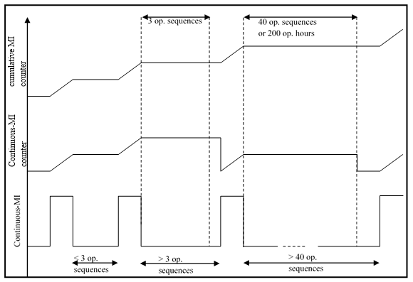
Figure C2
Illustration of the B1 counter activation principles

4.6.5.1.2. Cumulative continuous-MI counter
The OBD system shall contain a cumulative continuous-MI counter to record the cumulative number of hours during which the internal combustion engine has been operated over its life while a continuous-MI is activated.
The cumulative continuous-MI counter shall count up to the maximum value provided in a 2-byte counter with 1 hour resolution and hold that value.
The cumulative continuous-MI counter shall not be reset to zero by the engine system, a scan tool or a disconnection of a battery.
The cumulative continuous-MI counter shall operate as follows:
(a) The cumulative continuous-MI counter shall begin counting when the continuous-MI is activated;
(b) The cumulative continuous-MI counter shall halt and hold its present value when the continuous-MI is no longer activated;
(c) The cumulative continuous-MI counter shall continue counting from the point it had been held when a continuous-MI is activated.
Figure C1 illustrates the principle of the cumulative continuous-MI counter and Appendix 2 to this annex contains examples that illustrate the logic.
4.6.5.2. Counters associated with Class B1 malfunctions
4.6.5.2.1. Single B1-counter
The OBD system shall contain a B1 counter to record the number of hours during which the internal combustion engine has operated while a Class B1 malfunction is present.
The B1 counter shall operate as follows:
(a) The B1 counter shall begin counting as soon as a Class B1 malfunction is detected and a confirmed and active DTC has been stored;
(b) The B1 counter shall halt and hold its present value if no Class B1 malfunction is confirmed and active, or when all Class B1 malfunction have been erased by a scan tool;
(c) The B1 counter shall continue counting from the point it had been held if a subsequent Class B1 malfunction is detected within 3 operating sequences.
In the case where the B1 counter has exceeded 200 engine running hours, the OBD system shall set the counter to 190 engine running hours when the OBD system has determined that a Class B1 malfunction is no longer confirmed and active, or when all Class B1 malfunctions have been erased by a scan tool. The B1 counter shall begin counting from 190 engine running hours if a subsequent Class B1 malfunction is present within 3 operating sequences.
The B1 counter shall be reset to zero when three consecutive operating sequences have occurred during which no Class B1 malfunctions have been detected.
Note: The B1 counter does not indicate the number of engine running hours with a single Class B1 malfunction present.
The B1 counter may accumulate the number of hours of 2 or more different Class B1 malfunctions, none of them having reached the time the counter indicates.
The B1 counter is only intended to determine when the continuous-MI shall be activated.
Figure C2 illustrates the principle of the B1 counter and Appendix 2 to this annex contains examples that illustrate the logic.
4.6.5.2.2. Multiple B1-counters
A manufacturer may use multiple B1 counters. In that case the system shall be capable of assigning a specific B1 counter to each Class B1 malfunction.
The control of the specific B1 counter shall follow the same rules as the single B1 counter, where each specific B1 counter shall begin counting when the assigned Class B1 malfunction is detected.
4.7. OBD information
4.7.1. Recorded information
The information recorded by the OBD system shall be available upon off-board request in the following packages manner:
(a) Information about the engine state;
(b) Information about active emission-related malfunctions;
(c) Information for repair.
4.7.1.1. Information about the engine state
This information will provide an enforcement agency[35] with the malfunction indicator status and associated data (e.g. continuous-MI counter, readiness).
The OBD system shall provide all information (according to the applicable standard set in Appendix 6 to this annex) for the external roadside check test equipment to assimilate the data and provide an enforcement agent with the following information:
(a) Discriminatory/non-discriminatory display strategy;
(b) The VIN (vehicle identification number);
(c) Presence of a continuous-MI;
(d) The readiness of the OBD system;
(e) The number of engine operating hours during which a continuous-MI was last activated (continuous-MI counter).
This information shall be read only access (i.e. no clearing).
4.7.1.2. Information about active emission-related malfunctions
This information will provide any inspection station[36] with a subset of engine related OBD data including the malfunction indicator status and associated data (MI counters), a list of active/confirmed malfunctions of classes A and B and associated data (e.g. B1-counter).
The OBD system shall provide all information (according to the applicable standard set in Appendix 6 to this annex) for the external inspection test equipment to assimilate the data and provide an inspector with the following information:
(a) The gtr (and revision) number, to be integrated into Regulation No. 49 type approval marking;
(b) Discriminatory/ non-discriminatory display strategy;
(c) The VIN (vehicle identification number);
(d) The Malfunction Indicator status;
(e) The Readiness of the OBD system;
(f) Number of warm-up cycles and number of engine operating hours since recorded OBD information was last cleared;
(g) The number of engine operating hours during which a continuous-MI was last activated (continuous-MI counter);
(h) The cumulated operating hours with a continuous-MI (cumulative continuous-MI counter);
(i) The value of the B1 counter with the highest number of engine operating hours;
(j) The confirmed and active DTCs for Class A malfunctions;
(k) The confirmed and active DTCs for Classes B (B1 and B2) malfunctions;
(l) The confirmed and active DTCs for Class B1 malfunctions;
(m) The software calibration identification(s);
(n) The calibration verification number(s).
This information shall be read only access (i.e. no clearing).
4.7.1.3. Information for repair
This information will provide repair technicians with all OBD data specified in this annex (e.g. freeze frame information).
The OBD system shall provide all information (according to the applicable standard set in Appendix 6 to this annex) for the external repair test equipment to assimilate the data and provide a repair technician with the following information:
(a) gtr (and revision) number, to be integrated into Regulation No. 49 type approval marking;
(b) VIN (vehicle identification number);
(c) Malfunction indicator status;
(d) Readiness of the OBD system;
(e) Number of warm-up cycles and number of engine operating hours since recorded OBD information was last cleared;
(f) Monitor status (i.e. disabled for the rest of this drive cycle complete this drive cycle, or not complete this drive cycle) since last engine shut-off for each monitor used for readiness status;
(g) Number of engine operating hours since the malfunction indicator has been activated (continuous MI counter);
(h) Confirmed and active DTCs for Class A malfunctions;
(i) Confirmed and active DTCs for Classes B (B1 and B2) malfunctions;
(j) Cumulated operating hours with a continuous-MI (cumulative continuous-MI counter);
(k) Value of the B1 counter with the highest number of engine operating hours;
(l) Confirmed and active DTCs for Class B1 malfunctions and the number of engine operating hours from the B1-counter(s);
(m) Confirmed and active DTCs for Class C malfunctions;
(n) Pending DTCs and their associated class;
(o) Previously active DTCs and their associated class;
(p) Real-time information on OEM selected and supported sensor signals, internal and output signals (see paragraph 4.7.2. and Appendix 5 to this annex);
(q) Freeze frame data required by this annex (see paragraph 4.7.1.4. and Appendix 5 to this annex);
(r) Software calibration identification(s);
(s) Calibration verification number(s).
The OBD system shall clear all the recorded malfunctions of the engine system and related data (operating time information, freeze frame, etc.) in accordance with the provisions of this annex, when this request is provided via the external repair test equipment according to the applicable standard set in Appendix 6 to this annex.
4.7.1.4. Freeze frame information
At least one "freeze frame" of information shall be stored at the time that either a potential DTC or a confirmed and active DTC is stored at the decision of the manufacturer. The manufacturer is allowed to update the freeze frame information whenever the pending DTC is detected again.
The freeze frame shall provide the operating conditions of the vehicle at the time of malfunction detection and the DTC associated with the stored data. The freeze frame shall include the information as shown in Table 1 in Appendix 5 to this annex. The freeze frame shall also include all of the information in Tables 2 and 3 of Appendix 5 to this annex that are used for monitoring or control purposes in the specific control unit that stored the DTC.
Storage of freeze frame information associated with a Class A malfunction shall take precedence over information associated with a Class B1 malfunction which shall take precedence over information associated with a Class B2 malfunction and likewise for information associated with a Class C malfunction. The first malfunction detected shall take precedence over the most recent malfunction unless the most recent malfunction is of a higher class.
In case a device is monitored by the OBD system and is not be covered by Appendix 5 to this annex the freeze frame information shall include elements of information for the sensors and actuators of this device in a way similar to those described in Appendix 5 to this annex. This shall be submitted for approval by the Type Approval Authority at the time of approval.
4.7.1.5. Readiness
With the exceptions specified in paragraphs 4.7.1.5.1., 4.7.1.5.2. and 4.7.1.5.3., a readiness shall only be set to "complete" when a monitor or a group of monitors addressed by this status have run and concluded the presence (that means stored a confirmed and active DTC) or the absence of the failure relevant to that monitor since the last erasing by an external request or command (for example through an OBD scan-tool). Readiness shall be set to "not complete" by erasing the fault code memory (see paragraph 4.7.4.) by an external request or command (for example through an OBD scan-tool).
Normal engine shutdown shall not cause the readiness to change.
4.7.1.5.1. The manufacturer may request, subject to approval by the Type Approval Authority, the ready status for a monitor to be set to indicate "complete" without the monitor having run and concluded the presence or the absence of the failure relevant to that monitor.
Such a request may only be approved if during a multiple number of operating sequences (minimum 9 operating sequences or 72 operation hours):
(a) Monitoring is temporarily disabled according to paragraph 5.2. of this annex due to the continued presence of extreme operating conditions (e.g. cold ambient temperatures, high altitudes); or
(b) The system that is monitored is not in operation and the DTC associated to that system does not have the confirmed and active or the previously active status at the time when the readiness status becomes incomplete during a repair.
Any such request must specify the conditions for monitoring system disablement and the number of operating sequences that would pass without monitor completion before ready status would be indicated as "complete".
The extreme ambient or altitude conditions considered in the manufacturer's request shall never be less severe than the conditions specified by this annex for temporary disablement of the OBD system."
4.7.1.5.2. Monitors subject to readiness
Readiness shall be supported for each of the monitors or groups of monitors that are identified in this annex and that are required when and by referring to this annex, with the exception of items 11 and 12 of Appendix 3 to this annex.
4.7.1.5.3. Readiness for continuous monitors
Readiness of each of the monitors or groups of monitors that are identified in items 1, 7 and 10 of Appendix 3 to this annex, required when and by referring to this annex, and that are considered by this annex as running continuously, shall always indicate "complete".
4.7.2. Data stream information
The OBD system shall make available to a scan tool in real time the information shown in Tables 1 to 4 in Appendix 5 to this annex, upon request (actual signal values should be used in favour of surrogate values).
For the purpose of the calculated load and torque parameters, the OBD system shall report the most accurate values that are calculated within the applicable electronic control unit (e.g. the engine control computer).
Table 1 in Appendix 5 to this annex gives the list of mandatory OBD information relating to the engine load and speed.
Table 3 in Appendix 5 to this annex shows the other OBD information which must be included if used by the emission or OBD system to enable or disable any OBD monitors.
Table 4 in Appendix 5 to this annex shows the information which is required to be included if the engine is so equipped, senses or calculates the information[37]. At the decision of the manufacturer, other freeze frame or data stream information may be included.
In case a device is monitored by the OBD system and is not covered by Appendix 5 to this annex (e.g. SCR), the data-stream information shall include elements of information for the sensors and actuators of this device in a way similar to those described in Appendix 5 to this annex. This shall be submitted for approval by the Type Approval Authority at the time of approval.
4.7.3. Access to OBD information
Access to OBD information shall be provided only in accordance with the standards mentioned in Appendix 6 to this annex and the following sub-paragraphs.
Access to the OBD information shall not be dependent on any access code or other device or method obtainable only from the manufacturer or its suppliers. Interpretation of the OBD information shall not require any unique decoding information, unless that information is publicly available.
A single access method (e.g. a single access point/node) to OBD information shall be supported to retrieve all OBD information. This method shall permit access to the complete OBD information required by this annex. This method shall also permit access to specific smaller information packages as defined in this annex (e.g. road worthiness information packages in case of emission related OBD).
Access to OBD information shall be provided using at least one of the following series of standards mentioned in Appendix 6 to this annex:
(a) ISO 27145 with ISO 15765-4 (CAN-based);
(b) ISO 27145 with ISO 13400 (TCP/IP-based);
(c) SAE J1939-73.
Manufacturers shall use appropriate ISO or SAE-defined fault codes (for example, P0xxx, P2xxx, etc.) whenever possible. If such identification is not possible, the manufacturer may use diagnostic trouble codes according to the relevant clauses in ISO 27145 or SAE J1939. The fault codes must be fully accessible by standardized diagnostic equipment complying with the provisions of this annex.
The manufacturer shall provide the ISO or SAE standardization body through the appropriate ISO or SAE process with emission-related diagnostic data not specified by ISO 27145 or SAE J1939 but related to this annex.
Access to OBD information shall be possible by the means of a wired connection.
OBD data shall be provided by the OBD system upon request using scan tool that complies with the requirements of the applicable standards mentioned in Appendix 6 to this annex (communication with external tester).
4.7.3.1. CAN based wired communication
The communication speed on the wired data link of the OBD system shall be either 250 kbps or 500 kbps.
It is the manufacturer's responsibility to select the baud-rate and to design the OBD system according to the requirements specified in the standards mentioned in Appendix 6 to this annex, and referred to in this annex. The OBD system shall be tolerant against the automatic detection between these two baud-rates exercised by the external test equipment.
The connection interface between the vehicle and the external diagnostic test equipment (e.g. scan-tool) shall be standardised and shall meet all of the requirements of ISO 15031‑3 Type A (12 VDC power supply), Type B (24 VDC power supply) or SAE J1939-13 (12 or 24 VDC power supply).
4.7.3.2. Reserved for TCP/IP (Ethernet) based wired communication.
4.7.3.3. Connector location
The connector shall be located in the driver's side foot-well region of the vehicle interior in the area bound by the driver's side of the vehicle and the driver's side edge of the centre console (or the vehicle centreline if the vehicle does not have a centre console) and at a location no higher than the bottom of the steering wheel when in the lowest adjustable position. The connector may not be located on or in the centre console (i.e. neither on the horizontal faces near the floor-mounted gear selector, parking brake lever, or cup holders nor on the vertical faces near the stereo/radio, climate system, or navigation system controls). The location of the connector shall be capable of being easily identified and accessed (e.g. to connect an off-board tool). For vehicles equipped with a driver's side door, the connector shall be capable of being easily identified and accessed by someone standing (or "crouched") outside the driver's side of the vehicle with the driver's side door open.
The Type Approval Authority may approve upon request of the manufacturer an alternative location provided the installation position shall be easily accessible and protected from accidental damage during normal conditions of use, e.g. the location as described in ISO 15031 series of standards.
If the connector is covered or located in a specific equipment box, the cover or the compartment door must be removable by hand without the use of any tools and be clearly labelled "OBD" to identify the location of the connector.
The manufacturer may equip vehicles with additional diagnostic connectors and data-links for manufacturer-specific purposes other than the required OBD functions. If the additional connector conforms to one of the standard diagnostic connectors allowed in Appendix 6 to this annex, only the connector required by this annex shall be clearly labelled "OBD" to distinguish it from other similar connectors.
4.7.4. Erasing / resetting OBD information by a scan-tool
On request of the scan tool, the following data shall be erased or reset to the value specified in this annex from the computer memory.
OBD information data | Erasable | Resetable |
Malfunction indicator status | | X |
Readiness of the OBD system | | X |
Number of engine operating hours since the malfunction indicator has been activated (continuous MI counter) | X | |
All DTCs | X | |
The value of the B1 counter with the highest number of engine operating hours | | X |
The number of engine operating hours from the B1-counter(s) | | X |
The freeze frame data requested by this annex | X | |
OBD information shall not be erased by disconnection of the vehicle's battery(s).
4.8. Electronic security
Any vehicle with an emission control unit must include features to deter modification, except as authorized by the manufacturer. The manufacturer shall authorize modifications if these modifications are necessary for the diagnosis, servicing, inspection, retrofitting or repair of the vehicle.
Any reprogramable computer codes or operating parameters shall be resistant to tampering and afford a level of protection at least as good as the provisions in ISO 15031‑7 (SAE J2186) or J1939-73 provided that the security exchange is conducted using the protocols and diagnostic connector as prescribed in this annex. Any removable calibration memory chips shall be potted, encased in a sealed container or protected by electronic algorithms and shall not be changeable without the use of specialised tools and procedures.
Computer-coded engine operating parameters shall not be changeable without the use of specialised tools and procedures (e.g. soldered or potted computer components or sealed (or soldered) computer enclosures).
Manufacturers shall take adequate steps to protect the maximum fuel delivery setting from tampering while a vehicle is in-service.
Manufacturers may apply to the Type Approval Authority for an exemption from one of these requirements for those vehicles that are unlikely to require protection. The criteria that the Type Approval Authority will evaluate in considering an exemption will include, but are not limited to, the current availability of performance chips, the high-performance capability of the vehicle and the projected sales volume of the vehicle.
Manufacturers using programmable computer code systems (e.g. electrical erasable programmable read-only memory, EEPROM) shall deter unauthorized reprogramming. Manufacturers shall include enhanced tamper-protection strategies and write protect features requiring electronic access to an off-site computer maintained by the manufacturer. Alternative methods giving an equivalent level of tamper protection may be approved by the Type Approval Authority
4.9. Durability of the OBD system
The OBD system shall be designed and constructed so as to enable it to identify types of malfunctions over the complete life of the vehicle or engine system.
Any additional provisions addressing the durability of OBD systems are contained in this annex.
An OBD system shall not be programmed or otherwise designed to partially or totally deactivate based on age and/or mileage of the vehicle during the actual life of the vehicle, nor shall the system contain any algorithm or strategy designed to reduce the effectiveness of the OBD system over time.
5. Performance requirements
5.1. Thresholds
The OTLs for the applicable monitoring criteria defined in Appendix 3 to this annex are defined in the main part of this Regulation
5.2. Temporary disablement of the OBD system
Approval authorities may approve that an OBD system be temporarily disabled under the conditions specified in the following sub-paragraphs.
At the time of type approval, the manufacturer shall provide the Type Approval Authority with the detailed description of each of the OBD system's temporary disablement strategies and the data and/or engineering evaluation demonstrating that monitoring during the applicable conditions would be unreliable or impractical.
In all cases, monitoring shall resume once the conditions justifying temporary disablement are no longer present.
5.2.1. Engine/vehicle operational safety
Manufacturers may request approval to disable the affected OBD monitoring systems when operational safety strategies are activated.
The OBD monitoring system is not required to evaluate components during malfunction if such evaluation would result in a risk to the safe use of the vehicle.
5.2.2. Ambient temperature and altitude conditions
Manufacturers may request approval to disable OBD system monitors:
(a) At ambient temperatures below 266 K (-7 degrees Celsius) in the case where the coolant temperature has not reached a minimum temperature of at least 333 K (60 degrees Celsius); or
(b) At ambient temperatures below 266K (-7 degrees Celsius) in the case of frozen reagent; or
(c) At ambient temperatures above 308 K (35 degrees Celsius); or
(d) At elevations above 2,500 meters above sea level; or
(e) Below 400 meters under sea level; or
(f) With the exception of electrical circuit failures, at ambient temperatures below 251 K (-22 degrees Celsius).
A manufacturer may further request approval that an OBD system monitor be temporarily disabled at other ambient temperatures and altitude conditions upon determining that the manufacturer has demonstrated with data and/or an engineering evaluation that misdiagnosis would occur at those ambient conditions because of its effect on the component itself (e.g. component freezing, effect on the compatibility with sensor tolerances).
Note: Ambient conditions may be estimated by indirect methods. For example ambient temperature conditions may be determined based on intake air temperature.
5.2.3. Low fuel level
Manufacturers may request approval to disable monitoring systems that are affected by low fuel level / pressure or running out of fuel (e.g. diagnosis of a malfunction of the fuelling system or misfiring) as follows:
| Diesel | Gas |
| NG | LPG |
(a) The low fuel level considered for such a disablement shall not exceed 100 litres or 20 per cent of the nominal capacity of the fuel tank, whichever is lower. | X | | X |
(b) The low fuel pressure in the tank considered for such a disablement shall not exceed 20 per cent of the usable range of fuel tank pressure. | | X | |
5.2.4. Vehicle battery or system voltage levels
Manufacturers may request approval to disable monitoring systems that can be affected by vehicle battery or system voltage levels.
5.2.4.1. Low voltage
For monitoring systems affected by low vehicle battery or system voltages, manufacturers may request approval to disable monitoring systems when the battery or system voltage is below 90 per cent of the nominal voltage (or 11.0 volts for a 12 volt battery, 22.0 volts for a 24 volt battery). Manufacturers may request approval to utilize a voltage threshold higher than this value to disable system monitoring.
The manufacturer shall demonstrate that monitoring at the voltages would be unreliable and that either operation of a vehicle below the disablement criteria for extended periods of time is unlikely or the OBD system monitors the battery or system voltage and will detect a malfunction at the voltage used to disable other monitors.
5.2.4.2. High voltage
For emission related monitoring systems affected by high vehicle battery or system voltages, manufacturers may request approval to disable monitoring systems when the battery or system voltage exceeds a manufacturer-defined voltage.
The manufacturer shall demonstrate that monitoring above the manufacturer-defined voltage would be unreliable and that either the electrical charging system/alternator warning light is illuminated (or voltage gauge is in the "red zone") or the OBD system monitors the battery or system voltage and will detect a malfunction at the voltage used to disable other monitors.
5.2.5. Active PTO (power take-off units)
The manufacturer may request approval to temporarily disable affected monitoring systems in vehicles equipped with a PTO unit, under the condition where that PTO unit is temporarily active.
5.2.6. Forced regeneration
The manufacturer may request approval to disable the affected OBD monitoring systems during the forced regeneration of an emission control system downstream of the engine (e.g. a particulate filter).
5.2.7. Auxillary Emissions Strategy (AES)
The manufacturer may request approval to disable OBD system monitors during the operation of an AES, including MECS, under conditions not already covered in paragraph 5.2. if the monitoring capability of a monitor is affected by the operation of an AES.
5.2.8. Re-fuelling
After a refuelling, the manufacturer of a gaseous-fuelled vehicle may temporarily disable the OBD system when the system has to adapt to the recognition by the ECU of a change in the fuel quality and composition.
The OBD system shall be re-enabled as soon as the new fuel is recognized and the engine parameters are readjusted. This disablement shall be limited to a maximum of 10 minutes.
6. Demonstration requirements
The basic elements for demonstrating the compliance of an OBD system with the requirements of this annex are as follows:
(a) Procedure for selecting the OBD-parent engine system. The OBD-parent engine system is selected by the manufacturer in agreement with the Type Approval Authority;
(b) Procedure for demonstrating the classification of a malfunction. The manufacturer submits to the Type Approval Authority the classification of each malfunction for that OBD-parent engine system and the necessary supporting data in order to justify each classification;
(c) Procedure for qualifying a deteriorated component. The manufacturer shall provide, on request of the Type Approval Authority, deteriorated components for OBD testing purposes. These components are qualified on the basis of supporting data provided by the manufacturer;
(d) Procedure for selecting the reference fuel in case of a gas engine.
6.1. Emission-OBD family
The manufacturer is responsible for determining the composition of an emission-OBD family. Grouping engine systems within an emission-OBD family shall be based on good engineering judgement and be subject to approval by the Type Approval Authority.
Engines that do not belong to the same engine family may still belong to the same emission-OBD family.
6.1.1. Parameters defining an emission-OBD family
An emission-OBD family is characterised by basic design parameters that shall be common to engine systems within the family.
In order that engine systems are considered to belong to the same OBD-engine family, the following list of basic parameters shall be similar:
(a) Emission control systems;
(b) Methods of OBD monitoring;
(c) Criteria for performance and component monitoring;
(d) Monitoring parameters (e.g. frequency).
These similarities shall be demonstrated by the manufacturer by means of relevant engineering demonstration or other appropriate procedures and subject to the approval of the Type Approval Authority.
The manufacturer may request approval by the Type Approval Authority of minor differences in the methods of monitoring/diagnosing the engine emission control system due to engine system configuration variation, when these methods are considered similar by the manufacturer and:
(a) They differ only to match specificities of the considered components (e.g. size, exhaust flow, etc.); or
(b) Their similarities are based on good engineering judgement.
6.1.2. OBD-parent engine system
Compliance of an emission-OBD family with the requirements of this annex is achieved by demonstrating the compliance of the OBD-parent engine system of this family.
The selection of the OBD-parent engine system is made by the manufacturer and subject to the approval of the Type Approval Authority.
Prior to testing the Type Approval Authority may decide to request the manufacturer to select an additional engine for demonstration.
The manufacturer may also propose to the Type Approval Authority to test additional engines to cover the complete emission-OBD family.
6.2. Procedures for demonstrating the malfunction classification
The manufacturer shall provide the documentation justifying the proper classification of each malfunction to the Type Approval Authority. This documentation shall include a failure analysis (for example elements of a "failure mode and effect analysis") and may also include:
(a) Simulation results;
(b) Test results;
(c) Reference to previously approved classification.
In the following paragraphs the requirements for demonstrating the correct classification are listed, including requirements for testing. The minimum number of tests is four and the maximum number of tests is four times the number of engine families considered within the emission OBD family. The Type Approval Authority may decide to curtail the test at any time before this maximum number of failure tests has been reached.
In specific cases where the classification testing is not possible (for example, if an MECS is activated and the engine cannot run the applicable test, etc.), the malfunction may be classified based on technical justification. This exception shall be documented by the manufacturer and is subject to the agreement of the Type Approval Authority.
6.2.1. Demonstration of classification into Class A
The classification by the manufacturer of a malfunction into Class A shall not be subject to a demonstration test.
If the Type Approval Authority disagrees with a manufacturer's classification of a malfunction as Class A, the Type Approval Authority requires the classification of the malfunction into Class B1, B2 or C, as appropriate.
In that case the approval document shall record that the malfunction classification has been assigned according to the request of the Type Approval Authority.
6.2.2. Demonstration of classification into Class B1 (distinguishing between A and B1)
In order to justify the classification of a malfunction into Class B1 the documentation shall clearly demonstrate that, in some circumstances, the malfunction results in emissions that are lower than the OTLs.
In the case that the Type Approval Authority requires an emission test for demonstrating the classification of a malfunction into Class B1 the manufacturer shall demonstrate that the emissions due to that particular malfunction are, in selected circumstances, below the OTLs:
(a) The manufacturer selects the circumstances of the test in agreement with the Type Approval Authority;
(b) The manufacturer shall not be required to demonstrate that in other circumstances the emissions due to the malfunction are actually above the OTLs.
If the manufacturer fails to demonstrate the classification as Class B1, the malfunction is classified as Class A.
6.2.3. Demonstration of classification into Class B1 (distinguishing between B2 and B1)
If the Type Approval Authority disagrees with a manufacturer's classification of a malfunction as Class B1 because it considers that the OTLs are not exceeded, the Type Approval Authority requires the reclassification of that malfunction into Class B2 or C. In that case the approval documents shall record that the malfunction classification has been assigned according to the request of the Type Approval Authority.
6.2.4. Demonstration of classification into Class B2 (distinguishing between B2 and B1)
In order to justify the classification of a malfunction into Class B2 the manufacturer shall demonstrate that emissions are lower than the OTLs.
In case the Type Approval Authority disagrees with the classification of a malfunction as Class B2 because it considers that the OTLs are exceeded, the manufacturer may be required to demonstrate by testing that the emissions due to the malfunction are below the OTLs. If the test fails, then the Type Approval Authority shall require the reclassification of that malfunction into A or B1 and the manufacturer shall subsequently demonstrate the appropriate classification and the documentation shall be updated.
6.2.5. Demonstration of classification into Class B2 (distinguishing between B2 and C)
If the Type Approval Authority disagrees with a manufacturer's classification of a malfunction as Class B2 because it considers the regulated emission limits are not exceeded, the Type Approval Authority requires the reclassification of that malfunction into Class C. In that case the approval documents shall record that the malfunction classification has been assigned according to the request of the Type Approval Authority.
6.2.6. Demonstration of classification into Class C
In order to justify the classification of a malfunction into Class C the manufacturer shall demonstrate that emissions are lower than the regulated emission limits.
In case the Type Approval Authority disagrees with the classification of a malfunction as Class C the manufacturer may be required to demonstrate by testing that the emissions due to the malfunction are below the regulated emission limits.
If the test fails, then the Type Approval Authority shall request the reclassification of that malfunction and the manufacturer shall subsequently demonstrate the appropriate reclassification and the documentation shall be updated.
6.3. Procedures for demonstrating the OBD performance
The manufacturer shall submit to the Type Approval Authority a complete documentation package justifying the compliance of the OBD system as regards its monitoring capability, which may include:
(a) Algorithms and decision charts;
(b) Tests and/or simulation results;
(c) Reference to previously approved monitoring systems, etc.
In the following paragraphs the requirements for demonstrating the OBD performance are listed, including requirements for testing. The number of tests shall be four times the number of engine families considered within the emission OBD family, but shall not be less than eight.
The monitors selected shall reflect the different types of monitors mentioned in paragraph 4.2. (i.e. emission threshold monitoring, performance monitoring, total functional failure monitoring, or component monitoring) in a well balanced manner. The monitors selected shall also reflect the different items listed in Appendix 3 to this annex in a well balanced manner.
6.3.1. Procedures for demonstrating the OBD performance by testing
In addition to the supporting data referred to in paragraph 6.3., the manufacturer shall demonstrate the proper monitoring of specific emission control systems or components by testing them on an engine test-bed according to the test procedures specified in paragraph 7.2. of this annex.
In that case, the manufacturer shall make available the qualified deteriorated components or the electrical device which would be used to simulate a malfunction.
The proper detection of the malfunction by the OBD system and its proper response to that detection (cf. MI indication, DTC storage, etc.) shall be demonstrated according to paragraph 7.2.
6.3.2. Procedures for qualifying a deteriorated component (or system)
This paragraph applies to the cases where the malfunction selected for an OBD demonstration test is monitored against tailpipe emissions (emission threshold monitoring - see paragraph 4.2.) and it is required that the manufacturer demonstrates, by an emission test, the qualification of that deteriorated component.
In very specific cases the qualification of deteriorated components or systems by testing may not be possible (for example, if an MECS is activated and the engine cannot run the applicable test, etc.). In such cases, the deteriorated component shall be qualified without testing. This exception shall be documented by the manufacturer and is subject to the agreement of the Type Type Approval Authority.
6.3.2.1. Procedure for qualifying a deteriorated component used to demonstrate the detection of classes A and B1 malfunctions
6.3.2.1.1. Emission threshold monitoring
In the case the malfunction selected by the Type Approval Authority results in tailpipe emissions that may exceed an OBD threshold limit, the manufacturer shall demonstrate by an emission test according to paragraph 7. that the deteriorated component or device does not result in the relevant emission exceeding its OTL by more than 20 per cent.
6.3.2.1.2. Performance monitoring
At the request of the manufacturer and with the agreement of the Type Approval Authority, in the case of performance monitoring, the OTL may be exceeded by more than 20 per cent. Such request shall be justified on a case by case basis.
In the case when the performance monitoring of an abnormality of the gaseous fuel consumption of a dual-fuel engine or vehicle is required by Annex 15, a deteriorated component is qualified without reference to the OTL.
6.3.2.1.3. Component monitoring
In the case of component monitoring, a deteriorated component is qualified without reference to the OTL.
6.3.2.2. Qualification of deteriorated components used to demonstrate the detection of Class B2 malfunctions
In the case of Class B2 malfunctions, and upon request of the Type Approval Authority, the manufacturer shall demonstrate by an emission test according to paragraph 7. that the deteriorated component or device does not lead the relevant emission to exceed its applicable OTL.
6.3.2.3. Qualification of deteriorated components used to demonstrate the detection of Class C malfunctions
In the case of Class C malfunctions, and upon request of the Type Approval Authority, the manufacturer shall demonstrate by an emission test according to paragraph 7. that the deteriorated component or device does not lead the relevant emission to exceed its applicable regulated emission limit.
6.3.3. Test report
The test report shall contain, at a minimum, the information set out in Appendix 4 to this annex.
6.4. Approval of an OBD system containing deficiencies
6.4.1. Approval authorities may approve upon request of a manufacturer an OBD system even though the system contains one or more deficiencies.
In considering the request, the Type Approval Authority shall determine whether compliance with the requirements of this annex is feasible or unreasonable.
The Type Approval Authority shall take into consideration data from the manufacturer that details such factors as, but not limited to, technical feasibility, lead time and production cycles including phase-in or phase-out of engines designs and programmed upgrades of computers, the extent to which the resultant OBD system will be effective in complying with the requirements of this annex and that the manufacturer has demonstrated an acceptable level of effort toward meeting the requirements of the annex.
The Type Approval Authority will not accept any deficiency request that includes the complete lack of a required diagnostic monitor (i.e. a complete lack of the monitors required in Appendix 3 to this annex).
6.4.2. Deficiency period
A deficiency is granted for a period of one year after the date of approval of the engine system.
If the manufacturer can adequately demonstrate to the Type Approval Authority that substantial engine modifications and additional lead time would be necessary to correct the deficiency, then this deficiency can be granted again for an additional one year, provided that the total deficiency period does not exceed three years (i.e. three times one year deficiency allowance is permitted).
The manufacturer cannot apply for a renewal of the deficiency period.
6.5. Procedure for selecting the reference fuel in case of a gas engine
Demonstration of the OBD performance and malfunction classification shall be performed by using one of the reference fuels mentioned in Annex 5 on which the engine is designed to operate.
The selection of this reference fuel is done by the Type Approval Authority , who shall provide sufficient time for the test laboratory to supply the selected reference fuel.
7. Test procedures
7.1. Testing process
The demonstration by testing of the proper malfunction classification and the demonstration by testing of the proper monitoring performance of an OBD system are issues that shall be considered separately during the testing process. For example, a Class A malfunction will not require a classification test while it may be subject to an OBD performance test.
Where appropriate, the same test may be used to demonstrate the correct classification of a malfunction, the qualification of a deteriorated component provided by the manufacturer and the correct monitoring by the OBD system.
The engine system on which the OBD system is tested shall comply with the emission requirements of this Regulation.
7.1.1. Testing process for demonstrating the malfunction classification
When, according to paragraph 6.2., the Type Approval Authority requests the manufacturer to justify by testing the classification of a specific malfunction, the compliance demonstration will consist of a series of emission tests.
According to paragraph 6.2.2., when testing is required by the Type Approval Authority to justify the classification of a malfunction into Class B1 rather than in Class A, the manufacturer shall demonstrate that the emissions due to that particular malfunction are, in selected circumstances, below the OTLs:
(a) The manufacturer selects these circumstances of test in agreement with the Type Approval Authority;
(b) The manufacturer shall not be required to demonstrate that in other circumstances the emissions due to the malfunction are actually above the OTLs.
The emission test may be repeated upon request of the manufacturer up to three times.
If any of these tests leads to emissions below the considered OTL, then the malfunction classification into Class B1 shall be approved.
When testing is required by the Type Approval Authority to justify the classification of a malfunction into Class B2 rather than in Class B1 or into Class C rather than in Class B2, the emission test shall not be repeated. If the emissions measured in the test are above the OTL or the emission limit, respectively, then the malfunction shall require a reclassification.
Note: According to paragraph 6.2.1., this paragraph does not apply to malfunctions classified into Class A.
7.1.2. Testing process for demonstrating the OBD performance
When the Type Approval Authority requests to test the OBD system performance according to paragraph 6.3., the compliance demonstration shall consist of the following phases:
(a) A malfunction is selected by the Type Approval Authority and a corresponding deteriorated component or system shall be made available by the manufacturer;
(b) When appropriate and if requested, the manufacturer shall demonstrate by an emission test that the deteriorated component is qualified for a monitoring demonstration;
(c) The manufacturer shall demonstrate that the OBD system responds in a manner that complies with the provisions of this annex (i.e. MI indication, DTC storage, etc.) At the latest by the end of a series of OBD test-cycles.
7.1.2.1. Qualification of the deteriorated component
When the Type Approval Authority requests the manufacturer to qualify a deteriorated component by testing according to paragraph 6.3.2., this demonstration shall be made by performing an emissions test.
If it is determined that the installation of a deteriorated component or device on an engine system means that a comparison with the OBD threshold limits is not possible (e.g. because the statistical conditions for validating the applicable emission test cycle are not met), the malfunction of that component or device may be considered as qualified upon the agreement of the Type Approval Authority based on technical rationale provided by the manufacturer.
In the case that the installation of a deteriorated component or device on an engine means that the full load curve (as determined with a correctly operating engine) cannot be attained during the test, the deteriorated component or device may be considered as qualified upon the agreement of the Type Approval Authority based on technical rationale provided by the manufacturer.
7.1.2.2. Malfunction detection
Each monitor selected by the Type Approval Authority to be tested on an engine test-bed, shall respond to the introduction of a qualified deteriorated component in a manner that meets the requirements of this annex within two consecutive OBD test-cycles according to paragraph 7.2.2. of this annex.
When it has been specified in the monitoring description and agreed by the Type Approval Authority that a specific monitor needs more than two operating sequences to complete its monitoring, the number of OBD test-cycles may be increased according to the manufacturer's request.
Each individual OBD test-cycle in the demonstration test shall be separated by an engine shut-off. The time until the next start-up shall take into consideration any monitoring that may occur after engine shut-off and any necessary condition that must exist for monitoring to occur at the next start up.
The test is considered complete as soon as the OBD system has responded in a manner that meets the requirements of this annex.
7.2. Applicable tests
In the context of this annex:
(a) The emission test-cycle is the test-cycle used for the measurement of the regulated emissions when qualifying a deteriorated component or system;
(b) The OBD test-cycle is the test-cycle used to demonstrate the capacity of the OBD monitors to detect malfunctions.
7.2.1. Emission test cycle
The test-cycle considered in this annex for measuring emissions is the WHTC test-cycle as described in Annex 4.
7.2.2. OBD test cycle
The OBD test-cycle considered in this annex is the hot part of the WHTC cycle as described in Annex 4.
On request of the manufacturer and after approval of the Type Approval Authority , an alternative OBD test-cycle can be used (e.g. the cold part of the WHTC cycle) for a specific monitor. The request shall contain documentation (technical considerations, simulation, test results, etc.) showing that:
(a) The requested test-cycle appropriate to demonstrate monitoring occurs under real world driving conditions; and
(b) The hot part of the WHTC cycle appears as less appropriate for the considered monitoring (e.g. fluid consumption monitoring).
7.2.3. Test operating conditions
The conditions (i.e. temperature, altitude, fuel quality etc.) for conducting the tests referred to in paragraphs 7.2.1. and 7.2.2. shall be those required for operating the WHTC test cycle as described in Annex 4.
In the case of an emission test aimed at justifying the classification of a specific malfunction into Class B1, the test operating conditions may, per decision of the manufacturer, deviate from the ones in the paragraphs above according to paragraph 6.2.2.
7.3. Demonstration process for performance monitoring
The manufacturer may use the demonstration requirements as set out in Appendix 7 to this annex in case of performance monitoring.
Type Approval authorities may approve a manufacturer's use of a type of performance monitoring technique other than the one referred to in Appendix 7 to this annex. The chosen type of monitoring shall be demonstrated by the manufacturer by a robust technical case based upon the design characteristics, or by presentation of test results, or by reference to previous approvals, or by some other acceptable method, to be at least as robust, timely and efficient as the ones mentioned in Appendix 7 to this annex.
7.4. Test reports
The test report shall contain, at a minimum, the information set out in Appendix 4.
8. Documentation requirements
8.1. Documentation for purpose of approval
The manufacturer shall provide a documentation package that includes a full description of the OBD system. The documentation package shall be made available in two parts:
(a) A first part, which may be brief, provided that it exhibits evidence concerning the relationships between monitors, sensors/actuators, and operating conditions (i.e. describes all enable conditions for monitors to run and disable conditions that cause monitors not to run). The documentation shall describe the functional operation of the OBD, including the malfunction ranking within the hierarchical classification. This material shall be retained by the Type Approval Authority. This information may be made available to interested parties upon request;
(b) A second part containing any data, including details of qualified deteriorated components or systems and associated test results, which are used as evidence to support the decision process referred to above, and a listing of all input and output signals that are available to the engine system and monitored by the OBD system. This second part shall also outline each monitoring strategy and the decision process.
This second part shall remain strictly confidential. It may be kept by the Type Approval Authority or, at the discretion of the Type Approval Authority, may be retained by the manufacturer but shall be made open for inspection by the Type Approval Authority at the time of approval or at any time during the validity of the approval.
8.1.1. Documentation associated with each monitored component or system
The documentation package included in the second part shall contain but shall not be limited to the following information for each monitored component or system:
(a) The malfunctions and associated DTC(s);
(b) The monitoring method used for malfunction detection;
(c) The parameters used and the conditions necessary for malfunction detection and when applicable the fault criteria limits (performance and component monitoring);
(d) The criteria for storing a DTC;
(e) The monitoring "time length" (i.e. the operation time/procedure necessary to complete the monitoring) and the monitoring "frequency" (e.g. continuous, once per trip, etc.).
8.1.2. Documentation associated with the malfunction classification
The documentation package included in the second part shall contain but shall not be limited to the following information for malfunction classification:
The malfunction classification of each DTC shall be documented. This classification may be different for different engine types (e.g. different engine ratings) within the same emission-OBD family.
This information shall include the technical justification required in paragraph 4.2. of this annex for classification into Class A, Class B1 or Class B2.
8.1.3. Documentation associated with the emission-OBD family
The documentation package included in the second part shall contain but shall not be limited to the following information for emission OBD-family:
A description of the emission-OBD family shall be provided. This description shall include a list and a description of the engine types within the family, the description of the OBD-parent engine system, and all elements that characterise the family according to paragraph 6.1.1. of this annex.
In the case where the emission-OBD family includes engines belonging to different engine families, a summary description of these engine families shall be provided.
In addition, the manufacturer shall provide a list of all electronic input, output and identification of the communication protocol utilized by each emission-OBD family.
8.2. Documentation for installing in a vehicle an OBD equipped engine system
The engine manufacturer shall include in the installation documents of its engine system the appropriate requirements that will ensure the vehicle, when used on the road or elsewhere as appropriate, will comply with the requirements of this annex. This documentation shall include but is not limited to:
(a) The detailed technical requirements, including the provisions ensuring the compatibility with the OBD system of the engine system;
(b) The verification procedure to be completed.
The existence and the adequacy of such installation requirements may be checked during the approval process of the engine system.
Note: In the case a vehicle manufacturer applies for a direct approval of the installation of the OBD system on the vehicle, this documentation is not required.
Annex 9B ‑ Appendix 1 Approval of installation of OBD systems
This appendix considers the case where the vehicle manufacturer requests approval of the installation on a vehicle of (an) OBD system(s) within an emission OBD family that is (are) certified to the requirements of this annex
In this case, and in addition to the general requirements of this annex, a demonstration of the correct installation is required. This demonstration shall be done on the basis of the appropriate element of design, results of verification tests, etc. and address the conformity of the following elements to the requirements of this annex:
(a) The installation on-board the vehicle as regards its compatibility with the OBD system of the engine-system;
(b) The MI (pictogram, activation schemes, etc.);
(c) The wired communication interface.
Correct MI illumination, information storage and on-board off-board OBD communication will be checked. But any check shall not force dismounting the engine system (e.g. an electric disconnection may be selected).
Annex 9B ‑ Appendix 2 Malfunctions - Illustration of the DTC status - Illustration of the MI and counters activation schemes
This appendix aims at illustrating the requirements set in paragraphs 4.3. and 4.6.5. of this annex.
It contains the following figures:
Figure 1: DTC status in case of a Class B1 malfunction
Figure 2 DTC status in case of 2 consecutive different Class B1 malfunctions
Figure 3: DTC status in case of the re-occurrence of a Class B1 malfunction
Figure 4A: Class A malfunction -activation of the MI and MI counters
Figure 4B: Illustration of the continuous MI deactivation principle
Figure 5: Class B1 malfunction - activation of the B1 counter in 5 use cases.
Figure 1
DTC status in case of a Class B1 malfunction

Notes:
Means the point a monitoring of the concerned malfunction occurs
N, M The annex requires the identification of "key" operating sequences during which some events occurs, and the counting of the subsequent operating sequences. For the purpose of illustrating this requirement, the "key" operating sequences have been given the values N and M.
E.g. M means the first operating sequence following the detection of a potential malfunction, and N means the operating sequence during which the MI is switched OFF.
Figure 2
DTC status in case of 2 consecutive different Class B1 malfunctions

Notes:
Means the point a monitoring of the concerned malfunction occurs
N, M,
N', M' The annex requires the identification of "key" operating sequences during which some events occurs, and the counting of the subsequent operating sequences. For the purpose of illustrating this requirement, the "key" operating sequences have been given the values N and M for the first malfunction, respectively N' and M' for the second one.
E.g. M means the first operating sequence following the detection of a potential malfunction, and N means the operating sequence during which the MI is switched OFF.
N + 40 the fortieth operating sequence after the first extinction of the MI or 200 engine operating hours, whichever the earliest.
Figure 3
DTC status in case of the re-occurrence of a Class B1 malfunction

Notes:
Means the point a monitoring of the concerned malfunction occurs.
N, M,
N', M' The annex requires the identification of "key" operating sequences during which some events occurs, and the counting of the subsequent operating sequences. For the purpose of illustrating this requirement, the "key" operating sequences have been given the values N and M for the first occurrence of a malfunction, respectively N' and M' for the second one.
E.g. M means the first operating sequence following the detection of a potential malfunction, and N means the operating sequence during which the MI is switched OFF.
Figure 4A
Class A malfunction - activation of the MI and MI counters

Note: Details related to the deactivation of the continuous MI are illustrated in Figure 4B below in the specific case where a potential state is present.
Figure 4B
Illustration of the continuous MI deactivation principle
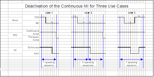
Notes:
Means the point where monitoring of the concerned malfunction occurs.
M Means the operating sequence when the monitor concludes for the first time that a confirmed and active failure is no longer present.
Case 1 Means the case where the monitor does not conclude the presence of failure during the operating sequence M.
Case 2 Means the case where the monitor has previously concluded, during the operating sequence M, the presence of the malfunction.
Case 3 Means the case where the monitor concludes during the operating sequence M the presence of the malfunction after having first concluded to its absence.
Figure 5
Class B1 malfunction - activation of the B1 counter in 5 use Cases

Note: In this example, it is assumed that there is a single B1 counter.
Annex 9B ‑ Appendix 3 Monitoring requirements
The items of this appendix list the systems or components required to be monitored by the OBD system, according to paragraph 4.2. of this annex. Unless specified otherwise, the requirements apply to all engine types.
Appendix 3 - Item 1
Electric / electronic components monitoring
Electric/electronic components used to control or monitor the emission control systems described in this appendix shall be subject to Component Monitoring according to the provisions of paragraph 4.2. of this annex. This includes, but is not limited to, pressure sensors, temperature sensors, exhaust gas sensors and oxygen sensors when present, knock sensors, in-exhaust fuel or reagent injector(s), in-exhaust burners or heating elements, glow plugs, intake air heaters.
Wherever a feedback control loop exists, the OBD system shall monitor the system's ability to maintain feedback control as designed (possible errors are for example: not entering feedback control within a manufacturer specified time interval, or: when feedback control has used up all the adjustment capability allowed by the manufacturer and the system cannot achieve the target) - component monitoring.
In particular, in the case where the control of reagent injection is performed by means of a closed loop system, the monitoring requirements set out in this item shall apply, but the failures detected shall not be classified as Class C failures.
Note: These provisions apply to all electric-electronic components, even if they belong to any of the monitors described in the other items of this appendix.
Appendix 3 - Item 2
DPF system
The OBD system shall monitor the following elements of the DPF system on engines so-equipped for proper operation:
(a) DPF substrate: the presence of the DPF substrate - total functional failure monitoring;
(b) DPF performance: clogging of the DPF - total functional failure;
(c1) DPF filtering performance: the filtering and regeneration process of the DPF. This requirement would apply to PM emissions only - emission threshold monitoring.
Alternatively, as appropriate[42], the OBD system shall monitor:
(c2) DPF performance: filtering and regeneration processes (e.g. particulate accumulation during the filtering process and particulate removal during a forced regeneration process) – performance monitoring according to Appendix 8 to this annex.
Note: The periodic regeneration shall be monitored against the ability of the device to perform as designed (for example to perform regeneration within a manufacturer-specified time interval, to perform regeneration upon demand, etc). This will constitute one element of the component monitoring associated with the device.
Appendix 3 - Item 3
Selective Catalytic Reduction (SCR) monitoring
For the purpose of this item, SCR means selective catalytic reduction or other lean NOx catalyst device. The OBD system shall monitor the following elements of the SCR system on engines so-equipped for proper operation:
(a) Active/intrusive reagent injection system: the system's ability to regulate reagent delivery properly, whether delivered via an in-exhaust injection or an in-cylinder injection - performance monitoring;
(b) Active/intrusive reagent: the on-board availability of the reagent, the proper consumption of the reagent if a reagent other than fuel is used (e.g. urea) - performance monitoring;
(c) Active/intrusive reagent: the proper consumption of the reagent if a reagent other than fuel is used (e.g. urea) - performance monitoring;
(d) SCR catalyst conversion efficiency: the catalyst's SCR ability to convert NOx emission threshold monitoring.
Appendix 3 - Item 4
Lean-NOx Trap /LNT, or NOx adsorber);
The OBD system shall monitor the following elements of the LNT system on engines so-equipped for proper operation:
(a) LNT capability: the LNT system's ability to adsorb/store and convert NOx - performance monitoring;
(b) LNT active/intrusive reagent injection system: the system's ability to regulate reagent delivery properly, whether delivered via an in-exhaust injection or an in-cylinder injection - performance monitoring.
Appendix 3 - Item 5
Oxidation catalysts (incl. Diesel Oxidation Catalyst – DOC) monitoring
This item applies to oxidation catalysts that are separate from other after treatment systems. Those that are included in the canning of an after treatment system are covered within the appropriate item of this appendix.
The OBD system shall monitor the following elements of the oxidation catalysts on engines so-equipped for proper operation:
(a) HC conversion efficiency: the oxidation catalysts ability to convert HC upstream of other after treatment devices - total functional failure monitoring;
(b) HC conversion efficiency: the oxidation catalysts ability to convert HC downstream of other after treatment devices - total functional failure monitoring.
Appendix 3 - Item 6
Exhaust Gas Recirculation (EGR) system monitoring
The OBD system shall monitor the following elements of the EGR system on engines so-equipped for proper operation:
| Diesel | Gas |
(a1) EGR low/high flow: the EGR system's ability to maintain the commanded EGR flow rate, detecting both "flow rate too low" and "flow rate too high" conditions – emission threshold monitoring. | X | |
(a2) EGR low/high flow: the EGR system's ability to maintain the commanded EGR flow rate, detecting both "flow rate too low" and "flow rate too high" conditions - performance monitoring. | | X |
(a3) EGR low flow: the EGR system's ability to maintain the commanded EGR flow rate, detecting "flow rate too low" conditions – total functional failure or performance monitoring as specified in this item. | X | X |
(b) Slow response of the EGR actuator: the EGR system's ability to achieve the commanded flow rate within a manufacturer specified time interval following the command – performance monitoring. | X | X |
(c1) EGR cooler under cooling performance: the EGR cooler system's ability to achieve the manufacturer's specified cooling performance – performance monitoring. | X | X |
(c2) EGR cooler under cooling performance: the EGR cooler system's ability to achieve the manufacturer's specified cooling performance – total functional failure monitoring as specified in this item. | X | X |
(a3) EGR low flow (total functional failure or performance monitoring)
In the case where the emissions would not exceed the OBD threshold limits even upon total failure of the EGR system's ability to maintain the commanded EGR flow rate (for example, because of the correct functioning of an SCR system downstream of the engine), then:
1. Where the control of the EGR flow rate is performed by means of a closed-loop system, the OBD system shall detect a malfunction when the EGR system cannot increase the EGR flow to achieve the demanded flow rate.
Such a malfunction shall not be classified as a Class C failure.
2. Where the control of the EGR flow rate is performed by means of an open-loop system, the OBD system shall detect a malfunction when the system has no detectable amount of EGR flow when EGR flow is expected.
Such a malfunction shall not be classified as a Class C failure.
(c2) EGR cooler under cooling performance ( total functional failure monitoring)
In the case where total failure of the EGR cooler system's ability to achieve the manufacturer's specified cooling performance would not result in the monitoring system detecting a failure (because the resulting increase in emissions would not reach the OBD threshold limit for any pollutant), the OBD system shall detect a malfunction when the system has no detectable amount of EGR cooling.
Such a malfunction shall not be classified as a Class C failure.
Appendix 3 - Item 7
Fuel System monitoring
The OBD system shall monitor the following elements of the fuel system on engines so-equipped for proper operation:
| Diesel | Gas |
(a) Fuel system pressure control: fuel system ability to achieve the commanded fuel pressure in closed loop control - performance monitoring. | X | |
(b) Fuel system pressure control: fuel system ability to achieve the commanded fuel pressure in closed loop control in the case where the system is so constructed that the pressure can be controlled independently of other parameters - performance monitoring. | X | |
(c) Fuel injection timing: fuel system ability to achieve the commanded fuel timing for at least one of the injection events when the engine is equipped with the appropriate sensors - performance monitoring. | X | |
(d) Fuel injection quantity: fuel system ability to achieve the commanded fuel quantity by detecting errors from desired fuel quantity in at least one of the injection events when the engine is equipped with the appropriate sensors (e.g. in pre- main- or post-injection) – emission threshold monitoring. | X | |
(e) Fuel injection system: ability to maintain the desired air-fuel ratio (incl. but not limited to self-adaptation features) – performance monitoring. | | X |
Appendix 3 - Item 8
Air handling and turbocharger/Boost pressure control system
The OBD system shall monitor the following elements of the Air handling and turbocharger/Boost pressure control system on engines so-equipped for proper operation:
| Diesel | Gas |
(a1) Turbo under/over boost: turbo boost system's ability to maintain the commanded boost pressure, detecting both "boost pressure too low" and "boost pressure too high" conditions – emission threshold monitoring. | X | |
(a2) Turbo under/over boost: turbo boost system's ability to maintain the commanded boost pressure, detecting both "boost pressure too low" and "boost pressure too high" conditions – performance monitoring. | | X |
(a3) Turbo under boost: turbo boost system's ability to maintain the commanded boost pressure, detecting "boost pressure too low" conditions – total functional failure or performance monitoring as specified in this item. | X | X |
(b) Variable Geometry Turbo (VGT) slow response: VGT system's ability to achieve the commanded geometry within a manufacturer specified time-performance monitoring. | X | X |
(c) Charge air cooling: Charge air cooling system efficiency - total functional failure. | X | X |
(a3) Turbo under boost (total functional failure monitoring)
1. In the case where the emissions would not exceed the OBD threshold limits even upon total failure of the boost system's ability to maintain the demanded boost pressure and the control of the boost pressure is performed by means of a closed-loop system, the OBD system shall detect a malfunction when the boost system cannot increase the boost pressure to achieve the demanded boost pressure.
Such a malfunction shall not be classified as a Class C failure.
2. In the case where the emissions would not exceed the OBD threshold limits even upon total failure of the boost system's ability to maintain the demanded boost pressure and the control of the boost pressure is performed by means of an open-loop system, the OBD system shall detect a malfunction when the system has no detectable amount of boost pressure when boost pressure is expected.
Such a malfunction shall not be classified as a Class C failure.
Appendix 3 - Item 9
Variable Valve Timing (VVT) System
The OBD system shall monitor the following elements of the Variable Valve Timing (VVT) System on engines so-equipped for proper operation:
(a) VVT target error: VVT system’s ability to achieve the commanded valve timing - performance monitoring;
(b) VVT slow response: VVT system’s ability to achieve the commanded valve timing within a manufacturer specified time interval following the command-performance monitoring.
Appendix 3 - Item 10
Misfire Monitoring
| Diesel | Gas |
(a) No prescriptions. | X | |
(b) Misfire that may cause catalyst damage (e.g. by monitoring a certain percentage of misfiring in a certain period of time) – performance monitoring. | | X |
Appendix 3 - Item 11
Crankcase Ventilation System Monitoring
No prescriptions.
Appendix 3 - Item 12
Engine Cooling System Monitoring
The OBD system shall monitor the following elements of the engine cooling system for proper operation:
(a) Engine coolant temperature (thermostat): Stuck open thermostat. Manufacturers need not monitor the thermostat if its failure will not disable any other OBD monitors - total functional failure.
Manufacturers need not monitor the engine coolant temperature or the engine coolant temperature sensor if the engine coolant temperature or the engine coolant temperature sensor is not used to enable closed-loop/feedback control of any emissions control systems and/or will not disable any other monitor.
Manufacturers may suspend or delay the monitor for the time to reach close loop to enable temperature if the engine is subjected to conditions that could lead to false diagnosis (e.g. vehicle operation at idle for more than 50 to 75 per cent of the warm-up time).
Appendix 3 - Item 13
Exhaust gas and oxygen sensors monitoring
The OBD system shall monitor:
| Diesel | Gas |
(a) The electrical elements of the exhaust gas sensors on engines so-equipped for proper operation according to item 1 to this appendix – component monitoring. | X | X |
(b) Both the primary and secondary (fuel control) oxygen sensors. These sensors are considered as exhaust gas sensors to be monitored for proper operation according to item 1 to this appendix – component monitoring. | | X |
Appendix 3 - Item 14
Idle speed control system monitoring
The OBD system shall monitor the electrical elements of the idle speed control systems on engines so-equipped for proper operation according to item 1 to this appendix.
Appendix 3 – Item 15
Three-way catalyst
The OBD system shall monitor the three-way catalyst on engines so-equipped for proper operation:
| Diesel | Gas |
(a) Three-way Catalyst Conversion efficiency: the catalyst ability to convert NOx and CO – performance monitoring. | | X |
Annex 9B ‑ Appendix 4 Technical compliance report
This report is issued by the Type Approval Authority, according to paragraphs 6.3.3. and 7.3. of this annex, after examination of an OBD system or an emission OBD family when that system or family complies with the requirements of this appendix.
The exact reference (including its version number) of this appendix shall be included in this report.
The exact reference (including its version number) to this Regulation shall be included.
This report contains a cover page indicating the final compliance of the OBD system or emission OBD family and the following 5 items:
Item 1 Information concerning the OBD system
Item 2 Information concerning the conformity of the OBD system
Item 3 Information concerning deficiencies
Item 4 Information concerning demonstration tests of the OBD system
Item 5 Test protocol
The content of the technical report, including its Items, shall, at a minimum, include the elements given in the following examples.
This report shall state that reproduction or publication in extracts of this report is not permitted without the written consent of the undersigned Type Approval Authority.
Final compliance report
The documentation package and the herewith described OBD system / emission OBD family comply with the requirements of the following regulation:
Regulation … / version …/ enforcement date … / type of fuel …
This Regulation transposes the following gtr:
gtr …/ A + B / version …/ date ….
The technical compliance report encompasses … pages.
Place, date: . . . . . . . . . . . . .
Author (name and signature)
Type Approval Authority (name, stamp)
Item 1 to the technical compliance report (example)
Information concerning the OBD system
1. Type of requested approval
Requested Approval - Approval of an individual OBD system - Approval of an emission OBD family - Approval of an OBD system as member of a certified emission OBD family - Extension to include a new engine system into an emission OBD family - Extension to address a design change that affects the OBD system - Extension to address a malfunction reclassification | YES / NO YES / NO YES / NO YES / NO YES / NO YES / NO |
2. Information concerning the OBD system
Approval of an individual OBD system - Type(s) of the engine system family (where applicable, see paragraph 6.1. of this annex), or type(s)1 of the single engine system(s) - OBD description (issued by the manufacturer): reference and date | . . . . . . . . |
Approval of an emission OBD family - List of the engine families concerned by the emission OBD family (when applicable, see paragraph 6.1.) - Type1 of the parent engine system within the emission OBD family - List of the engine types1 within the emission OBD family - OBD description (issued by the manufacturer): reference and date |
. . . .
. . . . . . . . . . . . |
Approval of an OBD system as member of a certified emission OBD family - List of the engine families concerned by the emission OBD family (when applicable, see paragraph 6.1.) - Type1 of the parent engine system within the emission OBD family - List of the engine types1 within the emission OBD family - Name of the engine system family concerned by the new OBD system (when applicable) - Type1 of the engine system concerned by the new OBD system - Extended OBD description (issued by the manufacturer): reference and date | . . . . . . . . . . . . . . . . . . . .
. . . .
|
Extension to include a new engine system into an emission OBD family - List (extended if necessary) of the engine families concerned by the emission OBD family (when applicable, see paragraph 6.1.) - List (extended if necessary) of the engine types1 within the emission OBD family- Actualised (new or unchanged) type1 of the parent engine system within the emission OBD family- Extended OBD description (issued by the manufacturer): reference and date |
. . . .
. . . .
. . . .
. . . .
|
Extension to address a design change that affects the OBD system - List of the engine families (when applicable) concerned by the design change - List of the engine types1 concerned by the design change - Actualised (when applicable, new or unchanged) type1 of the parent engine system within the emission OBD family Modified OBD description (issued by the manufacturer): reference and date | . . . . . . . .
. . . .
. . . .
|
Extension to address a malfunction reclassification - List of the engine families (when applicable) concerned by the reclassification - List of the engine types1 concerned by the reclassification Modified OBD description (issued by the manufacturer): reference and date |
. . . .
. . . . . . . . |
Item 2 to the technical compliance report (example)
Information concerning the conformity of the OBD system
1. Documentation package
The elements provided by the manufacturer in the documentation package of the emission OBD family, are complete and comply with the requirements of paragraph 8. of this annex, on the following issues: - Documentation associated with each monitored component or system - Documentation associated with each DTC - Documentation associated with the malfunction classification - Documentation associated with the emission OBD family |
YES / NO
YES / NO YES / NO YES / NO |
- The documentation required in paragraph 8.2. of this annex for installing an OBD system in a vehicle has been provided by the manufacturer in the documentation package, is complete, and complies with the requirements of this annex: | YES / NO |
- The installation of the engine system equipped with the OBD system complies with Appendix 1 of this annex. |
YES / NO
|
2. Content of the documentation
Monitoring The monitors comply with the requirements of section 4.2. of this annex: | YES / NO |
Classification The malfunction classification complies with the requirements of paragraph 4.5. of this annex: | YES / NO |
MI activation scheme According to paragraph 4.6.3. of this annex, the MI-activation scheme is: The activation and the extinguishing of the malfunction indicator comply with the requirements of paragraph 4.6. of this annex: | Discriminatory / Non-discriminatory YES / NO |
DTCs recording & erasing The recording and erasing of DTCs comply with the requirements of paragraphs 4.3. and 4.4. of this annex: | YES / NO |
Disablement of the OBD system The strategies described in the documentation package for a momentary disconnection or disablement of the OBD system comply with the requirements of paragraph 5.2. of this annex: |
YES / NO
|
Electronic system security The measures described by the manufacturer for electronic system security comply with the requirements of paragraph 4.8. of this annex: | YES / NO |
Item 3 to the technical compliance report (example)
Information concerning deficiencies
Number of deficiencies of OBD system | (ex: 4 deficiencies) |
The deficiencies comply with the requirements of paragraph 6.4. of this annex | YES / NO |
Deficiency No. 1 | |
- Object of the deficiency | e.g. measuring of the urea concentration (SCR) within defined tolerances |
- Period of the deficiency | e.g. one year / six months after the date of approval |
(Description of deficiencies 2 to n-1) | |
Deficiency No. n | |
- Object of the deficiency | e.g. measuring of NH3 concentration behind SCR system |
- Period of the deficiency | e.g. one year / six months after the date of approval |
Item 4 to the technical compliance report (example)
Demonstration tests of the OBD system
1. Test result of the OBD system
Results of the tests The OBD system described in the above complying documentation package has been tested with success according to paragraph 6. of this annex for demonstrating the compliance of monitors and of malfunction classifications as listed in item 5: | YES / NO |
Details to the conducted demonstration tests are given in item 5.
1.1. OBD system tested on the engine test-bed
Engine - Engine name (manufacturer and commercial names): - Engine type (as reported in the approval document): - Engine number (serial number): | . . . . . . . . . . . . |
Control units concerned by this annex (incl. engine ECUs) - Main functionality: - Identification number (software and calibration): | . . . . . . . . |
Diagnostic tool (scan tool used during testing) - Manufacturer: - Type: - Software / version | . . . . . . . . . . . . |
Test information - Ambient testing conditions (temperature, humidity, pressure): - Place of test (incl. altitude): - Reference fuel: - Engine lubricating oil: - Date of test: | . . . . . . . . . . . . . . . . . . . . |
2. Demonstration tests of the installation of the OBD system
In addition to the demonstration of the OBD system / emission OBD family, the installation of the OBD system / of the OBD systems within the emission OBD family has been tested on a vehicle, according to the provisions of Appendix 1 to Annex 9B | YES / NO |
2.1. Test result of the installation of the OBD system
Results of the test If the installation of the OBD system has been tested on a vehicle, the installation of the OBD system has been tested with success according to Appendix 1 to Annex 9B | YES / NO |
2.2. Tested installation
If the installation of the OBD system has been tested on a vehicle:
Tested vehicle - Vehicle name (manufacturer and commercial names): - Vehicle type: - Vehicle Identification Number (VIN): | . . . . . . . . . . . . |
Diagnostic tool (scan tool used for testing) - Manufacturer: - Type: - Software / version: | . . . . . . . . . . . |
Test information - Place and date: | . . . . |
Item 5 to the technical compliance report (example)
Test protocol

Annex 9B ‑ Appendix 5 Freeze frame and data stream information
The following tables list the pieces of information that are considered in paragraphs 4.7.1.4. and 4.7.2. of this annex.
Table 1
Mandatory requirements
| Freeze frame | Data stream |
Calculated load (engine torque as a percentage of maximum torque available at the current engine speed) | x | x |
Engine speed | x | x |
Engine coolant temperature (or equivalent) | x | x |
Barometric pressure (directly measured or estimated) | x | x |
Reference maximum engine torque | | x |
Net brake engine torque (as a percentage of reference maximum engine torque), or Actual engine torque / indicated torque (as a percentage of reference maximum engine torque, e.g. calculated from commanded injection fuel quantity) | | x |
Friction torque (as a percentage of reference maximum engine torque) | | x |
Engine fuel flow | | x |
Table 2
Optional engine speed and load information
| Freeze frame | Data stream |
Driver’s demand engine torque (as a percentage of maximum engine torque) | x | x |
Actual engine torque (calculated as a percentage of maximum engine torque, e.g. calculated from commanded injection fuel quantity) | x | |
Reference maximum engine torque as a function of engine speed | | x |
Time elapsed since engine start | x | x |
Table 3
Optional information, if used by the emission or the OBD system to enable or
disable any OBWHSCD information
| Freeze frame | Data stream |
Fuel level (e.g. percentage of the nominal capacity of the fuel tank) or tank fuel pressure (e.g. percentage of the usable range of fuel tank pressure), as appropriate | x | x |
Engine oil temperature | x | x |
Vehicle speed | x | x |
Status of the fuel quality adaptation (active / not active) in case of gas engines | | x |
Engine control computer system voltage (for the main control chip) | x | x |
Table 4
Optional information, if the engine is so equipped, senses or calculates the information
| Freeze frame | Data stream |
Absolute throttle position / intake air throttle position (position of valve used to regulate intake air) | x | x |
Diesel fuel control system status in case of a close loop system (e.g. in case of a fuel pressure close loop system) | x | x |
Fuel rail pressure | x | x |
Injection control pressure (i.e. pressure of the fluid controlling fuel injection) | x | x |
Representative fuel injection timing (beginning of first main injection) | x | x |
Commanded fuel rail pressure | x | x |
Commanded injection control pressure (i.e. pressure of the fluid controlling fuel injection) | x | x |
Intake air temperature | x | x |
Ambient air temperature | x | x |
Turbocharger inlet / outlet air temperature (compressor and turbine) | x | x |
Turbocharger inlet / outlet pressure (compressor and turbine) | x | x |
Charge air temperature (post intercooler if fitted) | x | x |
Actual boost pressure | x | x |
Air flow rate from mass air flow sensor | x | x |
Commanded EGR valve duty cycle/position (provided EGR is so controlled) | x | x |
Actual EGR valve duty cycle/position | x | x |
PTO status (active or not active) | x | x |
Accelerator pedal position | x | x |
Redundant absolute pedal position | x | if sensed |
Instantaneous fuel consumption | x | x |
Commanded/target boost pressure (if boost pressure used to control turbo operation) | x | x |
DPF inlet pressure | x | x |
DPF outlet pressure | x | x |
DPF delta pressure | x | x |
Engine-out exhaust pressure | x | x |
DPF inlet temperature | x | x |
DPF outlet temperature | x | x |
Engine-out exhaust gas temperature | x | x |
Turbocharger/turbine speed | x | x |
Variable geometry turbo position | x | x |
Commanded variable geometry turbo position | x | x |
Wastegate valve position | x | x |
Air/fuel ratio sensor output | | x |
Oxygen sensor output | | x |
Secondary oxygen sensor output (when fitted) | | x |
NOx sensor output | | x |
Annex 9B ‑ Appendix 6 Reference standard documents
This appendix contains the references to the industry standards that are to be used in accordance to the provisions in this annex to provide the serial communications interface to the vehicle/engine. There are two allowed solutions identified:
(a) ISO 27145 with either ISO 15765-4 (CAN based) or with ISO 13400 (TCP/IP based);
(b) SAE J1939-73.
In addition there are other ISO or SAE standards that are applicable in accordance with the provisions of this annex.
Reference by this annex to ISO 27145 means reference to:
(a) ISO 27145-1 Road vehicles — Implementation of WWH-OBD communication requirements — Part 1 — General Information and use case definitions;
(b) ISO 27145-2 Road vehicles — Implementation of WWH-OBD communication requirements — Part 2 — Common emissions-related data dictionary;
(c) ISO 27145-3 Road vehicles — Implementation of WWH-OBD communication requirements — Part 3 — Common message dictionary;
(d) ISO 27145-4 Road vehicles — Implementation of WWH-OBD communication requirements — Part 4 — Connection between vehicle and test equipment.
Reference by this annex to J1939-73 means reference to:
J1939-73 "APPLICATION LAYER - DIAGNOSTICS", dated on year 2011.
Reference by this annex to ISO 13400 means reference to:
(a) FDIS 13400-1: 2011 Road vehicles — Diagnostic communication over Internet Protocol (DoIP) — Part 1: General information and use case definition;
(b) FDIS 13400-3: 2011 Road vehicles — Diagnostic communication over Internet Protocol (DoIP) — Part 2: Network and transport layer requirements and services;
(c) FDIS 13400-3: 2011 Road vehicles — Diagnostic communication over Internet Protocol (DoIP) — Part 3: IEEE 802.3 based wired vehicle interface;
(d) [not yet finalized] 13400-4: 2011 Road vehicles — Diagnostic communication over Internet Protocol (DoIP) — Part 4: Ethernet-based high-speed data link connector.
Annex 9B ‑ Appendix 7 Performance monitoring
A.7.1. General
A.7.1.1. This appendix sets out provisions relating to the demonstration process applicable in some cases of performance monitoring.
A.7.2. Demonstration of performance monitoring
A.7.2.1. Approval of the failure classification
A.7.2.1.1. As specified in paragraph 4.2.1.1. of this annex, in the case of performance monitoring no correlation to actual emissions is necessary. However, the approval authority may request test data in order to verify the classification of the malfunction effects as described in paragraph 6.2. of this annex.
A.7.2.2. Approval of the performance monitoring selected by the manufacturer
A.7.2.2.1. In arriving at an approval decision on the choice of the performance monitoring selected by the manufacturer, the Type Approval Authority shall consider technical information provided by the manufacturer.
A.7.2.2.2. The performance threshold selected by the manufacturer for the monitor under consideration shall be determined on the parent engine of the OBD engine family during a qualification test performed as follows:
A.7.2.2.2.1. The qualification test is performed in the same way as specified in paragraph 6.3.2. of this annex.
A.7.2.2.2.2. The decrease of performance of the component under consideration is measured and subsequently serves as the performance threshold for the parent engine of the OBD engine family.
A.7.2.2.3. The performance monitoring criteria approved for the parent engine will be considered to be applicable to all other members of the OBD engine family without further demonstration.
A.7.2.2.4. Upon agreement between the manufacturer and the Type Approval Authority, adaptation of the performance threshold to different members of the OBD engine family in order to cover different design parameters (for example EGR cooler size) shall be possible. Such agreement shall be based on technical elements showing its pertinence.
A.7.2.2.4.1. At the request of the Type Approval Authority, a second member of the OBD engine family may be subject to the approval process described in paragraph A.7.2.2.2.
A.7.2.3. Qualification of a deteriorated component
A.7.2.3.1. For the purpose of demonstrating the OBD performance of the selected monitor of an OBD engine family, a deteriorated component shall be qualified on the parent engine of the OBD engine family in accordance with paragraph 6.3.2. of this annex.
A.7.2.3.2. In case of a second engine tested in accordance with paragraph A.7.2.2.4.1., the deteriorated component shall be qualified on that second engine in accordance with paragraph 6.3.2. of this annex.
A.7.2.4. Demonstration of the OBD performance
A.7.2.4.1. The demonstration of the OBD performance shall be conducted according to the requirements of paragraph 7.1.2. of this annex using the qualified deteriorated component that is qualified for use with the parent engine.
Annex 9B - Appendix 8 Demonstration requirements in case of performance monitoring of a wall-flow diesel particulate filter
A.8.1. General
A.8.1.1. This Appendix specifies the OBD demonstration process applicable in the case where the filtering process of a wall-flow diesel particulate filter (DPF) is subject to performance monitoring.
A.8.1.1. A deteriorated wall-flow DPF can be created, for example, by drilling holes into the DPF substrate or by grinding the end caps of the DPF substrate.
A.8.2. Qualification test
A.8.2.1. Principle
A.8.2.1.1. A deteriorated wall-flow DPF is considered as a "Qualified Deteriorated Component" if, under the operating conditions of the engine specified for the purpose of that test, the pressure drop ("delta pressure") across that deteriorated wall-flow DPF exceeds or is no less than 60 per cent of the pressure drop measured across a clean and non-deteriorated wall-flow DPF of the same type.
A.8.2.1.1.1. The manufacturer shall demonstrate that this clean and non-deteriorated wall-flow DPF leads to the same back-pressure as the deteriorated one before its deterioration.
A.8.2.2. Qualification process
A.8.2.2.1. For qualifying a deteriorated wall-flow DPF, the engine equipped with that wall-flow DPF shall be operated under stabilised steady-state conditions, set at the speed and load values specified for mode 9 in the WHSC test cycle specified in Annex 4 to this Regulation (55 per cent normalised speed and 50 per cent normalised torque).
A.8.2.2.2. To qualify a deteriorated wall-flow DPF as a "Qualified Deteriorated Component", the manufacturer shall demonstrate that the pressure drop across that deteriorated wall-flow DPF, measured when the engine system is operated under the conditions specified in paragraph A.8.2.2.1., is no less than the percentage of the pressure drop across a clean and non-deteriorated DPF under the same conditions which is applicable in accordance with paragraphs A.8.2.1.1. and A.8.2.1.2. of this appendix.
A.8.2.3. Demonstration of the OBD performance
A.8.2.3.1. The demonstration of the OBD performance shall be conducted in accordance with the requirements of paragraph 7.1.2. of this annex with the qualified deteriorated wall-flow DPF mounted on the parent engine system.
Annex 9C Technical requirements for assessing the in-use performance of on-board diagnostic systems (OBD)
1. Applicability
In its current version, this annex is only applicable to road-vehicles equipped with a compression-ignition engine.
2. Reserved
3. Definitions
3.1. "In-Use performance ratio"
The in-use performance ratio (IUPR) of a specific monitor m of the OBD system is: IUPRm = Numeratorm / Denominatorm
3.2. "Numerator"
The numerator of a specific monitor m (Numeratorm) is a counter indicating the number of times a vehicle has been operated such that all monitoring conditions necessary for that specific monitor to detect a malfunction have been encountered.
3.3. "Denominator"
The denominator of a specific monitor m (Denominatorm) is a counter indicating the number of vehicle driving events, taking into account conditions specific to that specific monitor.
3.4. "General Denominator"
The general denominator is a counter indicating the number of times a vehicle has been operated, taking into account general conditions.
3.5. Abbreviations
IUPR In-Use Performance Ratio
IUPRm In-Use Performance Ratio of a specific monitor m
4. General requirements
The OBD system shall have the capability of tracking and recording in-use performance data (paragraph 6.) of the OBD monitors specified in this paragraph, of storing these data in computer memory and communicating them off-board upon request (paragraph 7.).
The in-use performance data of a monitor consists of the numerator and denominator enabling the calculation of the IUPR.
4.1. IUPR monitors
4.1.1. Groups of monitors
Manufacturers shall implement software algorithms in the OBD system to individually track and report in-use performance data of the groups of monitors mentioned in Appendix 1 to this annex.
Manufacturers are not required to implement software algorithms in the OBD system to individually track and report in-use performance data of monitors running continuously as defined in paragraph 4.2.3. of Annex 9B to this Regulation.
4.1.2. Multiple monitors
For each group of monitors which are required to be reported by paragraph 4.1.1., the OBD system shall separately track in-use performance data, as specified in paragraph 6., for each of the specific monitors belonging to that group.
4.2. Limitation of the use of in-use performance data
In-use performance data of a single vehicle are used for the statistical evaluation of the in-use performance of the OBD system of a larger group of vehicles.
Contrary to other OBD data, in-use performance data cannot be used to draw conclusions concerning the road-worthiness of an individual vehicle.
5. Requirements for calculating in-use performance ratios
5.1. Calculation of the in-use performance ratio
For each monitor m considered in the present annex, the in-use performance ratio is calculated with the following formula:
IUPRm = Numeratorm / Denominatorm
Where the Numeratorm and Denominatorm are incremented according to the specifications of this paragraph.
5.1.1. Requirements for the ratio when calculated and stored by system
Each IUPRm ratio shall have a minimum value of zero and a maximum value of 7.99527 with a resolution of 0.000122.
A ratio for a specific component shall be considered to be zero whenever the corresponding numerator is equal to zero and the corresponding denominator is not zero.
A ratio for a specific component shall be considered to be the maximum value of 7.99527 if the corresponding denominator is zero or if the actual value of the numerator divided by the denominator exceeds the maximum value of 7.99527.
5.2. Requirements for incrementing the numerator
The numerator shall not be incremented more than once per driving cycle.
The numerator for a specific monitor shall be incremented within 10 seconds if and only if the following criteria are satisfied on a single driving cycle:
(a) Every monitoring condition necessary for the monitor of the specific component to detect a malfunction and store a potential DTC has been satisfied, including enable criteria, presence or absence of related DTCs, sufficient length of monitoring time, and diagnostic executive priority assignments (e.g., diagnostic "A" shall execute prior to diagnostic "B").
Note: For the purpose of incrementing the numerator of a specific monitor, it may not be sufficient to satisfy all the monitoring conditions necessary for that monitor to determine the absence of a malfunction.
(b) For monitors that require multiple stages or events in a single driving cycle to detect a malfunction, every monitoring condition necessary for all events to have been completed shall be satisfied.
(c) For monitors which are used for failure identification and that run only after a potential DTC has been stored, the numerator and denominator may be the same as those of the monitor detecting the original malfunction.
(d) For monitors that require an intrusive operation to further investigate the presence of a malfunction, the manufacturer may submit to the Type Approval Authority an alternative way to increment the numerator. This alternative should be equivalent to that which would, had a malfunction been present, have permitted to increment the numerator.
For monitors that run or complete during engine-off operation, the numerator shall be incremented within 10 seconds after the monitor has completed during engine-off operation or during the first 10 seconds of engine start on the subsequent driving cycle.
5.3. Requirements for incrementing the denominator
5.3.1. General incrementing rules
The denominator shall be incremented once per driving cycle, if during this driving cycle:
(a) The general denominator is incremented as specified in paragraph 5.4.; and
(b) The denominator is not disabled according to paragraph 5.6.; and
(c) When applicable, the specific additional incrementing rules specified in paragraph 5.3.2. are met.
5.3.2. Additional monitor specific incrementing rules
5.3.2.1. Specific denominator for evaporative system (reserved)
5.3.2.2. Specific denominator for secondary air systems (reserved)
5.3.2.3. Specific denominator for components / systems that operate at engine start-up only
In addition to the requirements of paragraph 5.3.1. (a) and (b), the denominator(s) for monitors of components or systems that operate only at engine start-up shall be incremented if the component or strategy is commanded "on" for a time greater than or equal to 10 seconds.
For purposes of determining this commanded "on" time, the OBD system may not include time during intrusive operation of any of the components or strategies later in the same driving cycle solely for the purposes of monitoring.
5.3.2.4. Specific denominator for components or systems that are not continuously commanded to function
In addition to the requirements of paragraph 5.3.1. (a) and (b), the denominator(s) for monitors of components or systems that are not continuously commanded to function (e.g. Variable Valve Timing systems - VVT- or EGR valves), shall be incremented if that component or system is commanded to function (e.g., commanded "on", "open", "closed", "locked") on two or more occasions during the driving cycle, or for a cumulative time greater than or equal to 10 seconds, whichever occurs first.
5.3.2.5. Specific denominator for DPF
In addition to the requirements of paragraph 5.3.1. (a) and (b), in at least one driving cycle the denominator(s) for DPF shall be incremented if at least 800 cumulative kilometres of vehicle operation or alternatively at least 750 minutes of engine run time have been experienced since the last time the denominator was incremented.
5.3.2.6. Specific denominator for oxidation catalysts
In addition to the requirements of paragraph 5.3.1. (a) and (b), in at least one driving cycle the denominator(s) for monitors of oxidation catalyst used for the purpose of DPF active regeneration shall be incremented if a regeneration event is commanded for a time greater than or equal to 10 seconds.
5.3.2.7. Specific denominator for hybrids (reserved)
5.4. Requirements for incrementing the general denominator
The general denominator shall be incremented within 10 seconds, if and only if, all the following criteria are satisfied on a single driving cycle:
(a) Cumulative time since start of driving cycle is greater than or equal to 600 seconds while remaining:
(i) At an elevation of less than 2,500 meters above sea level; and
(ii) At an ambient temperature of greater than or equal to 266 K (‑7 degrees Celsius); and
(iii) At an ambient temperature of lower than or equal to 308 K (35 degrees Celsius).
(b) Cumulative engine operation at or above 1,150 min-1 for greater than or equal to 300 seconds while under the conditions specified in the above subparagraph (a); as alternatives left to the manufacturer an engine operation at or above 15 per cent calculated load or a vehicle operation at or above 40 km/h may be used in lieu of the 1,150 min-1 criterion.
(c) Continuous vehicle operation at idle (e.g., accelerator pedal released by driver and either vehicle speed less than or equal to 1.6 km/h or engine speed less than or equal to 200 min-1 above normal warmed-up idle) for greater than or equal to 30 seconds while under the conditions specified in the above subparagraph (a).
5.5. Requirements for incrementing the ignition cycle counter
The ignition cycle counter shall be incremented once and only once per driving cycle.
5.6. Incrementing disablement of the numerators, of the denominators and of the general denominator
5.6.1. Within 10 seconds of a malfunction being detected (i.e. a potential or a confirmed and active DTC is stored), which disables a monitor, the OBD system shall disable further incrementing of the corresponding numerator and denominator for each monitor that is disabled.
When the malfunction is no longer detected (e.g. the potential DTC is erased through self-clearing or through a scan-tool command), incrementing of all corresponding numerators and denominators shall resume within 10 seconds.
5.6.2. Within 10 seconds of the start of operation of a Power Take-Off unit (PTO) that disables a monitor as permitted in paragraph 5.2.5. of Annex 9B, the OBD system shall disable further incrementing of the corresponding numerator and denominator for each monitor that is disabled.
When the PTO operation ends, incrementing of all corresponding numerators and denominators shall resume within 10 seconds.
5.6.3. In the case of a malfunction (i.e. a potential or confirmed and active DTC has been stored) preventing determination of whether the criteria for the Denominatorm of a monitor m mentioned in paragraph 5.3. are satisfied, the OBD system shall disable further incrementing the Numeratorm and Denominatorm within 10 seconds.
Incrementing the Numeratorm and Denominatorm shall resume within 10 seconds when the malfunction is no longer present (e.g., pending code erased through self-clearing or by a scan tool command).
5.6.4. In the case of a malfunction (i.e. a potential or confirmed and active DTC has been stored) preventing determination of whether the criteria for the General denominator mentioned in paragraph 5.4. are satisfied, the OBD system shall disable further incrementing the general denominator within 10 seconds.
Incrementing the general denominator shall resume within 10 seconds when the malfunction is no longer present (e.g., pending code erased through self-clearing or by a scan tool command).
The general denominator may not be disabled from incrementing for any other condition.
6. Requirements for tracking and recording in-use performance data
For each group of monitors listed in Appendix 1 to this annex, the OBD system shall separately track numerators and denominators for each of the specific monitors listed in Appendix 3 to Annex 9B and belonging to that group.
It shall report only the corresponding numerator and denominator for the specific monitor that has the lowest numerical ratio.
If two or more specific monitors have identical ratios, the corresponding numerator and denominator for the specific monitor that has the highest denominator shall be reported for the specific group of monitors.
In order to determine without bias the lowest ratio of a group, only the monitors specifically mentioned in that group shall be taken into consideration (e.g. a NOx sensor when used to perform one of the monitors listed in Annex 9B, Appendix 3, item 3 "SCR" will be taken into consideration into the "exhaust gas sensor" group of monitors and not in the "SCR" group of monitors)
The OBD system shall also track and report the general denominator and the ignition cycle counter.
Note: According to paragraph 4.1.1., manufacturers are not required to implement software algorithms in the OBD system to individually track and report numerators and denominators of monitors running continuously.
7. Requirements for storing and communicating in-use performance data
Communication of the in-use performance data is a new use-case and is not included in the three existing use-cases which are dedicated to the presence of possible malfunctions
7.1. Information about in-use performance data
The information about in-use performance data recorded by the OBD system shall be available upon off-board request according to paragraph 7.2.
This information will provide type approval authorities with in-use performance data.
The OBD system shall provide all information (according to the applicable standard set in Appendix 6 to Annex 9B) for the external IUPR test equipment to assimilate the data and provide an inspector with the following information:
(a) The VIN (vehicle identification number);
(b) The numerator and denominator for each group of monitors recorded by the system according to paragraph 6.;
(c) The general denominator;
(d) The value of the ignition cycle counter;
(e) The total engine running hours;
(f) Confirmed and active DTCs for Class A malfunctions;
(g) Confirmed and active DTCs for Class B (B1 and B2) malfunctions.
This information shall be available through "read‑only" access (i.e. no clearing).
7.2. Access to in-use performance data
Access to in-use performance data shall be provided only in accordance with the standards mentioned in Appendix 6 to Annex 9B and the following sub-paragraphs.
Access to the in-use performance data shall not be dependent on any access code or other device or method obtainable only from the manufacturer or its suppliers. Interpretation of the in-use performance data shall not require any unique decoding information, unless that information is publicly available.
The access method (i.e. the access point/node) to in-use performance data shall be the same as the one used to retrieve all OBD information. This method shall permit access to the complete in-use performance data required by this annex.
7.3. Reinitialising in-use performance data
7.3.1. Reset to zero
Each number shall be reset to zero only when a Non-Volatile Random Access Memory (NVRAM) reset occurs (e.g., reprogramming event). Numbers may not be reset to zero under any other circumstances including when a scan tool command to clear fault codes is received.
7.3.2. Reset in case of memory overflow
If either the numerator or denominator for a specific monitor reaches 65,535 ± 2, both numbers shall be divided by two before either is incremented again to avoid overflow problems.
If the ignition cycle counter reaches the maximum value of 65,535 ± 2, the ignition cycle counter may rollover and increment to zero on the next ignition cycle to avoid overflow problems.
If the general denominator reaches the maximum value of 65,535 ± 2, the general denominator may rollover and increment to zero on the next driving cycle that meets the general denominator definition to avoid overflow problems.
Annex 9C ‑ Appendix 1 Groups of monitors
The groups of monitors considered in this annex are the following:
A. Oxidation catalysts
The monitors specific to that group are those listed in item 5 of Appendix 3 to Annex 9B.
B. Selective Catalytical Reduction systems (SCR)
The monitors specific to that group are those listed in item 3 of Appendix 3 to Annex 9B.
C. Exhaust gas and oxygen sensors
The monitors specific to that group are those listed in item 13 of Appendix 3 to Annex 9B.
D. EGR systems and VVT
The monitors specific to that group are those listed in items 6 and 9 and of Appendix 3 to Annex 9B.
E. DPF systems
The monitors specific to that group are those listed in item 2 of Appendix 3 to Annex 9B.
F. Boost pressure control system
The monitors specific to that group are those listed in item 8 of Appendix 3 to Annex 9B.
G. NOx adsorber
The monitors specific to that group are those listed in item 4 of Appendix 3 to Annex 9B.
H. Three-way catalyst
The monitors specific to that group are those listed in item 15 of Appendix 3 to Annex 9B.
I. Evaporative systems (reserved)
J. Secondary Air system (reserved)
A specific monitor shall belong only to one of these groups.
Annex 10 Requirements to limit Off-Cycle Emissions (OCE) and in-use emissions
1. Applicability
This annex sets out the performance requirements and prohibition of defeat strategies for engines and vehicles type-approved according to this Regulation so as to achieve effective control of emissions under a broad range of engine and ambient operating conditions encountered during normal in-use vehicle operation. This annex also sets out the test procedures for testing off-cycle emissions during type approval and in actual use of the vehicle.
This annex is based on the world-wide harmonized OCE, global technical regulation (gtr) No. 10.
2. Reserved
3. Definitions
3.1. "Engine starting" means the process from the initiation of engine cranking until the engine reaches a speed 150 min-1 below the normal, warmed up idle speed (as determined in the drive position for vehicles equipped with an automatic transmission).
3.2. "Engine warm-up" means sufficient vehicle operation such that the coolant temperature reaches a minimum temperature of at least 70 °C.
3.3. "Rated speed" means the maximum full load speed allowed by the governor as specified by the manufacturer in his sales and service literature, or, if such a governor is not present, the speed at which the maximum power is obtained from the engine, as specified by the manufacturer in his sales and service literature.
3.4. "Regulated emissions" means "gaseous pollutants" and "particulate matter" (PM) as defined in paragraph 2. of this Regulation.
4. General requirements
Any engine system and any element of design liable to affect the emission of regulated pollutants shall be designed, constructed, assembled and installed so as to enable the engine and vehicle to comply with the provisions of this annex.
4.1. Prohibition of defeat strategies
Engine systems and vehicles shall not be equipped with a defeat strategy.
4.2. Reserved
5. Performance requirements
5.1. Emission strategies
Emission strategies shall be designed so as to enable the engine system, in normal use, to comply with the provisions of this annex. Normal use is not restricted to the conditions of use as specified in paragraph 6.
5.1.1. Requirements for Base Emission Strategies (BES)
A BES shall not discriminate between operation on an applicable type approval or certification test and other operation and provide a lesser level of emission control under conditions not substantially included in the applicable type approval or certification tests.
5.1.2. Requirements for Auxiliary Emission Strategies (AES)
An AES shall not reduce the effectiveness of the emission control relative to a BES under conditions that may reasonably be expected to be encountered in normal vehicle operation and use, unless the AES satisfies one the following specific exceptions:
(a) Its operation is substantially included in the applicable type approval tests, including the off-cycle test procedures under paragraph 7. of this annex and the in-service provisions set out in paragraph 9. of this Regulation;
(b) It is activated for the purposes of protecting the engine and/or vehicle from damage or accident;
(c) It is only activated during engine starting or warm up as defined in this annex;
(d) Its operation is used to trade-off the control of one type of regulated emissions in order to maintain control of another type of regulated emissions under specific ambient or operating conditions not substantially included in the type approval or certification tests. The overall effect of such an AES shall be to compensate for the effects of extreme ambient conditions in a manner that provides acceptable control of all regulated emissions.
5.2. World-Harmonized Not-To-Exceed (WNTE) limits for gaseous and particulate exhaust emissions
5.2.1. Exhaust emissions shall not exceed the applicable emission limits specified in paragraph 5.2.2.
5.2.2. The applicable emission limits shall be the following:
(a) For CO: 2,000 mg/kWh;
(b) For THC: 220 mg/kWh;
(c) For NOx: 600 mg/kWh;
(d) For PM: 16 mg/kWh.
6. Ambient and operating conditions
The WNTE emission limits shall apply at:
(a) All atmospheric pressures greater than or equal to 82.5 kPa;
(b) All temperatures less than or equal to the temperature determined by equation 5 at the specified atmospheric pressure:
T = -0.4514 x (101.3 – pb) + 311 (5)
Where:
T is the ambient air temperature, K
pb is the atmospheric pressure, kPa
(c) All engine coolant temperature above 343 K (70 °C).
The applicable ambient atmospheric pressure and temperature conditions are shown in Figure 1.
WNTE Atmospheric Pressure and Temperature Range
Figure 1
Illustration of atmospheric pressure and temperature conditions

7. Off-cycle laboratory testing and vehicle testing of engines at type approval
The off-cycle laboratory test requirements shall not apply for the type approval of positive ignition engine under this Regulation.
7.1. World-harmonized Not-To-Exceed control area
The WNTE control area consists of the engine speed and load points defined in paragraphs 7.1.1. through 7.1.6. Figure 2 is an example illustration of the WNTE control area.
7.1.1. Engine speed range
The WNTE control area shall include all operating speeds between the 30th percentile cumulative speed distribution over the WHTC test cycle, including idle, (n30) and the highest speed where 70 per cent of the maximum power occurs (nhi). Figure 3 is an example of the WNTE cumulative speed frequency distribution for a specific engine.
7.1.2. Engine torque range
The WNTE control area shall include all engine load points with a torque value greater than or equal to 30 per cent of the maximum torque value produced by the engine.
7.1.3. Engine power range
Notwithstanding the provisions of paragraphs 7.1.1. and 7.1.2., speed and load points below 30 per cent of the maximum power value produced by the engine shall be excluded from the WNTE control area for all emissions.
7.1.4. Application of engine family concept
In principal, any engine within a family with a unique torque/power curve will have its individual WNTE control area. For in-use testing, the individual WNTE control area of the respective engine shall apply. For type approval (certification) testing under the engine family concept of the WHDC gtr the manufacturer may optionally apply a single WNTE control area for the engine family under the following provisions:
(a) A single engine speed range of the WNTE control area may be used; if the measured engine speeds n30 and nhi are within ±3 per cent of the engine speeds as declared by the manufacturer. If the tolerance is exceeded for any of the engine speeds, the measured engine speeds shall be used for determining the WNTE control area;
(b) A single engine torque/power range of the WNTE control area may be used, if it covers the full range from the highest to the lowest rating of the family. Alternatively, grouping of engine ratings into different WNTE control areas is permitted.
Figure 2
Example of WNTE control area

Figure 3
Example of WNTE cumulative speed frequency distribution

7.1.5. Compliance exclusion from certain WNTE operating points
The manufacturer may request that the Type Approval Authority excludes operating points from the WNTE control area defined in paragraphs 7.1.1. through 7.1.4. during the certification/type approval. The Type Approval Authority may grant this exclusion if the manufacturer can demonstrate that the engine is never capable of operating at such points when used in any vehicle combination.
7.2. Minimum World-harmonized Not-To-Exceed event duration and data sampling frequency
7.2.1. To determine compliance with the WNTE emissions limits specified in paragraph 5.2., the engine shall be operated within the WNTE control area defined in paragraph 7.1. and its emissions shall be measured and integrated over a minimum period of 30 seconds. A WNTE event is defined as a single set of integrated emissions over the period of time. For example, if the engine operates for 65 consecutive seconds within the WNTE control area and ambient conditions this would constitute a single WNTE event and the emissions would be averaged over the full 65 second period. In the case of laboratory testing, the integrating period defined in paragraph 7.5. shall apply.
7.2.2. For engines equipped with emission controls that include periodic regeneration events, if a regeneration event occurs during the WNTE test, then the averaging period shall be at least as long as the time between the events multiplied by the number of full regeneration events within the sampling period. This requirement only applies for engines that send an electronic signal indicating the start of the regeneration event.
7.2.3. A WNTE event is a sequence of data collected at the frequency of at least 1 Hz during engine operation in the WNTE control area for the minimum event duration or longer. The measured emission data shall be averaged over the duration of each WNTE event.
7.3. In-use testing
A PEMS demonstration test shall be performed at type approval by testing the parent engine in a vehicle using the procedure described in Appendix 1 to this annex.
7.3.1. The manufacturer may select the vehicle that shall be used for testing but the vehicle choice shall be subject to the agreement of the Type Approval Authority. The characteristics of the vehicle used for the PEMS demonstration test shall be representative for the category of vehicle intended for the engine system. The vehicle may be a prototype vehicle.
7.3.2. At the request of the Type Approval Authority, an additional engine within the engine family or an equivalent engine representing a different vehicle category may be tested in a vehicle.
7.4. World-harmonized Not-To-Exceed laboratory testing
Where the provisions of this annex are used as the basis for laboratory testing the following provision shall apply:
7.4.1. The specific mass emissions of regulated pollutants shall be determined on the basis of randomly defined test points distributed across the WNTE control area. All the test points shall be contained within 3 randomly selected grid cells imposed over the control area. The grid shall comprise of 9 cells for engines with a rated speed less than 3,000 min-1 and 12 cells for engines with a rated speed greater than or equal to 3,000 min-1. The grids are defined as follows:
(a) The outer boundaries of the grid are aligned to the WNTE control area;
(b) 2 vertical lines spaced at equal distance between engine speeds n30 and nhi for 9 cell grids, or 3 vertical lines spaced at equal distance between engine speeds n30 and nhi for 12 cell grids; and
(c) 2 lines spaced at equal distance of engine torque (⅓) at each vertical line within the WNTE control area.
Examples of the grids applied to specific engines are shown in Figures 5 and 6.
7.4.2. The 3 selected grid cells shall each include 5 random test points, so a total of 15 random points shall be tested within the WNTE control area. Each cell shall be tested sequentially; therefore all 5 points in one grid cell are tested before transiting to the next grid cell. The test points are combined into a single ramped steady state cycle.
7.4.3. The order in which each of the grid cells are tested, and the order of testing the points within the grid cell, shall be randomly determined. The 3 grid cells to be tested, the 15 test points, the order of testing the grid cells, and the order of the points within a grid cell shall be selected by the Type approval or Certification Authority using acknowledged statistical methods of randomization.
7.4.4. The average specific mass emissions of regulated gaseous pollutants shall not exceed the WNTE limit values specified in paragraph 5.2. when measured over any of the cycles in a grid cell with 5 test points.
7.4.5. The average specific mass emissions of regulated particulate pollutants shall not exceed the WNTE limit values specified in paragraph 5.2. when measured over the whole 15 test point cycle.
7.5. Laboratory test procedure
7.5.1. After completion of the WHSC cycle, the engine shall be preconditioned at mode 9 of the WHSC for a period of three minutes. The test sequence shall start immediately after completion of the preconditioning phase.
7.5.2. The engine shall be operated for 2 minutes at each random test point. This time includes the preceding ramp from the previous steady state point. The transitions between the test points shall be linear for engine speed and load and shall last 20 ± 1 seconds.
7.5.3. The total test time from start until finish shall be 30 minutes. The test of each set of 5 selected random points in a grid cell shall be 10 minutes, measured from the start of the entry ramp to the 1st point until the end of the steady state measurement at the 5th point. Figure 5 illustrates the sequence of the test procedure.
7.5.4. The WNTE laboratory test shall meet the validation statistics of paragraph 7.8.7. of Annex 4.
7.5.5. The measurement of the emissions shall be carried out in accordance with paragraphs 7.5., 7.7. and 7.8. of Annex 4.
7.5.6. The calculation of the test results shall be carried out in accordance with paragraph 8. of Annex 4.
Figure 4
Schematic example of the start of the WNTE test cycle
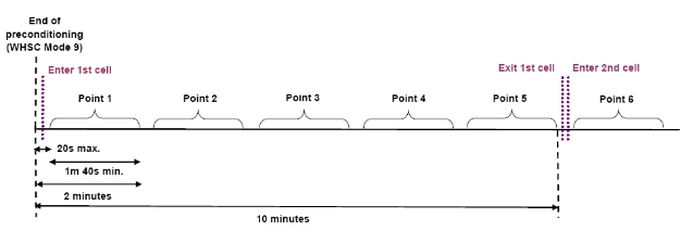
Figures 5 and 6
WNTE test cycle grids
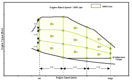
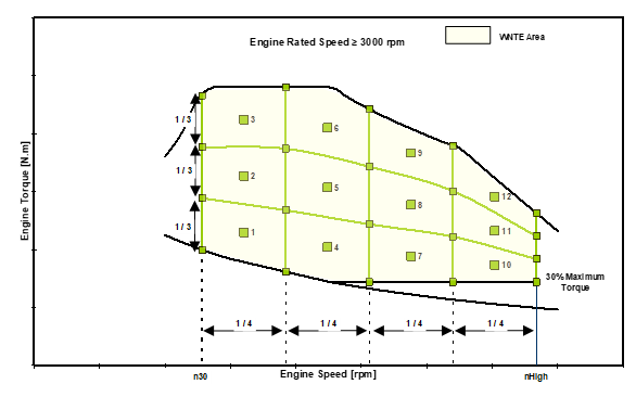
7.6. Rounding
Each final test result shall be rounded in one step to the number of places to the right of the decimal point indicated by the applicable WHDC emission standard plus one additional significant figure, in accordance with
ASTM E 29-06. No rounding of intermediate values leading to the final brake specific emission result is permitted.
8. Reserved
9. Reserved
10. Statement of off-cycle emission compliance
In the application for type approval, the manufacturer shall provide a statement that the engine family or vehicle complies with the requirements of this Regulation limiting off-cycle emissions. In addition to this statement, compliance with the applicable emission limits and in-use requirements shall be verified through additional tests.
10.1. Example statement of Off-Cycle Emission compliance
The following is an example compliance statement:
"(Name of manufacturer) attests that the engines within this engine family comply with all requirements of this annex. (Name of manufacturer) makes this statement in good faith, after having performed an appropriate engineering evaluation of the emissions performance of the engines within the engine family over the applicable range of operating and ambient conditions."
10.2. Basis for Off-Cycle Emission compliance statement
The manufacturer shall maintain records at the manufacturer's facility which contain all test data, engineering analyses, and other information which provides the basis for the OCE compliance statement. The manufacturer shall provide such information to the Certification or Type Type Approval Authority upon request.
11. Documentation
The Type Approval Authority shall require that the manufacturer provides a documentation package. This should describe any element of design and emission control strategy of the engine system and the means by which it controls its output variables, whether that control is direct or indirect.
The information shall include a full description of the emission control strategy. In addition, this shall include information on the operation of all AES and BES, including a description of the parameters that are modified by any AES and the boundary conditions under which the AES operate, and indication of which AES and BES are likely to be active under the conditions of the test procedures in this annex.
This information shall be made available in the "extended documentation package" according to the documentation requirements specified in paragraph 5.1.4.
The methodology for the assessment of AES is described in Appendix 2 to this annex.
Annex 10 - Appendix 2 Methodology for the assessment of AES
For the purposes of assessing the AES, the approval authority shall verify at least whether the requirement laid down in this Appendix are fulfilled.
1. The increase of emissions induced by the AES shall be kept at the lowest possible level:
(a) The increase of total emissions when using an AES shall be kept at the lowest possible level throughout the normal use and life of the vehicles;
(b) Whenever a technology or design that would allow for improved emission control is available on the market at the time of the AES preliminary assessment it shall be used with no unjustified modulation.
2. When used to justify an AES, the risk of sudden and irreparable damage to the engine, shall be appropriately demonstrated and documented, including the following information:
(a) Proof of catastrophic (i.e. sudden and irreparable) engine damage shall be provided by the manufacturer, along with a risk assessment which includes an evaluation of the likelihood of the risk occurring and severity of the possible consequences, including results of tests carried out to this effect;
(b) When a technology or design is available on the market at the time of the AES application that eliminates or reduces that risk, it shall be used to the largest extent technically possible (i.e. with no unjustified modulation);
(c) Durability and the long-term protection of the engine or components of the emission control system from wear and malfunctioning shall not be considered an acceptable reason to accept an AES.
3. An adequate technical description shall document why it is necessary to use an AES for the safe operation of the vehicle:
(a) Proof of an increased risk to the safe operation of the vehicle should be provided by the manufacturer along with a risk assessment which includes an evaluation of the likelihood of the risk occurring and severity of the possible consequences, including results of tests carried out to this effect;
(b) When a different technology or design is available on the market at the time of the AES application that would allow for lowering the safety risk, it shall be used to the largest extent technically possible (i.e. with no unjustified modulation).
4. An adequate technical description shall document why it is necessary to use an AES during engine start or warm up:
(a) Proof of the need to use an AES during engine start shall be provided by the manufacturer along with a risk assessment which includes an evaluation of the likelihood of the risk occurring and severity of the possible consequences, including results of tests carried out to this effect;
(b) Where a different technology or design is available on the market at the time of the AES application that would allow for improved emission control upon engine start, it shall be used to the largest extent technically possible.
Annex 11 Requirements to ensure the correct operation of NOx control measures
1. Introduction
This annex sets out the requirements to ensure the correct operation of NOx control measures. It includes requirements for vehicles that rely on the use of a reagent in order to reduce emissions.
2. General requirements
Any engine system falling within the scope of this annex shall be designed, constructed and installed so as to be capable of meeting these requirements throughout the normal life of the engine under normal conditions of use. In achieving this objective it is acceptable that engines which have been used in excess of the appropriate durability period referred to in paragraph 5.4. of this Regulation may show some deterioration in performance and sensitivity of the monitoring system.
2.1. Alternative approval
2.1.1. If requested by the manufacturer, for vehicles of categories M2 and N1, for vehicles of categories M1 and N2 with a technically permissible maximum laden mass not exceeding 7.5 tonnes, and for vehicles of category M3 Class I, Class II and Classes A and Class with a permissible mass not exceeding 7.5 tonnes, compliance with the requirements of Annex 6 to the 07 series of amendments to Regulation No. 83 shall be considered equivalent to the compliance with this annex.
2.1.2. If the alternative approval is used:
2.1.2.1. The information related to the correct operation of NOx control measures in paragraphs 3.2.12.2.8.1. to 3.2.12.2.8.5. of Part 2 of Annex 1 to this Regulation is replaced by the information of paragraph 3.2.12.2.8. of Annex 1 to the 07 series of amendments to Regulation No. 83.
2.1.2.2. The following exceptions shall apply regarding the application of the requirements set out in Appendix 6 to the 07 series of amendments to Regulation No. 83 and those of this Annex:
2.1.2.2.1. The provisions on reagent quality monitoring set out in paragraphs 7.1. to 7.1.2. of this Annex shall apply, instead of paragraphs 4.1. and 4.2. of Appendix 6 to the 07 series of amendments to Regulation No. 83.
2.1.2.2.2. The provisions on dosing activity monitoring set out in paragraph 8.4. of this Annex shall apply, instead of paragraph 5. of Appendix 6 to the 07 series of amendments to Regulation No. 83.
2.1.2.2.3. The driver warning system referred to in paragraph 4., 7. and 8. of this Annex shall be understood as the driver warning system in paragraph 3. of Appendix 6 to the 07 series of amendments to Regulation No. 83.
2.1.2.2.4. Paragraph 6 of Appendix 6 to the 07 series of amendments to Regulation No. 83 shall not apply.
2.1.2.2.5. The provisions set out in paragraph 5.2. of this annex shall apply in the case of vehicles for use by the rescue services or to vehicles designed and constructed for use by the armed services, civil defence, fire services and forces responsible for maintaining public order.
2.2. Required information
2.2.1. Information that fully describes the functional operational characteristics of an engine system covered by this annex shall be provided by the manufacturer in the form set out in Annex 1.
2.2.2. In its application for type approval, the manufacturer shall specify the characteristics of all reagents consumed by any emission control system. This specification shall include types and concentrations, operational temperature conditions, and references to international standards.
2.2.3. Detailed written information fully describing the functional operation characteristics of the driver warning system as provided in accordance with paragraph 4. and of the driver inducement system as provided in accordance with paragraph 5. shall be submitted to the Type Approval Authority at the time of application for the type approval.
2.2.4. When a manufacturer applies for an approval of an engine or engine family as a separate technical unit, it shall include in the documentation package referred to in paragraphs 3.1.3., 3.2.3. or 3.3.3. of this Regulation the appropriate requirements that will ensure that the vehicle, when used on the road or elsewhere as appropriate, will comply with the requirements of this annex. This documentation shall include the following:
(a) The detailed technical requirements including the provisions ensuring the compatibility with the monitoring, warning, and inducement systems present in the engine system for the purpose of complying with the requirements of this annex;
(b) The verification procedure to be complied with for installation of the engine in the vehicle.
The existence and the adequacy of such installation requirements may be checked during the approval process of the engine system.
The documentation referred to in points (a) and (b) above shall not be required if the manufacturer applies for a type approval of a vehicle with regard to emissions.
2.3. Operating conditions
2.3.1. Any engine system falling within the scope of this annex shall retain its emission control function during all conditions regularly pertaining within the territory of the relevant region (e.g. European Union), especially at low ambient temperatures, in line with Annex 10.
2.3.2. The emission control monitoring system shall be operational:
(a) At ambient temperatures between 266 K and 308 K (-7 °C and 35 °C);
(b) At all altitudes below 1,600 m;
(c) At engine coolant temperatures above 343 K (70 °C).
This paragraph shall not apply in the case of monitoring for reagent level in the storage tank, where monitoring shall be conducted under all conditions where measurement is technically feasible including all conditions when a liquid reagent is not frozen.
2.4. Reagent freeze protection
2.4.1. The manufacturer may use a heated or a non-heated reagent tank and dosing system, in accordance with the general requirements of paragraph 2.3.1. A heated system shall meet the requirements of paragraph 2.4.2. A non heated system shall meet the requirements of paragraph 2.4.3.
2.4.1.1. The use of a non-heated reagent tank and dosing system shall be indicated in written instructions to the owner of the vehicle.
2.4.2. Heated reagent tank and dosing system
2.4.2.1. If the reagent has frozen, the manufacturer shall ensure that reagent is available for use within a maximum of 70 minutes after the start of the vehicle at 266 K (- 7 °C) ambient temperature.
2.4.2.2. Demonstration
2.4.2.2.1. The reagent tank and dosing system shall be soaked at 255 K (-18 °C) for 72 hours or until the bulk of the reagent becomes solid.
2.4.2.2.2. After the soak period provided in paragraph 2.4.2.2.1. the engine shall be started and operated at 266 K (- 7 °C) ambient temperature as follows: 10 to 20 minutes idling, followed by up to 50 minutes at no more than 40 per cent load.
2.4.2.2.3. The reagent dosing system shall be fully functional at the end of the test procedures described in paragraphs 2.4.2.2.1. and 2.4.2.2.2.
2.4.2.2.4. Demonstration of compliance with the requirements of paragraph 2.4.2.2. may be done in a cold chamber test cell equipped with an engine or vehicle dynamometer or may be based on vehicle field tests, as approved by the Type Approval Authority.
2.4.3. Non-heated reagent tank and dosing system
2.4.3.1. The driver warning system described in paragraph 4. shall be activated if no reagent dosing occurs at an ambient temperature ≤ 266 K (-7 °C).
2.4.3.2. The severe inducement system described in paragraph 5.4. shall be activated if no reagent dosing occurs at an ambient temperature ≤ 266 K (-7 °C) within a maximum of 70 minutes after vehicle start.
2.5. Each separate reagent tank installed on a vehicle shall include a means for taking a sample of any fluid inside the tank and for doing so without the need for information not stored on-board the vehicle. The sampling point shall be easily accessible without the use of any specialised tool or device. Keys or systems which are normally carried on the vehicle for locking access to the tank shall not be considered to be specialised tools or devices for the purpose of this paragraph.
3. Maintenance requirements
3.1. The manufacturer shall furnish or cause to be furnished to all owners of new vehicles or new engines type-approved in accordance with this Regulation written instructions about the emission control system and its correct operation.
Those instructions shall state that if the vehicle emission control system is not functioning correctly the driver will be informed of a problem by the driver warning system, and that operation of the driver inducement system as a consequence of ignoring this warning will result in the vehicle being unable to efficiently conduct its mission.
3.2. The instructions shall indicate requirements for the proper use and maintenance of vehicles in order to maintain their emissions performance, including, where relevant, the proper use of consumable reagents.
3.3. The instructions shall be written in clear and non-technical language and in the official language or languages of the Member State in which a new vehicle or engine is sold or registered.
3.4. The instructions shall specify if consumable reagents have to be refilled by the vehicle operator between normal maintenance intervals. The instructions shall also specify the required reagent quality. They shall indicate how the operator should refill the reagent tank. The information shall also indicate a likely rate of reagent consumption for the type of vehicle and how often it is likely to need to be replenished.
3.5. The instructions shall specify that use of, and refilling with, a required reagent of the correct specifications is essential in order for the vehicle to comply with the requirements for the issuing of the certificate of conformity for that vehicle type.
3.6. The instructions shall state that it may be a criminal offence to use a vehicle that does not consume any reagent if the reagent is required for the reduction of emissions.
3.7. The instructions shall explain how the warning system and driver inducement systems work. In addition, the consequences, in terms of vehicle performance and fault logging, of ignoring the warning system and not replenishing the reagent or rectifying a problem shall be explained.
4. Driver warning system
4.1. The vehicle shall include a driver warning system using visual alarms that informs the driver when a low reagent level, incorrect reagent quality, too low a rate of reagent consumption, or a malfunction, has been detected that may be due to tampering and that will lead to operation of the driver inducement system if not rectified in a timely manner. The warning system shall also be active when the driver inducement system described in paragraph 5. has been activated.
4.2. The vehicle On-Board Diagnostics (OBD) display system described in Annex 9B shall not be used for the purpose of providing the visual alarms described in paragraph 4.1. The warning shall not be the same as the warning used for the purposes of OBD (that is, the MI – malfunction indicator) or other engine maintenance. It shall not be possible to turn off the warning system or visual alarms by means of a scan-tool if the cause of the warning activation has not been rectified. Conditions for activation and deactivation of the warning system and visual alarms are described in Appendix 2 to this annex.
4.3. The driver warning system may display short messages, including messages indicating clearly the following:
(a) The remaining distance or time before activation of the low-level or severe inducements;
(b) The level of torque reduction;
(c) The conditions under which vehicle disablement can be cleared.
The system used for displaying the messages referred to in this point may be the same as the one used for OBD or other maintenance purposes.
4.4. At the choice of the manufacturer, the warning system may include an audible component to alert the driver. The cancelling of audible warnings by the driver is permitted.
4.5. The driver warning system shall be activated as specified in paragraphs 6.2., 7.2., 8.4., and 9.3.
4.6. The driver warning system shall be deactivated when the conditions for its activation have ceased to exist. The driver warning system shall not be automatically deactivated without the reason for its activation having been remedied.
4.7. The warning system may be temporarily interrupted by other warning signals providing important safety-related messages.
4.8. A facility to permit the driver to dim the visual alarms provided by the warning system may be provided on vehicles for use by the rescue services or on vehicles designed and constructed for use by the armed services, civil defence, fire services and forces responsible for maintaining public order.
4.9. Details of the driver warning system activation and deactivation procedures are specified in Appendix 2 to this annex.
4.10. As part of the application for type approval under this Regulation, the manufacturer shall demonstrate the operation of the driver warning system, as specified in Appendix 1 to this annex.
5. Driver inducement system
5.1. The vehicle shall incorporate a two-stage driver inducement system starting with a low-level inducement (a performance restriction) followed by a severe inducement (effective disablement of vehicle operation).
5.2. The requirement for a driver inducement system shall not apply to engines or vehicles for use by the rescue services or to engines or on vehicles designed and constructed for use by the armed services, civil defence, fire services and forces responsible for maintaining public order. Permanent deactivation of the driver inducement system shall only be done by the engine or vehicle manufacturer.
5.3. Low-level inducement system
The low-level inducement system shall reduce the maximum available engine torque across the engine speed range by 25 per cent between the peak torque speed and the governor breakpoint as described in Appendix 3 to this annex. The maximum available reduced engine torque below the peak torque speed of the engine before imposition of the torque reduction shall not exceed the reduced torque at that speed.
The low-level inducement system shall be activated when the vehicle becomes stationary for the first time after the conditions specified in paragraphs 6.3., 7.3., 8.5. and 9.4. below, have occurred.
5.4. Severe inducement system
The vehicle or engine manufacturer shall incorporate at least one of the severe inducement systems described in paragraphs 5.4.1. to 5.4.3. and the "disable on time limit" system described in paragraph 5.4.4.
5.4.1. A "disable after restart" system shall limit the vehicle speed to 20 km/h ("creep mode") after the engine has been shut down at the request of the driver ("key-off").
5.4.2. A "disable after fuelling" system shall limit the vehicle speed to 20 km/h ("creep mode") after the fuel tank level has risen a measurable amount, which shall not be more than 10 per cent of the fuel tank capacity and shall be approved by the Type Approval Authority based on the technical capabilities of the fuel level meter and a declaration by the manufacturer.
5.4.3. A "disable after parking" system shall limit the vehicle speed to 20 km/h ("creep mode") after the vehicle has been stationary for more than one hour.
5.4.4. A "disable on time limit" system shall limit the vehicle speed to 20 km/h ("creep mode") on the first occasion when the vehicle becomes stationary2 after eight hours of engine operation if none of the systems described in paragraphs 5.4.1. to 5.4.3. above has been previously been activated.
5.5. The driver inducement system shall be enabled as specified in paragraphs 6.3., 7.3., 8.5., and 9.4.
5.5.1. When the driver inducement system has determined that the severe inducement system shall be activated, the low-level inducement system shall remain activated until the vehicle speed has been limited to 20 km/h ("creep mode").
5.6. The driver inducement system shall be deactivated when the conditions for its activation have ceased to exist. The driver inducement system shall not be automatically deactivated without the reason for its activation having been remedied.
5.7. Details of the driver inducement system activation and deactivation procedures are described in Appendix 2 to this annex.
5.8. As part of the application for type approval under this Regulation, the manufacturer shall demonstrate the operation of the driver inducement system, as specified in Appendix 1 to this annex.
6. Reagent availability
6.1. Reagent indicator
The vehicle shall include a specific indicator on the dashboard that clearly informs the driver of the level of reagent in the reagent storage tank. The minimum acceptable performance level for the reagent indicator is that it shall continuously indicate the reagent level whilst the driver warning system referred to in paragraph 4. is activated to indicate problems with reagent availability. The reagent indicator may be in the form of an analogue or digital display, and may show the level as a proportion of the full tank capacity, the amount of remaining reagent, or the estimated driving distance remaining.
The reagent indicator shall be placed in close proximity to the fuel level indicator.
6.2. Activation of the driver warning system
6.2.1. The driver warning system specified in paragraph 4. shall be activated when the level of reagent is less than 10 per cent of the capacity of the reagent tank or a higher percentage at the choice of the manufacturer.
6.2.2. The warning provided shall be sufficiently clear for the driver to understand that the reagent level is low. When the warning system includes a message display system, the visual warning shall display a message indicating a low level of reagent. (for example, "urea level low", "AdBlue level low", or "reagent low").
6.2.3. The driver warning system does not initially need to be continuously activated, however activation shall escalate in intensity so that it becomes continuous when the level of the reagent is approaching a very low proportion of the capacity of the reagent tank and the point where the driver inducement system will come into effect is approached. It shall culminate in a driver notification at a level that is at the choice of the manufacturer, but is sufficiently more noticeable than the point where the driver inducement system in paragraph 6.3. comes into effect.
6.2.4. The continuous warning shall not be easily disabled or ignored. When the warning system includes a message display system, an explicit message shall be displayed (for example. "fill up urea", "fill up AdBlue", or "fill up reagent"). The continuous warning may be temporarily interrupted by other warning signals providing important safety related messages.
6.2.5. It shall not be possible to turn off the driver warning system until the reagent has been replenished to a level not requiring its activation.
6.3. Activation of the driver inducement system
6.3.1. The low-level inducement system described in paragraph 5.3. shall be enabled, and subsequently activated according to the requirements of that section, if the reagent tank level goes below 2.5 per cent of its nominally full capacity or a higher percentage at the choice of the manufacturer.
6.3.2. The severe inducement system described in paragraph 5.4. shall be enabled, and subsequently activated according to the requirements of that section, if the reagent tank is empty (that is, the dosing system is unable to draw further reagent from the tank) or at any level below 2.5 per cent of its nominally full capacity at the discretion of the manufacturer.
6.3.3. It shall not be possible to turn off the low-level or severe driver inducement system until the reagent has been replenished to a level not requiring their respective activation.
7. Reagent quality monitoring
7.1. The vehicle shall include a means of determining the presence of an incorrect reagent on board a vehicle.
7.1.1. The manufacturer shall specify a value CDmin, which is greater than the highest reagent concentration that results in tailpipe emissions exceeding the limit values specified in paragraph 5.3. of this Regulation.
7.1.1.1. During the phase-in period specified in paragraph 4.10.7. of this Regulation and upon request of the manufacturer for the purpose of paragraph 7.1.1. the reference to the NOx emission limit specified in paragraph 5.3. to this Regulation shall be replaced by the value of 900 mg/kWh.
7.1.1.2. The value of CDmin shall be demonstrated during type approval by the procedure defined in Appendix 6 to this annex and recorded in the extended documentation package as specified in paragraph 5.1.4. to this Regulation.
7.1.2. Any reagent concentration lower than CDmin shall be detected and be regarded, for the purpose of paragraph 7.1., as being incorrect reagent.
7.1.3. A specific counter ("the reagent quality counter") shall be attributed to the reagent quality. The reagent quality counter shall count the number of engine operating hours with an incorrect reagent.
7.1.4. Details of the reagent quality counter activation and deactivation criteria and mechanisms are described in Appendix 2 to this annex.
7.1.5. The reagent quality counter information shall be made available in a standardised manner in accordance with the provisions of Appendix 5 to this annex.
7.2. Activation of the driver warning system
When the monitoring systems detects or, as appropriate, confirms that the reagent quality is incorrect, the driver warning system described in paragraph 4. shall be activated. When the warning system includes a message display system, it shall display a message indicating the reason for the warning (for example: "incorrect urea detected", "incorrect AdBlue detected", or "incorrect reagent detected").
7.3. Activation of the driver inducement system
7.3.1. The low-level inducement system described in paragraph 5.3. shall be enabled, and subsequently activated according to the requirements of that section, if the reagent quality is not rectified within 10 engine operating hours after the activation of the driver warning system described in paragraph 7.2.
7.3.2. The severe inducement system described in paragraph 5.4. shall be enabled, and subsequently activated according to the requirements of that section, if the reagent quality is not rectified within 20 engine operating hours after the activation of the driver warning system described in paragraph 7.2.
7.3.3. The number of hours prior to activation of the inducement systems shall be reduced in case of a repetitive occurrence of the malfunction, in accordance with the mechanism described in Appendix 2 to this annex.
8. Reagent consumption and dosing activity monitoring
8.1. The vehicle shall include means of determining reagent consumption, interruption of the reagent dosing activity and providing off-board access to consumption information.
8.2. Reagent consumption and dosing activity counters
8.2.1. A specific counter shall be attributed to the reagent consumption (the "reagent consumption counter") and another to the dosing activity (the "dosing activity counter"). These counters shall count the number of engine operating hours which occur with an incorrect reagent consumption and, respectively, an interruption of the reagent dosing activity.
8.2.2. Details of the reagent consumption counter and dosing counter activation and deactivation criteria and mechanisms are described in Appendix 2 to this annex.
8.2.3. The reagent consumption counter and the dosing counter information shall be made available in a standardised manner according to the provisions of Appendix 5 to this annex.
8.3. Monitoring conditions
8.3.1. The maximum detection period for insufficient reagent consumption is five hours or the period equivalent to a demanded reagent consumption of at least 2 litres, whichever is longer.
8.3.1.1. When the reagent consumption is monitored by using at least one of the following parameters:
(a) The level of reagent in the on-vehicle storage tank, or
(b) The flow of reagent or quantity of reagent injected at a position as close as technically possible to the point of injection into an exhaust after-treatment system,
The maximum detection period for insufficient reagent consumption is extended to 48 hours or to the period equivalent to a demanded reagent consumption of at least 15 litres, whichever is longer.
8.3.2. In order to monitor reagent consumption, at least one of the following parameters within the vehicle or engine shall be monitored:
(a) The level of reagent in the on-vehicle storage tank;
(b) The flow of reagent or quantity of reagent injected at a position as close as technically possible to the point of injection into an exhaust after-treatment system.
8.4. Activation of the driver warning system
8.4.1. The driver warning system described in paragraph 4. shall be activated if a deviation of more than fifty per cent between the average reagent consumption and the average demanded reagent consumption by the engine system over a period to be defined by the manufacturer, which shall not be longer than the maximum period defined in paragraph 8.3.1., or, when applicable, paragraph 8.3.1.1., is detected. When the warning system includes a message display system, it shall display a message indicating the reason for the warning (for example: "urea dosing malfunction", "AdBlue dosing malfunction", or "reagent dosing malfunction").
8.4.2. The driver warning system described in paragraph 4. shall be activated in the case of interruption in reagent dosing. When the warning system includes a message display system, it shall display a message indicating an appropriate warning. This activation shall not be required where the interruption is demanded by the engine ECU because the vehicle operating conditions are such that the vehicle’s emission performance does not require reagent dosing.
8.5. Activation of the driver inducement system
8.5.1. The low-level inducement system described in paragraph 5.3. shall be enabled, and subsequently activated according to the requirements of that section, if an error in the reagent consumption or an interruption in reagent dosing is not rectified within 10 engine operating hours after the activation of the driver warning system specified in paragraphs 8.4.1. and 8.4.2.
8.5.2. The severe inducement system described in paragraph 5.4. shall be enabled, and subsequently activated according to the requirements of that section, if an error in the reagent consumption or an interruption in reagent dosing is not rectified within 20 engine operating hours after the activation of the driver warning system in paragraphs 8.4.1. and 8.4.2.
8.5.3. The number of hours prior to activation of the inducement systems shall be reduced in case of a repetitive occurrence of the malfunction in accordance with the mechanism described in Appendix 2 to this annex.
9. Monitoring failures that may be attributed to tampering
9.1. In addition to the level of reagent in the reagent tank, the reagent quality, and the reagent consumption, the following failures shall be monitored by the anti-tampering system because they may be attributed to tampering:
(a) Impeding of the EGR valve operation;
(b) Failures of the anti-tampering monitoring system, as described in paragraph 9.2.1.
9.2. Monitoring requirements
9.2.1. The anti-tampering monitoring system shall be monitored for electrical failures and for removal or deactivation of any sensor that prevents it from diagnosing any other failures mentioned in paragraphs 6. to 8. (component monitoring).
A non-exhaustive list of sensors that affect the diagnostic capability are those directly measuring NOx concentration, urea quality sensors, ambient sensors, and sensors used for monitoring reagent dosing activity, reagent level, or reagent consumption.
9.2.2. EGR valve counter
9.2.2.1. A specific counter shall be attributed to an impeded EGR valve. The EGR valve counter shall count the number of engine operating hours when any DTC associated with an impeded EGR valve is confirmed to be active.
9.2.2.2. Details of the EGR valve counter activation and deactivation criteria and mechanisms are described in Appendix 2 to this annex.
9.2.2.3. The EGR valve counter information shall be made available in a standardised manner in accordance with the provisions of Appendix 5 to this annex.
9.2.3. Monitoring system counters
9.2.3.1. A specific counter shall be attributed to each of the monitoring failures considered in point (b) of paragraph 9.1. The monitoring system counters shall count the number of engine operating hours when the DTC associated with a malfunction of the monitoring system is confirmed to be active. Grouping of several faults into a single counter is permitted.
9.2.3.2. Details of the criteria for activation and deactivation of the monitoring system counters and the associated mechanisms are described in Appendix 2 to this annex.
9.2.3.3. The monitoring system counter information shall be made available in a standardised manner in accordance with the provisions of Appendix 5 to this annex.
9.3. Activation of the driver warning system
The driver warning system described in paragraph 4. shall be activated in the case where any of the failures specified in paragraph 9.1. occurs, and shall indicate that an urgent repair is required. When the warning system includes a message display system, it shall display a message indicating either the reason for the warning (for example, "reagent dosing valve disconnected", or "critical emission failure").
9.4. Activation of the driver inducement system
9.4.1. The low-level inducement system described in paragraph 5.3. shall be enabled, and subsequently activated according to the requirements of that section, if a failure specified in paragraph 9.1. is not rectified within 36 engine operating hours after the activation of the driver warning system in paragraph 9.3.
9.4.2. The severe inducement system described in paragraph 5.4. shall be enabled, and subsequently activated according to the requirements of that section, if a failure specified in paragraph 9.1. is not rectified within 100 engine operating hours after the activation of the driver warning system in paragraph 9.3.
9.4.3. The number of hours prior to activation of the inducement systems shall be reduced in case of a repetitive occurrence of the malfunction in accordance with the mechanism described in Appendix 2 to this annex.
Annex 11 ‑ Appendix 1 Demonstration requirements
A.1.1. General
A.1.1.1 The manufacturer shall submit to the Type Approval Authority a complete documentation package justifying the compliance of the SCR system with the requirements of this annex as regards its capabilities for monitoring and activation of the driver warning and inducement system, which may include:
(a) Algorithms and decision charts;
(b) Tests and/or simulation results;
(c) Reference to previously approved monitoring systems, etc.
A.1.1.2. Compliance with the requirements of this annex shall be demonstrated during type approval by performing, as illustrated in Table 1 and specified in this Appendix, the following demonstrations:
(a) A demonstration of the warning system activation;
(b) A demonstration of the low level inducement system activation;
(c) A demonstration of the severe inducement system activation.
Table 1
Illustration of the content of the demonstration process in accordance with the provisions in paragraphs A.1.3., A.1.4. and A.1.5.
| Demonstration elements |
Warning system activation specified in paragraph A.1.3. | (a) 4 activation tests (incl. lack of reagent) (b) Supplementary demonstration elements, as appropriate |
Low-level inducement activation specified in paragraph A.1.4. | (a) 2 activation tests (incl. lack of reagent) (b) Supplementary demonstration elements (c ) 1 torque reduction test |
Severe inducement activation specified in paragraph A.1.5. | (a) 2 activation tests (incl. lack of reagent) (b) Supplementary demonstration elements, as appropriate (c) Demonstration elements of correct vehicle behavior during inducement |
A.1.2. Engine families or OBD engine families
The compliance of an engine family or an OBD engine family with the requirements of this annex may be demonstrated by testing one of the members of the family under consideration, provided that the manufacturer demonstrates to the Type Approval Authority that the monitoring systems necessary for complying with the requirements of this annex are similar within the family.
A.1.2.1. This demonstration may be performed by presenting to the approval authorities such elements as algorithms, functional analyses, etc.
A.1.2.2. The test engine is selected by the manufacturer in agreement with the Type Approval Authority. It may or may not be the parent engine of the considered family.
A.1.2.3. In the case where engines of an engine family belong to an OBD engine family that has already been type-approved, the compliance of that engine family is deemed to be demonstrated without further testing (Figure 1), provided the manufacturer demonstrates to the authority that the monitoring systems necessary for complying with the requirements of this annex are similar within the engine and OBD engine families under consideration.
Figure 1
Previously demonstrated conformity of an OBD engine family

A.1.3. Demonstration of the warning system activation
A.1.3.1. The compliance of the warning system activation shall be demonstrated by performing one test for each of the failure categories considered in paragraphs 6. to 9. of this annex such as: lack of reagent, low reagent quality, low reagent consumption, failure of components of the monitoring system.
A.1.3.2. Selection of the failures to be tested
A.1.3.2.1. For the purpose of demonstrating the activation of the warning system in case of a wrong reagent quality, a reagent shall be selected with a concentration of the active ingredient equal to or higher than the minimum acceptable reagent concentration CDmin, communicated by the manufacturer in accordance with the requirements of paragraph 7.1.1. of this annex.
A.1.3.2.2. For the purpose of demonstrating the activation of the warning system in the case of an incorrect rate of reagent consumption, it shall be sufficient to arrange an interruption of the dosing activity.
A.1.3.2.2.1. Where activation of the warning system has been demonstrated by interruption of the dosing activity, the manufacturer shall, in addition, present the Type Approval Authority with evidence such as algorithms, functional analyses, the results of previous tests, etc. to show that the warning system will activate correctly in the case of an incorrect rate of reagent consumption due to other causes.
A.1.3.2.3. For the purpose of demonstrating the activation of the warning system in case of failures that may be attributed to tampering, as defined in paragraph 9. of this annex, the selection shall be performed in accordance with the following requirements:
A.1.3.2.3.1. The manufacturer shall provide the Type Approval Authority with a list of such potential failures.
A.1.3.2.3.2. The failure to be considered in the test shall be selected by the Type Approval Authority from this list referred to in paragraph A.1.3.2.3.1.
A.1.3.3. Demonstration
A.1.3.3.1. For the purposes of this demonstration of the activation of the warning system a separate test shall be performed for each of the failures considered in paragraph A.1.3.1.
A.1.3.3.2. During a test, no failure shall be present other than the one addressed by the test.
A.1.3.3.3. Prior to starting a test, all DTC shall have been erased.
A.1.3.3.4. At the request of the manufacturer, and with the agreement of the Type Approval Authority, the failures subject to testing may be simulated.
A.1.3.3.5. For failures other than lack of reagent, once the failure has been induced or simulated, the detection of that failure shall be performed in accordance with paragraph 7.1.2.2. of Annex 9B.
A.1.3.3.5.1. The detection sequence shall be stopped once the DTC of the selected failure has got the "confirmed and active" status.
A.1.3.3.6. For the purpose of demonstrating the activation of the warning system in case of lack of reagent availability, the engine system shall be operated over one or more operating sequences at the discretion of the manufacturer.
A.1.3.3.6.1. The demonstration shall start with a level of reagent in the tank to be agreed between the manufacturer and the Type Approval Authority but representing not less than 10 per cent of the nominal capacity of the tank.
A.1.3.3.6.2. The warning system is deemed to have performed in the correct manner if the following conditions are met simultaneously:
(a) The warning system has been activated with a reagent availability greater or equal to 10 per cent of the capacity of the reagent tank;
(b) The "continuous" warning system has been activated with a reagent availability greater or equal to the value declared by the manufacturer according to the provisions of paragraph 6. of this annex.
A.1.3.4. The demonstration of the warning system activation is deemed to be accomplished for reagent level events if, at the end of each demonstration test performed according to paragraph A.1.3.2.1., the warning system has been properly activated.
A.1.3.5. The demonstration of the warning system activation is deemed to be accomplished for DTC triggered events if, at the end of each demonstration test performed according to paragraph A.1.3.2.1., the warning system has been properly activated and the DTC for the selected failure has got the status shown in Table 1 in Appendix 2 to this annex.
A.1.4. Demonstration of the inducement system
A.1.4.1. The demonstration of the inducement system shall be done by tests performed on an engine test bench.
A.1.4.1.1. Any additional vehicle components or sub-systems, such as ambient temperature sensors, level sensors, and driver warning and information systems, that are required in order to perform the demonstrations shall be connected to the engine system for that purpose, or shall be simulated, to the satisfaction of the Type Approval Authority.
A.1.4.1.2. If the manufacturer chooses, and subject to the agreement of the Type Approval Authority, the demonstration tests may be performed on a complete vehicle either by mounting the vehicle on a suitable test bed or by running it on a test track under controlled conditions.
A.1.4.2. The test sequence shall demonstrate the activation of the inducement system in case of lack of reagent and in case of one of the failures defined in paragraphs 7., 8., or 9. of this annex.
A.1.4.3. For the purpose of this demonstration,
(a) The Type Approval Authority shall select, in addition to the lack of reagent, one of the failures defined in paragraphs 7., 8. or 9. of this annex that has been previously used in the demonstration of the warning system;
(b) The manufacturer shall be permitted to simulate, in agreement with the Type Approval Authority, the achievement of a certain number of operating hours;
(c) The achievement of the torque reduction required for low-inducement may be demonstrated at the same time as the general engine performance approval process performed in accordance with this Regulation. Separate torque measurement during the inducement system demonstration is not required in this case. The speed limitation required for severe inducement shall be demonstrated in accordance with the requirements of paragraph 5. of this annex.
A.1.4.4. The manufacturer shall, in addition, demonstrate the operation of the inducement system under those failure conditions defined in paragraphs 7., 8. or 9. of this annex which have not been chosen for use in demonstration tests described in paragraphs A.1.4.1., A.1.4.2. and A.1.4.3. These additional demonstrations may be performed by presentation to the Type Approval Authority of a technical case using evidence such as algorithms, functional analyses, and the results of previous tests.
A.1.4.4.1. These additional demonstrations shall, in particular, demonstrate to the satisfaction of the Type Approval Authority the inclusion of the correct torque reduction mechanism in the engine ECU.
A.1.4.5. Demonstration test of the low level inducement system
A.1.4.5.1. This demonstration starts when the warning system, or when appropriate "continuous" warning system, has been activated as a result of the detection of a failure selected by the Type Approval Authority.
A.1.4.5.2. When the system is being checked for its reaction to the case of lack of reagent in the tank, the engine system shall be run until the reagent availability has reached a value of 2.5 per cent of the nominal full capacity of the tank or the value declared by the manufacturer in accordance with paragraph 6.3.1. of this annex at which the low-level inducement system is intended to operate.
A.1.4.5.2.1. The manufacturer may, with the agreement of the Type Approval Authority, simulate continuous running by extracting reagent from the tank, either whilst the engine is running or whilst it is stopped.
A.1.4.5.3. When the system is checked for its reaction in the case of a failure other than a lack of reagent in the tank, the engine system shall be run for the relevant number of operating hours indicated in Table 2 of Appendix 2 or, at the choice of the manufacturer, until the relevant counter has reached the value at which the low-level inducement system is activated.
A.1.4.5.4. The demonstration of the low level inducement system shall be deemed to be accomplished if, at the end of each demonstration test performed in accordance with paragraphs A.1.4.5.2. and A.1.4.5.3., the manufacturer has demonstrated to the Type Approval Authority that the engine ECU has activated the torque reduction mechanism.
A.1.4.6. Demonstration test of the severe inducement system
A.1.4.6.1. This demonstration shall start from a condition where the low-level inducement system has been previously activated, and may be performed as a continuation of the tests undertaken to demonstrate the low-level inducement system.
A.1.4.6.2. When the system is checked for its reaction in the case of lack of reagent in the tank, the engine system shall be run until the reagent tank is empty (that is, until the dosing system cannot draw further reagent from the tank), or has reached the level below 2.5 per cent of nominal full capacity of the tank at which the manufacturer has declared that the severe inducement system will be activated.
A.1.4.6.2.1. The manufacturer may, with the agreement of the Type Approval Authority, simulate continuous running by extracting reagent from the tank, either whilst the engine is running or whilst it is stopped.
A.1.4.6.3. When the system is checked for its reaction in the case of a failure that is not a lack of reagent in the tank, the engine system shall then be run for the relevant number of operating hours indicated in Table 2 of Appendix 2 or, at the choice of the manufacturer, until the relevant counter has reached the value at which the severe inducement system is activated.
A.1.4.6.4. The demonstration of the severe inducement system shall be deemed to be accomplished if, at the end of each demonstration test performed in accordance with paragraphs A.1.4.6.2. and A.1.4.6.3. the manufacturer has demonstrated to the Type Approval Authority that the required vehicle speed limitation mechanism has been activated.
A.1.5. Demonstration of the vehicle speed limitation following activation of the severe inducement system
A.1.5.1. The demonstration of the vehicle speed limitation following activation of the severe inducement system shall be performed by the presentation to the Type Approval Authority of a technical case using evidence such as algorithms, functional analyses, and the result of previous tests.
A.1.5.1.1. Alternatively, if the manufacturer chooses, and subject to the agreement of the Type Approval Authority, the demonstration of vehicle speed limitation may be performed on a complete vehicle in accordance with the requirements of paragraph A.1.5.4., either by mounting the vehicle on a suitable test bed or by running it on a test track under controlled conditions.
A.1.5.2. When the manufacturer applies for an approval of an engine or engine family as a separate technical unit, the manufacturer shall provide the Type Approval Authority with evidence that the installation documentation package complies with the provisions of paragraph 2.2.4. of this annex concerning the measures to ensure that the vehicle, when used on the road or elsewhere as appropriate, will comply with the requirements of this annex regarding severe inducement.
A.1.5.3. If the Type Approval Authority is not satisfied with the evidence of proper operation of the severe inducement system that is provided by the manufacturer, the Type Approval Authority may request a demonstration on a single representative vehicle in order to confirm proper operation of the system. The vehicle demonstration shall be performed in accordance with the requirements of paragraph A.1.5.4.
A.1.5.4. Additional demonstration for confirming the effect of activation of the severe inducement system on a vehicle
A.1.5.4.1. This demonstration shall be performed at the request of the Type Approval Authority when it is not satisfied with the evidence of proper operation of the severe inducement system provided by the manufacturer. This demonstration shall be performed at the earliest opportunity in agreement with the Type Approval Authority.
A.1.5.4.2. One of the failures defined in paragraphs 6. to 9. of this annex shall be selected by the manufacturer, and shall be introduced or simulated on the engine system, as the manufacturer and the Type Approval Authority agree.
A.1.5.4.3. The inducement system shall be brought by the manufacturer to a state where the low-level inducement system has been activated and the severe inducement system has not yet been activated.
A.1.5.4.4. The vehicle shall be operated until the counter associated with the selected failure has reached the relevant number of operating hours indicated in Table 2 of Appendix 2 or, as appropriate, until either the reagent tank is empty or, has reached the level below 2.5 per cent of nominal full capacity of the tank at which the manufacturer has chosen to activate the severe inducement system.
A.1.5.4.5. If the manufacturer has opted for the "disable after restart" approach referred to in paragraph 5.4.1. of this annex, the vehicle shall be operated until the end of the current operating sequence, which must include a demonstration that the vehicle is capable of exceeding 20 km/h. After restart, the vehicle speed shall be limited to no more than 20 km/h.
A.1.5.4.6. If the manufacturer has opted for the "disable after fuelling" approach referred to in paragraph 5.4.2. of this annex, the vehicle shall be operated for a short distance, chosen by the manufacturer, after it has been brought to a state where there is sufficient spare capacity in the tank to permit it to be refuelled with the amount of fuel defined in paragraph 5.4.2. of this annex. The vehicle operation before refuelling shall include a demonstration that the vehicle is capable of exceeding 20 km/h. After re-fuelling the vehicle with the amount of fuel defined in paragraph 5.4.2. of this annex, the vehicle speed shall be limited to no more than 20 km/h.
A.1.5.4.7. If the manufacturer has opted for the "disable after parking" approach referred to in paragraph 5.4.3. of this annex, the vehicle shall be stopped after having been run for a short distance, chosen by the manufacturer, which is sufficient to demonstrate that the vehicle is capable of exceeding a speed of 20 km/h. After the vehicle has been stationary for more than one hour, the vehicle speed shall be limited to no more than 20 km/h.
Annex 11 ‑ Appendix 2 Description of the driver warning and inducement activation and deactivation mechanisms
A.2.1. To complement the requirements specified in this annex concerning the driver warning and inducement activation and deactivation mechanisms, this Appendix specifies the technical requirements for an implementation of those activation and deactivation mechanisms consistent with the OBD provisions of Annex 9B.
All definitions used in Annex 9B are applicable to this appendix.
A.2.2. Activation and deactivation mechanisms of the driver warning system
A.2.2.1. The driver warning system shall be activated when the diagnostic trouble code (DTC) associated with a malfunction justifying its activation has the status defined in Table 1.
Table 1
Activation of the driver warning system
Failure type | DTC status for activation of the warning system |
Poor reagent quality | Confirmed and active |
Low reagent consumption | Potential (if detected after 10 hours), potential or confirmed and active otherwise |
Absence of dosing | Confirmed and active |
Impeded EGR valve | Confirmed and active |
Malfunction of the monitoring system | Confirmed and active |
A.2.2.1.1. If the counter associated with the relevant failure is not at zero, and is consequently indicating that the monitor has detected a situation where the malfunction may have occurred for a second or subsequent time, the driver warning system shall be activated when the DTC has the status "potential".
A.2.2.2. The driver warning system shall be deactivated when the diagnostic system concludes that the malfunction relevant to that warning is no longer present or when the information, including DTCs relative to the failures, justifying its activation is erased by a scan tool.
A.2.2.2.1. Erasing of failure information by means of a scan tool
A.2.2.2.1.1. Erasing of information, including DTCs relative to failures justifying the activation of a driver warning signal and of their associated data, by means of a scan tool shall be performed in accordance with Annex 9B.
A.2.2.2.1.2. The erasing of failure information shall only be possible under "engine-off" conditions.
A.2.2.2.1.3. When failure information, including DTCs, is erased, any counter associated with these failures and which is specified in this annex as one that must not be erased shall not be erased.
A.2.3. Activation and deactivation mechanism of the driver inducement system
A.2.3.1. The driver inducement system shall be activated when the warning system is active and the counter relevant to the type of malfunction justifying its activation has reached the value specified in Table 2.
A.2.3.2. The driver inducement system shall be deactivated when the system no longer detects a malfunction justifying its activation, or if the information, including the DTCs, relative to the failures justifying its activation has been erased by a scan tool or maintenance tool.
A.2.3.3. The driver warning and inducement systems shall be immediately activated or deactivated as appropriate in accordance with the provisions of paragraph 6. of this annex after assessment of the reagent quantity in the reagent tank. In that case, the activation or deactivation mechanisms shall not depend upon the status of any associated DTC.
A.2.4. Counter mechanism
A.2.4.1. General
A.2.4.1.1. To comply with the requirements of this annex, the system shall contain separate counters to record the number of hours during which the engine has been operated while the system has detected any of the following:
(a) An incorrect reagent quality;
(b) An incorrect reagent consumption;
(c) An interruption of reagent dosing activity;
(d) An impeded EGR valve;
(e) A failure of the monitoring system as defined of paragraph 9.1. (b) of this annex.
A.2.4.1.2. Each of these counters shall count up to the maximum value provided in a 2 byte counter with 1 hour resolution, and shall hold that value unless the conditions allowing the counter to be reset to zero are met.
A.2.4.1.3. A manufacturer may use a single or multiple monitoring system counters.
A single counter may accumulate the number of hours of 2 or more different malfunctions relevant to that type of counter.
A.2.4.1.3.1. When the manufacturer decides to use multiple monitoring system counters, the system shall be capable of assigning a specific monitoring system counter to each malfunction that is relevant, in accordance with this annex, to that type of counter.
A.2.4.2. Principle of counter mechanisms
A.2.4.2.1. Each of the counters shall operate as follows:
A.2.4.2.1.1. If starting from zero, the counter shall begin counting as soon as a malfunction relevant to that counter is detected and the corresponding diagnostic trouble code (DTC) has the status described in Table 1.
A.2.4.2.1.2. The counter shall halt and hold its current value if a single monitoring event occurs and the malfunction that originally activated the counter is no longer detected or if the failure has been erased by a scan tool or a maintenance tool.
A.2.4.2.1.2.1. If the counter stops counting when the severe inducement system is active, the counter shall be kept frozen at the value defined in Table 2.
A.2.4.2.1.2.2. In the case of a single monitoring system counter, that counter shall continue counting if a malfunction relevant to that counter has been detected and its corresponding Diagnostic trouble code (DTC) has the status "confirmed and active". It shall halt and hold the value specified in paragraph A.2.4.2.1.2., or A.2.4.2.1.2.1. as appropriate, if no malfunction that would justify the counter activation is detected or if all the failures relevant to that counter have been erased by a scan tool or a maintenance tool.
Table 2
Counters and inducement
| DTC status for first activation of the counter | Counter value for low-level inducement | Counter value for
severe inducement | Frozen value held by the counter during the period just after severe inducement |
Reagent quality counter | Confirmed and active | 10 hours | 20 hours | 18 hours |
Reagent consumption counter | Potential or confirmed and active
(see Table 1) | 10 hours | 20 hours | 18 hours |
Dosing counter | Confirmed and active | 10 hours | 20 hours | 18 hours |
EGR valve counter | Confirmed and active | 36 hours | 100 hours | 95 hours |
Monitoring system counter | Confirmed and active | 36 hours | 100 hours | 95 hours |
A.2.4.2.1.3. Once frozen, the counter shall be reset to zero when the monitors relevant to that counter have run at least once to completion of their monitoring cycle without having detected a malfunction and no malfunction relevant to that counter has been detected during 36 engine operating hours since the counter was last held (see Figure 1).
A.2.4.2.1.4. The counter shall continue counting from the point at which it had been held if a malfunction relevant to that counter is detected during a period when the counter is frozen (see Figure 1).
Figure 1
Reactivation and resetting to zero of a counter after a period when its value has been frozen

A.2.5. Illustration of the activation and deactivation and counter mechanisms
A.2.5.1. This paragraph illustrates the activation and deactivation and counter mechanisms for some typical cases. The figures and descriptions given in paragraphs A.2.4.2., A.2.4.3. and A.2.4.4. are provided solely for the purposes of illustration in this annex and should not be referenced as examples of either the requirements of this Regulation or as definitive statements of the processes involved. For simplification purposes, for example, the fact that the warning system will also be active when the inducement system is active has not been mentioned in the illustrations given.
A.2.5.2. Figure 2 illustrates the operation of the activation and deactivation mechanisms when monitoring the reagent availability for five cases:
(a) Use case 1: the driver continues operating the vehicle in spite of the warning until vehicle operation is disabled;
(b) Repair case 1 ("adequate" refilling): the driver refills the reagent tank so that a level above the 10 per cent threshold is reached. Warning and inducement are de-activated;
(c) Repair cases 2 and 3 ("inadequate" refilling): the warning system is activated. The level of warning depends on the amount of available reagent;
(d) Repair case 4 ("very inadequate" refilling): the low-level inducement is activated immediately.
Figure 2
Reagent availability

A.2.5.3. Figure 3 illustrates three cases of wrong urea quality:
(a) Use case 1: the driver continues operating the vehicle in spite of the warning until vehicle operation is disabled;
(b) Repair case 1 ("bad" or "dishonest" repair): after disablement of the vehicle, the driver changes the quality of the reagent, but, soon after, changes it again for a poor quality one. The inducement system is immediately reactivated and vehicle operation is disabled after 2 engine operating hours;
(c) Repair case 2 ("good" repair): after disablement of the vehicle, the driver rectifies the quality of the reagent. However, some time afterwards, he refills again with a poor quality reagent. The warning, inducement, and counting processes restart from zero.
Figure 3
Filling with poor reagent quality

A.2.5.4. Figure 4 illustrates three cases of failure of the urea dosing system. This figure also illustrates the process that applies in the case of the monitoring failures described in paragraph 9. of this annex:
(a) Use case 1: the driver continues operating the vehicle in spite of the warning until vehicle operation is disabled;
(b) Repair case 1 ("good" repair): after disablement of the vehicle, the driver repairs the dosing system. However, some time afterwards, the dosing system fails again. The warning, inducement, and counting processes restart from zero;
(c) Repair case 2 ("bad" repair): during the low-level inducement time (torque reduction), the driver repairs the dosing system. Soon after, however, the dosing system fails again. The low-level inducement system is immediately reactivated and the counter restarts from the value it had at the time of repair.
Figure 4
Failure of the reagent dosing system

Annex 11 ‑ Appendix 4 Demonstration of correct installation on a vehicle in the case of engines type-approved as a separate technical unit
This appendix applies when the vehicle manufacturer requests type approval of a vehicle with an approved engine with regard to emissions in accordance with this Regulation.
In this case, and in addition to the installation requirements of paragraph 6. of this Regulation, a demonstration of the correct installation is required. This demonstration shall be performed by the presentation to the Type Approval Authority of a technical case using evidence such as engineering drawings, functional analyses, and the results of previous tests.
Where appropriate, and if the manufacturer chooses, the evidence presented may include installations of systems or components on real or simulated vehicles, provided that the manufacturer can present evidence that the presented installation properly represents the standard that will be achieved in production.
The demonstration shall address the conformity of the following elements to the requirements of this annex:
(a) The installation on board the vehicle as regards its compatibility with the engine-system (hardware, software and communication);
(b) The warning and inducement systems (for example, pictograms, activation schemes, etc.);
(c) The reagent tank and the elements (for example, sensors) mounted on the vehicle for the purpose of complying with this annex.
Correct activation of the warning and inducement systems, and of the information storage and on-board and off-board communication systems, may be checked. No check of these systems shall require the dismounting of the engine system or components, nor shall it generate unnecessary testing burden by requiring processes such as changing of the urea quality or running of the vehicle or engine for long periods of time. In order to minimise the burden upon the vehicle manufacturer, electric disconnections and simulation of counters with high operating hours shall be selected as checks on these systems if possible.
Annex 11 ‑ Appendix 5 Access to "NOx control information"
A.5.1. This appendix describes the specifications permitting access to information required in order to check the status of the vehicle with regard to the correct operation of the NOx control system ("NOx control information").
A.5.2. Access methods
A.5.2.1. The "NOx control information" shall be provided only in accordance with the standard or standards used in association with the retrieval of engine system information from the OBD system.
A.5.2.2. Access to the "NOx control information" shall not be dependent on any access code or other device or method obtainable only from the manufacturer or the manufacturer’s suppliers. Interpretation of that information shall not require any specialised or unique decoding information, unless that information is publicly available.
A.5.2.3. It shall be possible to retrieve all "NOx control information" from the system using the access method that is used to retrieve OBD information in accordance with Annex 9A.
A.5.2.4. It shall be possible to retrieve all "NOx control information" from the system using the test equipment that is used to retrieve OBD information in accordance with Annex 9A.
A.5.2.5. The "NOx control information" shall be available through "read-only" access (that is, it shall not be possible to clear, reset, erase, or modify any of the data).
A.5.3. Information content
A.5.3.1. The "NOx control information" shall contain at least the following information:
(a) The VIN (vehicle identification number);
(b) The status of the warning system (active; non-active);
(c) The status of the low-level inducement system (active; enabled; non-active);
(d) The status of the severe inducement system (active; enabled; non-active);
(e) Number of warm-up cycles and number of engine operating hours since recorded "NOx control information" was cleared due to service or repair;
(f) The types of the counters relevant to this annex (reagent quality, reagent consumption, dosing system, EGR valve, monitoring system) and the number of engine operating hours indicated by each of the these counters; in the case of multiple counters being used, the value to be considered for the purposes of the "NOx control information" is the value of each of the counters relative to the failure under consideration having the highest value;
(g) The DTCs associated with the malfunctions relevant to this annex and when their status is 'potential' or 'confirmed and active'.
Annex 11 ‑ Appendix 6 Demonstration of the minimum acceptable reagent concentration CDmin
A.6.1. The manufacturer shall demonstrate the correct value of the minimum acceptable reagent quality CDmin during type approval by performing the hot part of the WHTC cycle, in accordance with the provisions of Annex 4 to this Regulation, using a reagent with the concentration CDmin.
A.6.2. The test shall follow the appropriate pre-conditioning cycle, permitting a closed loop NOx control system to perform adaptation to the quality of the reagent with the concentration CDmin.
A.6.3. The pollutant emissions resulting from this test shall be lower than the emission limits specified in paragraphs 7.1.1. and 7.1.1.1. of this annex.
Annex 12 CO2 emissions and fuel consumption
1. Introduction
1.1. This annex sets out the provisions and test procedures for reporting CO2 emissions and fuel consumption.
2. General requirements
2.1. CO2 emissions and fuel consumption shall be determined over the WHTC and WHSC test cycles in accordance with paragraphs 7.2. to 7.8. of Annex 4.
2.2. The test results shall be reported as cycle averaged brake specific values and expressed in the unit of g/kWh.
3. Determination of CO2 emissions
3.1. Raw measurement
This paragraph shall apply, if CO2 is measured in the raw exhaust gas.
3.1.1. Measurement
CO2 in the raw exhaust gas emitted by the engine submitted for testing shall be measured with a non-dispersive infrared (NDIR) analyser in accordance with paragraph 9.3.2.3. and Appendix 2 to Annex 4.
The measurement system shall meet the linearity requirements of paragraph 9.2. and Table 7 of Annex 4.
The measurement system shall meet the requirements of paragraphs 9.3.1., 9.3.4. and 9.3.5. of Annex 4.
3.1.2. Data evaluation
The relevant data shall be recorded and stored in accordance with paragraph 7.6.6. of Annex 4. The traces of the recorded concentrations and the trace of the exhaust gas mass flow rate shall be time aligned with the transformation time as defined in paragraph 3.1. of Annex 4.
3.1.3. Calculation of cycle averaged emission
If measured on a dry basis, the dry/wet correction according to paragraph 8.1. of Annex 4 shall be applied to the instantaneous concentration values before any further calculation is done.
The mass of CO2 (g/test) shall be determined by calculating the instantaneous mass emissions from the raw CO2 concentration and the exhaust gas mass flow, aligned with respect to their transformation times as determined in accordance with paragraph 8.4.2.2. of Annex 4, integrating the instantaneous values over the cycle, and multiplying the integrated value with the u values of CO2 from Table 5 of Annex 4.
The following equation shall be applied:
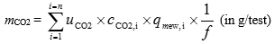
Where:
uCO2 is the ratio between CO2 density and density of the exhaust gas
cCO2,i is the instantaneous CO2 concentration in the exhaust gas, ppm
qmew,i is the instantaneous exhaust mass flow, kg/s
f is the data sampling rate, Hz
n is the number of measurements
Optionally, the CO2 mass may be calculated in accordance with paragraph 8.4.2.4. of Annex 4 by using a CO2 molar mass (MCO2) of 44.01 g/mol.
3.2. Dilute measurement
This paragraph applies, if CO2 is measured in the dilute exhaust gas.
3.2.1. Measurement
CO2 in the dilute exhaust gas emitted by the engine submitted for testing shall be measured with a non-dispersive infrared (NDIR) analyser in accordance with paragraph 9.3.2.3. and Appendix 2 to Annex 4. Dilution of the exhaust shall be done with filtered ambient air, synthetic air or nitrogen. The flow capacity of the full flow system shall be large enough to completely eliminate water condensation in the dilution and sampling systems.
The measurement system shall meet the linearity requirements of paragraph 9.2. and Table 7 of Annex 4.
The measurement system shall meet the requirements of paragraphs 9.3.1., 9.3.4. and 9.3.5. of Annex 4.
3.2.2. Data evaluation
The relevant data shall be recorded and stored in accordance with paragraph 7.6.6. of Annex 4.
3.2.3. Calculation of cycle averaged emission
If measured on a dry basis, the dry/wet correction according to paragraph 8.1. of Annex 4 shall be applied.
For systems with constant mass flow (with heat exchanger), the mass of CO2 (g/test) shall be determined with the following equation:
mCO2 = 0.001519 x cCO2 x med (in g/test)
Where:
cCO2 is the average background corrected CO2 concentration, ppm
0.001519 is the ratio between CO2 density and density of air (u factor)
med is the total diluted exhaust mass over the cycle, kg
For systems with flow compensation (without heat exchanger), the mass of CO2 (g/test) shall be determined by calculating the instantaneous mass emissions and integrating the instantaneous values over the cycle. Also, the background correction shall be applied directly to the instantaneous concentration values. The following equation shall be applied:

Where:
cCO2,e is the CO2 concentration measured in the diluted exhaust gas, ppm
cCO2,d is the CO2 concentration measured in the dilution air, ppm
0.001519 is the ratio between CO2 density and density of air (u factor)
med,i is the instantaneous mass of the diluted exhaust gas, kg
med is the total mass of diluted exhaust gas over the cycle, kg
D is the dilution factor
Optionally, the u factor may be calculated with equation 57 in paragraph 8.5.2.3.1. of Annex 4 by using a CO2 molar mass (MCO2) of 44.01 g/mol.
CO2 background correction shall be applied in accordance with paragraph 8.5.2.3.2. of Annex 4.
3.3. Calculation of brake specific emissions
The cycle work needed for the calculation of brake specific CO2 emissions shall be determined in accordance with paragraph 7.8.6. of Annex 4.
3.3.1. WHTC
The brake specific emissions eCO2 (g/kWh) shall be calculated as follows:

Where:
mCO2, cold is the CO2 mass emissions of the cold start test, g/test
mCO2, hot is the CO2 mass emissions of the hot start test, g/test
Wact, cold is the actual cycle work of the cold start test, kWh
Wact, hot is the actual cycle work of the hot start test, kWh
3.3.2. WHSC
The brake specific emissions eCO2 (g/kWh) shall be calculated as follows:

Where:
mCO2 is the CO2 mass emissions, g/test
Wact is the actual cycle work, kWh
4. Determination of fuel consumption
4.1. Measurement
Measurement of the instantaneous fuel flow shall be done by systems that preferably measure mass directly such as the following:
(a) Mass flow sensor;
(b) Fuel weighing;
(c) Coriolis meter.
The fuel flow measurement system shall have the following:
(a) An accuracy of ±2 per cent of the reading or ±0.3 per cent of full scale whichever is better;
(b) A precision of ±1 per cent of full scale or better;
(c) A rise time that does not exceed 5 s.
The fuel flow measurement system shall meet the linearity requirements of paragraph 9.2. and Table 7 of Annex 4.
Precautions shall be taken to avoid measurement errors. Such precautions shall at least include the following:
(a) The careful installation of the device according to the instrument manufacturers" recommendations and to good engineering practice;
(b) Flow conditioning as needed to prevent wakes, eddies, circulating flows, or flow pulsations that affect accuracy or precision of the fuel flow system;
(c) Account for any fuel that bypasses the engine or returns from the engine to the fuel storage tank.
4.2. Data evaluation
The relevant data shall be recorded and stored in accordance with paragraph 7.6.6. of Annex 4.
4.3. Calculation of cycle averaged fuel consumption
The mass of fuel (g/test) shall be determined by the sum of the instantaneous values over the cycle, as follows:
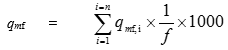
Where:
qmf,i is the instantaneous fuel flow, kg/s
f is the data sampling rate, Hz
n is the number of measurements
4.4. Calculation of brake specific fuel consumption
The cycle work needed for the calculation of the brake specific fuel consumption shall be determined in accordance with paragraph 7.8.6. of Annex 4.
4.4.1. WHTC
The brake specific fuel consumption ef (g/kWh) shall be calculated as follows:

Where:
qmf, cold is the fuel mass of the cold start test, g/test
qmf, hot is the fuel mass of the hot start test, g/test
Wact, cold is the actual cycle work of the cold start test, kWh
Wact, hot is the actual cycle work of the hot start test, kWh
4.4.2. WHSC
The brake specific fuel consumption ef (g/kWh) shall be calculated as follows:

Where:
qmf is the fuel mass, g/test
Wact is the actual cycle work, kWh
Annex 12 ‑ Appendix 1 Provisions on CO2 emissions and fuel consumption for extension of a type approval for a vehicle type-approved under this Regulation with a reference mass exceeding 2,380 kg but not exceeding 2,610 kg
A.1.1. Introduction
A.1.1.1. This appendix sets out the provisions and test procedures for reporting CO2 emissions and fuel consumption for extension of type approval for a vehicle type-approved under this Regulation to a vehicle with a reference mass exceeding 2,380 kg but not exceeding 2,610 kg.
A.1.2. General requirements
A.1.2.1. In order to receive an extension of a type-approval for a vehicle in respect of its engine type-approved under this Regulation to a vehicle with a reference mass exceeding 2,380 kg but not exceeding 2,610 kg, the manufacturer shall meet the requirements relating to the measurement of CO2 emissions and fuel consumption established by the type 1 emissions test procedures set out in Annex B6 to UN Regulation No. 154 with only speed trace and RCB corrections. The CO2 emissions shall be determined in accordance with table A6/2 of that annex not taking into account the criteria emission test results, where the vehicle during testing shall apply no AES and be considered as VH. The test reports specified in Appendix 1, Part I until paragraph 2.1. inclusive, and Appendix 2 to Annex A1 of UN Regulation No. 154, shall be submitted to the type approval authorities including the results of pollutant emissions.
The manufacturer shall provide the type approval authority with a signed declaration that all variants and versions for which this extension is requested are in conformity with the type-approval emission requirements in this Regulation and that the type 1 test was performed in compliance with the previous paragraph.
For dedicated compression ignition engines fuelled with ethanol (ED95), a fixed carbon-hydrogen-oxygen ratio shall be used for the purposes of calculating fuel consumption values, which shall be C1H2.92O0.46.
A.1.2.1.2. Paragraph 5.2.4. of Regulation No. 101 shall be understood as follows:
(1) Density: measured on the test fuel according to ISO 3675 or an equivalent method. For petrol, diesel, ethanol (E85) and ethanol for dedicated C.I. engines (ED95) the density measured at 288 K (15 °C) will be used; for LPG and natural gas/biomethane a reference density shall be used, as follows:
0.538 kg/litre for LPG;
0.654 kg/m3 for NG.
(2) Hydrogen-carbon-oxygen ratio: fixed values shall be used which are:
C1H1.93O0.032 for petrol (E10);
C1H1.86O0.006 for diesel (B7);
C1H2.525 for LPG (liquefied petroleum gas);
CH4 for NG (natural gas) and biomethane;
C1H2.74O0.385 for ethanol (E85);
C1H2.92O0.46 for ethanol for dedicated C.I. engines (ED95).
A.1.2.1.3. Paragraph 1.4.3. of Annex 6. of Regulation No. 101 shall be understood as:
"1.4.3. The fuel consumption, expressed in litres per 100 km (in the case of petrol, LPG, ethanol (E85 and ED95) and diesel) or in m3 per 100 km (in the case of NG/biomethane) is calculated by means of the following formulae:
(a) For vehicles with a positive ignition engine fuelled with petrol (E10):
FC = (0.120/D) ∙ [(0.831 ∙ HC) + (0.429 ∙ CO) + (0.273 ∙ CO2)]
(b) For vehicles with a positive ignition engine fuelled with LPG:
FCnorm = (0.1212/0.538) ∙ [(0.825 ∙ HC) + (0.429 ∙ CO) + (0.273 ∙ CO2)]
If the composition of the fuel used for the test differs from the composition that is assumed for the calculation of the normalised consumption, on the manufacturer’s request a correction factor cf may be applied, as follows:
FCnorm = (0.1212/0.538) ∙ (cf) ∙ [(0.825 ∙ HC) + (0.429 ∙ CO) + (0.273 ∙ CO2)]
The correction factor cf, which may be applied, is determined as follows:
cf = 0.825 + 0.0693 nactual
Where:
nactual is the actual H/C ratio of the fuel used
(c) For vehicles with a positive ignition engine fuelled with NG/biomethane:
FCnorm = (0.1336/0.654) ∙ [(0.749 ∙ HC) + (0.429 ∙ CO) + (0.273 ∙ CO2)]
(d) For vehicles with a positive ignition engine fuelled with ethanol (E85):
FC = (0.1742/D) ∙ [(0.574 ∙ HC) + (0.429 ∙ CO) + (0.273 ∙ CO2)]
(e) For vehicles with a compression ignition engine fuelled with diesel (B7):
FC = (0.1165/D) ∙ [(0.859 ∙ HC) + (0.429 ∙ CO) + (0.273 ∙ CO2)]
(f) For vehicles with a dedicated compression ignition engine fuelled with ethanol (ED95)
FC = (0.186/D) ∙ [(0.538 ∙ HC) + (0.429 ∙ CO) + (0.273 ∙ CO2)]
In these formulae:
FC is the fuel consumption in litre per 100 km (in the case of petrol, ethanol, LPG, diesel or biodiesel) or in m3 per 100 km (in the case of natural gas)
HC is the measured emission of hydrocarbons in g/km
CO is the measured emission of carbon monoxide in g/km
CO2 is the measured emission of carbon dioxide in g/km
D is the density of the test fuel.
In the case of gaseous fuels this is the density at 288 K (15 °C).
Annex 13 Type approval of replacement pollution control devices as separate technical unit
1. Introduction
1.1. This annex contains additional requirements for the type approval of replacement pollution control devices as separate technical units.
1.2. Definition
1.2.1. "Type of pollution control device" means catalytic converters and particulate filters which do not differ in any of the following essential aspects:
(a) Number of substrates, structure and material;
(b) Type of activity of each substrate;
(c) Volume, ratio of frontal area and substrate length;
(d) Catalyst material content;
(e) Catalyst material ratio;
(f) Cell density;
(g) Dimensions and shape;
(h) Thermal protection.
2. General requirements
2.1. Marking
2.1.1. Each replacement pollution control device shall bear at least the following identifications:
(a) The manufacturer’s name or trade mark;
(b) The make and identifying part number of the replacement pollution control device as recorded in the information document issued in accordance with the model set out in Appendix 1 to this annex.
2.1.2. Each original replacement pollution control device shall bear at least the following identifications:
(a) The vehicle or engine manufacturer’s name or trade mark;
(b) The make and identifying part number of the original replacement pollution control device as recorded in the information referred to in paragraph 2.3.
2.2. Documentation
2.2.1. Each replacement pollution control device shall be accompanied by the following information:
(a) The manufacturer’s name or trade mark;
(b) The make and identifying part number of the replacement pollution control device as recorded in the information document issued in accordance with the model set out in Appendix 1 to this annex;
(c) The vehicles or engines including year of manufacture for which the replacement pollution control device is approved, including, where applicable, a marking to identify if the replacement pollution control device is suitable for fitting to a vehicle that is equipped with an on-board diagnostic (OBD) system;
(d) Installation instructions.
The information referred to in this point shall be available in the product catalogue distributed to points of sale by the manufacturer of replacement pollution control devices.
2.2.2. Each original replacement pollution control device shall be accompanied by the following information:
(a) The vehicle or engine manufacturer’s name or trade mark;
(b) The make and identifying part number of the original replacement pollution control device as recorded in the information mentioned in paragraph 2.3.;
(c) The vehicles or engines for which the original replacement pollution control device is of a type covered by paragraph 3.2.12.2.1. of Part 1 of Annex 1, including, where applicable, a marking to identify if the original replacement pollution control device is suitable for fitting to a vehicle that is equipped with an on-board diagnostic (OBD) system;
(d) Installation instructions.
This information referred to in this point shall be available in the product catalogue distributed to points of sale by the vehicle or engine manufacturer.
2.3. For an original replacement pollution control device, the vehicle or engine manufacturer shall provide to the Type Approval Authority the necessary information in electronic format which makes the link between the relevant part numbers and the type approval documentation.
This information shall contain the following:
(a) Make(s) and type(s) of vehicle or engine;
(b) Make(s) and type(s) of original replacement pollution control device;
(c) Part number(s) of original replacement pollution control device;
(d) Type approval number of the relevant engine or vehicle type(s).
3. Separate technical unit type approval mark
3.1. Every replacement pollution control device conforming to the type approved under this Regulation as a separate technical unit shall bear a type approval mark.
3.2. The type approval mark referred to in paragraph 3.1. shall consist of:
3.2.1. A circle surrounding the letter "E" followed by the distinguishing number of the country which has granted the type approval (see paragraph 4.12.3.1. of this Regulation);
3.2.2. The number of this Regulation, followed by the letter "R", a dash and the approval number to the right of the circle prescribed in paragraph 3.2.1.;
3.2.3. The letters "RD" after the national symbol, the purpose of which is to distinguish that the type approval has been granted for a replacement pollution control device.
3.3. The type approval mark shall be affixed to the replacement pollution control device in such a way as to be clearly legible and indelible. It shall, wherever possible, be visible when the replacement pollution control device is installed on the vehicle.
3.4. An example of the type approval mark for a separate technical unit is given in Appendix 3 to this annex.
3.5. Notice of approval or of extension or of refusal of approval or production definitively discontinued of a replacement pollution control device pursuant to this Regulation shall be communicated to the Parties to the 1958 Agreement which apply this Regulation, by means of a form conforming to the model in Appendix 2 to this annex. Values measured during the type test shall also be shown.
4. Technical requirements
4.1. General requirements
4.1.1. The replacement pollution control device shall be designed, constructed and capable of being mounted so as to enable the engine and vehicle to comply with the rules with which it was originally in compliance and that pollutant emissions are effectively limited throughout the normal life of the vehicle under normal conditions of use.
4.1.2. The installation of the replacement pollution control device shall be at the exact position of the original equipment pollution control device, and the position on the exhaust line of the exhaust gas, temperature and pressure sensors shall not be modified.
4.1.3. If the original equipment pollution control device includes thermal protections, the replacement pollution control device shall include equivalent protections.
4.1.4. Upon request of the applicant for the type approval of the replacement component, the Type Approval Authority that granted the original type approval of the engine system shall make available on a non-discriminatory basis, the information referred to in paragraphs 3.2.12.2.6.8.1.1. and 3.2.12.2.6.8.2.1. in Part 1 of the information document contained in Annex 1 for each engine to be tested.
4.2. General durability requirements
The replacement pollution control device shall be durable, that is designed, constructed and capable of being mounted so that reasonable resistance to the corrosion and oxidation phenomena to which it is exposed is obtained, having regard to the conditions of use of the vehicle.
The design of the replacement pollution control device shall be such that the elements active in controlling emissions are adequately protected from mechanical shock so as to ensure that pollutant emissions are effectively limited throughout the normal life of the vehicle under normal conditions of use.
The applicant for type approval shall provide to the Type Approval Authority details of the test used to establish robustness to mechanical shock and the results of that test.
4.3. Requirements regarding emissions
4.3.1. Outline of procedure for evaluation of emissions
The engines indicated in paragraph 3.4.4. (a) of this Regulation equipped with a complete emissions control system including the replacement pollution control device of the type for which approval is requested, shall be subjected to tests appropriate for the intended application as described in Annex 4, in order to compare its performance with the original emissions control system according to the procedure described below.
4.3.1.1. Where the replacement pollution control device does not comprise the complete emissions control system, only new original equipment or new original replacement pollution control components shall be used to provide a complete system.
4.3.1.2. The emissions control system shall be aged according to the procedure described in paragraph 4.3.2.4. and retested to establish the durability of its emissions performance.
The durability of a replacement pollution control device is determined from a comparison of the 2 successive sets of exhaust gas emissions tests.
(a) The first set is that made with the replacement pollution control device which has been run in with 12 WHSC cycles;
(b) The second set is that made with the replacement pollution control device which has been aged by the procedures detailed below.
Where approval is applied for different types of engines from the same engine manufacturer, and provided that these different types of engines are fitted with an identical original equipment pollution control system, the testing may be limited to at least two engines selected after agreement with the Type Approval Authority.
4.3.2. Procedure for evaluation of emissions performance of a replacement pollution control device
4.3.2.1. The engine or engines shall be fitted with a new original equipment pollution control device according to paragraph 4.11.4. of this Regulation.
The exhaust after-treatment system shall be preconditioned with 12 WHSC cycles. After this preconditioning, the engines shall be tested according to the WHDC test procedures specified in Annex 4. Three exhaust gas tests of each appropriate type shall be performed.
The test engines with the original exhaust after-treatment system or original replacement exhaust after-treatment system shall comply with the limit values according to the type approval of the engine or vehicle.
4.3.2.2. Exhaust gas test with replacement pollution control device
The replacement pollution control device to be evaluated shall be fitted to the exhaust after-treatment system tested according to the requirements of paragraph 4.3.2.1., replacing the relevant original equipment exhaust after-treatment device.
The exhaust after-treatment system incorporating the replacement pollution control device shall then be preconditioned with 12 WHSC cycles. After this preconditioning, the engines shall be tested according to the WHDC procedures described in Annex 4. Three exhaust gas tests of each appropriate type shall be performed.
4.3.2.3. Initial evaluation of the emission of pollutants of engines equipped with replacement pollution control devices.
The requirements regarding emissions of the engines equipped with the replacement pollution control device shall be deemed to be fulfilled if the results for each regulated pollutant (CO, HC, NMHC, methane, NOx, NH3, particulate mass and particle number as appropriate for the type approval of the engine) meet the following conditions:
(1) M ≤ 0.85S + 0.4G
(2) M ≤ G
Where:
M: mean value of the emissions of one pollutant obtained from the three tests with the replacement pollution control device;
S: mean value of the emissions of one pollutant obtained from the three tests with the original or original replacement pollution control device;
G: limit value of the emissions of one pollutant according to the type approval of the vehicle.
4.3.2.4. Durability of emissions performance
The exhaust after-treatment system tested in accordance with paragraph 4.3.2.2. and incorporating the replacement pollution control device shall be subjected to the durability procedures described in Appendix 4 to this annex.
4.3.2.5. Exhaust gas test with aged replacement pollution control device
The aged exhaust after-treatment system incorporating the aged replacement control device shall then be fitted to the test engine used in paragraphs 4.3.2.1. and 4.3.2.2.
The aged exhaust after-treatment systems shall be preconditioned with 12 WHSC cycles and subsequently tested using the WHDC procedures described in Annex 4. Three exhaust gas tests of each appropriate type shall be performed.
4.3.2.6. Determination of ageing factor for the replacement pollution control device
The ageing factor for each pollutant shall be the ratio of the applied emission values at the useful life end point and at the start of the service accumulation. (e.g. if the emissions of pollutant A at the useful life end point are 1.50 g/kWh and those at the start of the service accumulation are 1.82 g/kWh, the ageing factor is 1.82/1.50 = 1.21).
4.3.2.7. Evaluation of the emission of pollutants of engines equipped with replacement pollution control devices
The requirements regarding emissions of the engines equipped with the aged replacement pollution control device (as described in paragraph 4.3.2.5.) shall be deemed to be fulfilled if the results for each regulated pollutant (CO, HC, NMHC, methane, NOx, NH3, particulate mass and particle number as appropriate for the type approval of the engine) meet the following condition:
M*AF ≤ G
Where:
M: mean value of the emissions of one pollutant obtained from the three tests with the preconditioned replacement pollution control device before ageing (i.e. results from paragraph 4.3.2.);
AF: the ageing factor for one pollutant;
G: limit value of the emissions of one pollutant according to the type approval of the vehicle(s).
4.3.3. Replacement pollution control device technology family
The manufacturer may identify a replacement pollution control device technology family, to be identified by basic characteristics which shall be common to devices within the family.
To belong to the same replacement pollution control device technology family the replacement pollution control devices shall have the following:
(a) The same emissions control mechanism (oxidation catalyst, three-way catalyst, particulate filter, selective catalytic reduction for NOx etc.);
(b) The same substrate material (same type of ceramic, or same type of metal);
(c) The same substrate type and cell density;
(d) The same catalytically active materials and, where more than one, the same ratio of catalytically active materials;
(e) The same total charge of catalytically active materials;
(f) The same type of washcoat applied by the same process.
4.3.4. Assessment of the durability of emissions performance of a replacement pollution control device by use of a technology family ageing factor.
Where the manufacturer has identified a replacement pollution control technology family, the procedures described in paragraph 4.3.2. may be used to determine the ageing factors for each pollutant for the parent of that family. The engine on which these tests are conducted shall have a minimum engine displacement of 0.75 dm³ per cylinder.
4.3.4.1. Determination of durability performance of family members
A replacement pollution control device A within a family and intended to be mounted on an engine of displacement CA may be considered to have the same ageing factors as the parent replacement pollution control device P, determined on an engine of displacement CP, if the following conditions are fulfilled:
VA/CA ≥ VP/CP
Where:
VA: Substrate volume (in dm³) of replacement pollution control device A
VP: Substrate volume (in dm³) of the parent replacement pollution control device P of the same family
and
both engines use the same method for regeneration of any emissions control devices incorporated in the original exhaust after-treatment system. This requirement shall apply only where devices requiring regeneration are incorporated in the original exhaust after-treatment system.
If these conditions are fulfilled, the emissions durability performance of other members of the family may be determined from the emissions results (S) of that family member determined according to the requirements set out in paragraphs 4.3.2.1., 4.3.2.2. and 4.3.2.3. and using the ageing factors determined for the parent of that family.
4.3.5. Fuels
In the case described in paragraph 4.6.2. to this Regulation, the test procedure laid down in paragraphs 4.3.1. to 4.3.2.7. of this annex shall be conducted with the fuels declared by the manufacturer of the original engine system. However, in agreement with the Type Approval Authority, the durability procedure set out in Appendix 4 and referred to in paragraph 4.3.2.4. may be performed only with the fuel which represents the worst case in terms of ageing.
4.4. Requirements regarding exhaust back-pressure
The back pressure shall not cause the complete exhaust system to exceed the value specified according to paragraph 6.1.2. of this Regulation.
4.5. Requirements regarding OBD compatibility (applicable only to replacement pollution control devices intended to be fitted to vehicles equipped with an OBD system)
4.5.1. OBD compatibility demonstration is required only when the original pollution control device was monitored in the original configuration.
4.5.2. The compatibility of the replacement pollution control device with the OBD system shall be demonstrated by using the procedures described in Annex 9B for replacement pollution control devices intended to be fitted to engines or vehicles type-approved in accordance with this Regulation.
4.5.3. The provisions in this Regulation applicable to components other than pollution control devices shall not apply.
4.5.4. The replacement pollution control device manufacturer may use the same preconditioning and test procedure as used during the original type approval. In this case, the Type Approval Authority which granted original type approval of an engine of a vehicle shall provide, on request and on a non-discriminatory basis, appendix on test conditions to Annex 1 which contains the number and type of preconditioning cycles and the type of test cycle used by the original equipment manufacturer for OBD testing of the pollution control device.
4.5.5. In order to verify the correct installation and functioning of all other components monitored by the OBD system, the OBD system shall indicate no malfunction and have no stored fault codes prior to the installation of any of the replacement pollution control device. An evaluation of the status of the OBD system at the end of the tests described in paragraphs 4.3.2. to 4.3.2.7. may be used for this purpose.
4.5.6. The malfunction indicator shall not activate during vehicle operation required by paragraphs 4.3.2. to 4.3.2.7.
4.6. Requirements regarding compatibility with the NOx control measures (applicable only to replacement pollution control devices to be fitted to vehicles equipped with sensors directly measuring NOx concentration in the exhaust).
4.6.1. NOx control measures compatibility demonstration is required only when the original pollution control device was monitored in the original configuration.
4.6.2. The compatibility of the replacement pollution control device with the NOx control measures shall be demonstrated by using the procedures described in Annex 11 to this Regulation, for replacement pollution control devices intended to be fitted to engines or vehicles type approved in accordance with this Regulation.
4.6.3. Reserved
4.6.4. The replacement pollution control device manufacturer may use the same preconditioning and test procedure as used during the original type approval. In that case, the approval authority which granted original type approval of an engine of a vehicle shall provide, on request and on a non-discriminatory basis, an information document presented as an appendix to the Information Document provided for in Annex I, which contains the number and type of preconditioning cycles and the type of test cycle used by the original equipment manufacturer for NOx control measures testing of the pollution control device.
4.6.5. Paragraph 4.5.5. shall apply to NOx control measures monitored by the OBD system.
5. Conformity of production
5.1. Measures to ensure the conformity of production shall be taken in accordance with paragraph 8. of this Regulation.
5.2. Special provisions
5.2.1. The checks referred to in Appendix 2 to the 1958 Agreement (E/ECE/324//E/ECE/TRANS/505/Rev.2) shall include compliance with the characteristics as defined under "type of pollution control device" in paragraph 1.2.1.
5.2.2. For the application of paragraph 8. of this Regulation, the tests described in paragraph 4.3. of this annex (requirements regarding emissions) may be carried out. In this case, the holder of the approval may request, as an alternative, to use as a basis for comparison not the original equipment pollution control device, but the replacement pollution control device which was used during the type approval tests (or another sample that has been proven to conform to the approved type). Emissions values measured with the sample under verification shall then on average not exceed by more than 15 per cent the mean values measured with the sample used for reference.
Annex 13 ‑ Appendix 1 Model information document
Information document No
relating to the type approval of replacement pollution control devices
The following information shall be supplied in triplicate and include a list of contents. Any drawings shall be supplied in appropriate scale and sufficient detail on size A4 or on a folder of A4 format. Photographs, if any, shall show sufficient detail.
If the systems, components or separate technical units have electronic controls, information concerning their performance shall be supplied.
0. General
0.1. Make (trade name of manufacturer):
0.2. Type:
0.2.1. Commercial name(s) (if available):
0.3. Means of identification of type:
0.5. Name and address of manufacturer:
0.7. In the case of components and separate technical units, location and method of affixing of the approval mark:
0.8. Name(s) and address(es) of assembly plant(s):
0.9 Name and address of the manufacturer’s authorised representative (if any):
1. Description of the device
1.1. Type of the replacement pollution control device: (oxidation catalyst, three-way catalyst, SCR catalyst, particulate filter etc.):
1.2. Drawings of the replacement pollution control device, identifying in particular all the characteristics referred to under "type of pollution control device" in paragraph 1.2.1. of this annex:
1.3. Description of the engine and vehicle type or types for which the replacement pollution control device is intended:
1.3.1. Number(s) and/or symbol(s) characterising the engine and vehicle type(s):
1.3.2. Number(s) and/or symbol(s) characterising the original pollution control device(s) which the replacement pollution control device is intended to replace:
1.3.3. Is the replacement pollution control device intended to be compatible with OBD requirements? (Yes/No)
1.3.4. Is the replacement pollution control device compatible with existing vehicle/engine control systems? (Yes/No)1
1.4. Description and drawings showing the position of the replacement pollution control device relative to the engine exhaust manifold(s):
Section I
0.1. Make (trade name of manufacturer): ...........................
0.2. Type:...............................................
0.3. Means of identification of type marked on the component/separate technical unit3 (Identifying Part Number):
...................................................
0.3.1. Location of that marking:..................................
0.4. Name and address of manufacturer:
...................................................
0.5. In the case of components and separate technical units, location and method of affixing of the approval mark:
0.6. Name and address(es) of assembly plant(s) :
...................................................
0.7. Name and address of manufacturer’s representative:
...................................................
Section II
1. Additional information
1.1. Make and type of the replacement pollution control device: (oxidation catalyst, three-way catalyst, SCR catalyst, particulate filter etc.):
...................................................
1.2. Engine and vehicle type(s) for which the pollution control device type:
...................................................
1.3. Type(s) of engine on which the replacement pollution control device has been tested:
1.3.1. Has the replacement pollution control device demonstrated compatibility with OBD requirements (Yes/No)4
2. Technical Service responsible for carrying out the tests:
...................................................
3. Date of test report:.......................................
4. Number of test report:....................................
5. Remarks:
...................................................
__________________
3 If the means of identification of type contains characters not relevant to describe the vehicle, component or separate technical unit types covered by this type approval certificate such characters shall be represented in the document by the symbol:"?"
(e.g. ABC??123??).
4 Delete where not applicable
6. Place:...............................................
7. Date:................................................
8. Signature:............................................
Attachments: Information package.
Test report.
Annex 13 ‑ Appendix 3 Arrangement of approval mark
This appendix provides details on the arrangement of the approval mark issued and affixed to a replacement pollution control device in conformity with paragraph 3. of this annex
The following schematic presents the general lay-out, proportions and contents of the marking. The meaning of numbers and alphabetical character are identified, and sources to determine the corresponding alternatives for each approval case are also referred.
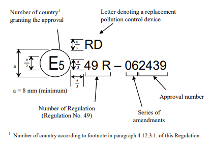
Annex 13 ‑ Appendix 4 Durability procedure for evaluation of emissions performance of a replacement pollution control device
1. This Appendix sets out the durability procedure referred to in paragraph 4.3.2.4. of Annex 13, for the purpose of evaluating the emissions performance of a replacement pollution control device.
2. Description of the durability procedure
2.1. The durability procedure shall consist of a data collection phase and a service accumulation schedule.
2.2. Data collection phase
2.2.1. The selected engine, equipped with the complete exhaust after-treatment system incorporating the replacement pollution control device, shall be cooled down to ambient temperature and run one cold start WHTC test-cycle in accordance with paragraphs 7.6.1. and 7.6.2. of Annex 4 to this Regulation.
2.2.2. Immediately after the cold start WHTC test-cycle, the engine shall be run for nine consecutive hot start WHTC test-cycles in accordance with paragraph 7.6.4. of Annex 4 to this Regulation.
2.2.3. The test sequence set out in paragraphs 2.2.1. and 2.2.2. shall be carried out in accordance with the instructions laid down in paragraph 7.6.5. of Annex 4 to this Regulation.
2.2.4. Alternatively, the relevant data can be collected by driving a fully loaded vehicle equipped with the selected exhaust after-treatment system incorporating the replacement pollution control device. The test can be carried out either on the road following the trip requirements of paragraphs 4.5. to 4.5.5. of Annex 8 to this Regulation with comprehensive recording of the driving data, or on a suitable chassis dynamometer. If an on-road test is chosen, the vehicle shall be driven over a cold test-cycle, as set out in Appendix 6 to this annex, followed by nine hot test-cycles, identical to the cold one, in a way that the work developed by the engine is the same as the one achieved under paragraphs 2.2.1. and 2.2.2. If a chassis dynamometer is chosen, the simulated road gradient of the test-cycle in Appendix 6 shall be adapted to match the work developed by the engine over the WHTC.
2.2.5. The Type Approval Authority shall refuse the temperature data obtained under paragraph 2.2.4. if it deems those data to be unrealistic and shall request either the repetition of the test, or the carrying out of a test pursuant to paragraphs 2.2.1., 2.2.2. and 2.2.3.
2.2.6. Temperatures in the replacement pollution control device shall be recorded during the whole test sequence, at the location with the highest temperature.
2.2.7. In cases where the location with the highest temperature varies over time, or where that location is difficult to define, multiple bed temperatures should be recorded at suitable locations.
2.2.8. The number and locations of the temperature measurements shall be selected by the manufacturer, in agreement with the Type Approval Authority, based on best engineering judgement.
2.2.9. With the agreement of the Type Approval Authority, a single catalyst bed temperature or the catalyst inlet temperature may be used if measuring multiple bed temperatures is proven to be unfeasible or too difficult.
Figure 1
Example of temperature sensors location in a generic after-treatment device

Figure 2
Example of temperature sensors location for DPF

2.2.10. The temperatures shall be measured and recorded at a minimum rate of once every second (1 Hz) during the test sequence.
2.2.11. The measured temperatures shall be tabulated into a histogram with temperature bins no larger than 10 ºC. In the case mentioned in paragraph 2.2.7., the highest temperature each second shall be the one recorded in the histogram. Each bar of the histogram shall represent the cumulated frequency in seconds of the measured temperatures falling in the specific bin.
2.2.12. The time in hours corresponding to each temperature bin must be determined and then extrapolated to the useful life of the replacement pollution control device, in accordance with the values specified in Table 1. The extrapolation shall be based on the assumption that one WHTC cycle corresponds to 20 km driving.
Table 1
Useful life of the replacement pollution control device for each vehicle category, and equivalent WHTC test-cycles and hours of operation
Vehicle category | Mileage (km) | Equivalent number of WHTC test-cycles | Equivalent number of hours |
Engine systems fitted to vehicles of category M1, N1 and N2 | 114 286 | 5 714 | 2 857 |
Engine systems fitted to vehicles of category N2, N3 with a maximum technically permissible mass not exceeding 16 tonnes and M3 Class I, Class II and Class A, and Class B with a maximum technically permissible mass exceeding 7.5 tonnes | 214 286 | 10 714 | 5 357 |
Engine systems fitted to vehicles of category N3 with a maximum technically permissible mass exceeding 16 tonnes, and M3, Class III and Class B with a maximum technically permissible mass exceeding 7.5 tonnes | 500 000 | 25 000 | 12 500 |
2.2.13. It is allowed to perform the data collection phase for different devices at the same time.
2.2.14. In the case of systems operating in the presence of active regeneration, the number, length and temperatures of the regenerations occurring during the test sequence defined in paragraphs 2.2.1. and 2.2.2. shall be recorded. If no active regeneration has occurred, the hot sequence defined in paragraph 2.2.2. shall be extended in order to include at least two active regenerations.
2.2.15. The total lubricant consumed during the data collection period, in g/h, shall be recorded, using any suitable method, as for example the drain and weigh procedure described in Appendix 6. For this purpose, the engine shall be run during 24 hours, performing consecutive WHTC test-cycles. In cases where an accurate measurement of oil consumption cannot be obtained, the manufacturer, in agreement with the Type Approval Authority, may use the following options for the determination of the lubricant consumption:
(a) A default value of 30 g/h;
(b) A value requested by the manufacturer, based on sound data and information, and agreed with the Type Approval Authority.
2.3. Calculation of the equivalent ageing time corresponding to a reference temperature
2.3.1. The temperatures recorded pursuant to paragraphs 2.2. to 2.2.15. shall be reduced to a reference temperature Tr, requested by the manufacturer in agreement with the Type Approval Authority, within the range of the temperatures recorded during the data collection phase.
2.3.2. In the case specified in paragraph 2.2.13., the value of Tr for each one of the devices may vary.
2.3.3. The equivalent ageing time corresponding to the reference temperature shall be calculated, for each bin referred to in 2.2.11., in accordance with the following equation:
Equation 1:
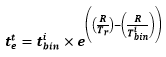
Where:
R = thermal reactivity of the replacement pollution control device.
The following values shall be used:
Diesel Oxidation Catalyst (DOC): 18,050
Catalysed DPF: 18,050
SCR or ammonia oxidation catalyst (AMOX) based on iron-zeolite
(Fe-Z): 5,175
SCR copper-zeolite (Cu-Z): 11,550
SCR Vanadium (V): 5,175
LNT (lean-NOx trap): 18,050
Tr = reference temperature, in K.
 = midpoint temperature, in K, of the temperature bin i to which the replacement pollution control device is exposed during the data collection phase, registered in the temperature histogram.
 = the time, in hours, corresponding to the temperature, adjusted to a full useful life basis e.g. if the histogram represented 5 hours, and useful life is 4,000 hours according to Table 1, all histogram time entries would be multiplied by (4,000/5)=800.
 = the equivalent ageing time, in hours, needed to achieve, by exposing the replacement pollution control device at the temperature Tr, the same amount of ageing as the one that would result from exposure of the replacement pollution control device at the temperature during the time
i = bin number, where 1 is number for the bin with the lowest temperature and n the value for the bin with the highest temperature.
Equation 2:

AT = total equivalent ageing time, in hours, needed to achieve, by exposing the replacement pollution control device at the temperature Tr, the same amount of ageing as the one that would result from exposure of the replacement pollution control device, over its useful life, to the temperature during the time of each one of the i bins registered in the histogram.
= the equivalent ageing time, in hours, needed to achieve, by exposing the replacement pollution control device at the temperature Tr, the same amount of ageing as the one that would result from exposure of the replacement pollution control device at the temperature during the time .
i = bin number, where 1 is number for the bin with the lowest temperature and n the value for the bin with the highest temperature.
n = total number of temperature bins.
2.3.5. In the case referred to in paragraph 2.2.13., AT shall be calculated for each device.
2.4. Service accumulation schedule
2.4.1. General requirements
2.4.1.1. The service accumulation schedule shall allow acceleration of the ageing of the replacement pollution control device, using the information gathered during the data collection phase set out in paragraph 2.2.
2.4.1.2. The service accumulation schedule shall consist of a thermal accumulation schedule and a lubricant consumption accumulation schedule in accordance with paragraph 2.4.4.6. The manufacturer, in agreement with the Type Approval Authority, may not have to carry out a lubricant consumption accumulation schedule in case the replacement pollution control devices are placed downstream of an after-treatment filter component (e.g. diesel particulate filter). Both the thermal accumulation schedule and the lubricant consumption accumulation schedule shall consist of a repetition of, respectively, a series of thermal and lubricant consumption sequences.
2.4.1.3. In the case of replacement pollution control devices operating in the presence of active regeneration, the thermal sequence shall be complemented with an active regeneration mode.
2.4.1.4. For service accumulation schedules consisting of both thermal and lubricant consumption accumulation schedules, their respective sequences shall be alternated, so that for each thermal sequence that has to be performed, the following sequence corresponds to lubricant consumption.
2.4.1.5. It is allowed to perform the service accumulation schedule at the same time for different devices. In that case, a single service accumulation schedule shall be set for all the devices.
2.4.2. Thermal accumulation schedule
2.4.2.1. The thermal accumulation schedule shall simulate the effect of thermal ageing on the performance of a replacement pollution control device until the end of its lifetime.
2.4.2.2. The engine used for the performance of the service accumulation schedule, fitted with the exhaust after-treatment system incorporating the replacement pollution control device, is operated for a minimum of three consecutive thermal sequences, as set out in Appendix 5.
2.4.2.3. The temperatures shall be recorded over a minimum of two thermal sequences. The first sequence, conducted for warming up, shall not be taken into account for the purpose of temperature gathering.
2.4.2.4. The temperatures shall be recorded at suitable locations, chosen in accordance with paragraphs 2.2.6. to 2.2.9., at a minimum rate of once every second (1 Hz).
2.4.2.5. The effective ageing time corresponding to the thermal sequences referred to in paragraph 2.4.2.3., shall be calculated in accordance with the following equations:
Equation 3:

Equation 4:

Where:
 = the effective ageing time, in hours, needed to achieve, by exposing the replacement pollution control device at the temperature Tr, the same amount of ageing as the one that would result from exposure of the replacement pollution control device at the temperature Ti during the second i.
Ti = the temperature, in K, measured in the second i, in each one of the thermal sequences.
R = thermal reactivity of the replacement pollution control device. The manufacturer shall agree with the Type Approval Authority on the R value to be used. It will also be possible, as alternative, to use the following default values:
Diesel Oxidation Catalyst (DOC): 18,050
Catalysed DPF: 18,050
SCR or ammonia oxidation catalyst (AMOX) based on iron-zeolite
(Fe-Z): 5,175
SCR copper-zeolite (Cu-Z): 11,550
SCR Vanadium (V): 5,175
LNT (lean-NOx trap): 18,050
Tr = reference temperature, in K, being the same value as in equation 1.
AE = effective ageing time, in hours, needed to achieve, by exposing the replacement pollution control device at the temperature Tr, the same amount of ageing as the one that would result from exposure of the replacement pollution control device during the duration of the thermal sequence.
AT = total equivalent ageing time, in hours, needed to achieve, by exposing the replacement pollution control device at the temperature Tr, the same amount of ageing as the one that would result from exposure of the replacement pollution control device, over its useful life, to the temperature  during the time
  of each one of the i bins registered in the histogram.
i = number of temperature measurement.
p = total number of temperature measurements.
nc = thermal sequence number, of those conducted for the purpose of temperature gathering, in accordance with paragraph 2.4.2.3.
C = total number of thermal sequences conducted for the purpose of temperature gathering.
2.4.2.6. The total number of thermal sequences to be included in the service accumulation schedule shall be determined by applying the following equation:
Equation 5:
NTS = AT/AE
Where:
NTS = total number of thermal sequences to be carried out during the service accumulation schedule.
AT = total equivalent ageing time, in hours, needed to achieve, by exposing the replacement pollution control device at the temperature Tr, the same amount of ageing as the one that would result from exposure of the replacement pollution control device, over its useful life, to the temperature  during the time
  of each one of the i bins registered in the histogram.
AE = effective ageing time, in hours, needed to achieve, by exposing the replacement pollution control device at the temperature Tr, the same amount of ageing as the one that would result from exposure of the replacement pollution control device during the duration of the thermal sequence.
2.4.2.7. It is allowed to reduce NTS and, consequently the service accumulation schedule, by increasing the temperatures at which each device is exposed at each mode of the ageing cycle through the application of one or several of the following measures:
(a) Insulating the exhaust pipe;
(b) Moving the replacement pollution control device closer to the exhaust manifold;
(c) Artificially heating up the temperature of the exhaust;
(d) Optimizing the engine settings without substantially changing the emission behaviour of the engine.
2.4.2.8. When applying the measures referred to in paragraphs 2.4.4.6. and 2.4.4.7., the total ageing time calculated from NTS shall not be less than 10 per cent of the useful life listed in Table 1, e.g. the vehicle category N1 shall not have an NTS of less than 286 thermal sequences, assuming that each sequence is 1 hour long.
2.4.2.9. It is allowed to increase NTS and, consequently, the duration of the service accumulation schedule, by lowering the temperatures at each mode of the ageing cycle through the application of one or several of the following measures:
(a) Moving the replacement pollution control device further away from the exhaust manifold;
(b) Artificially cooling down the temperature of the exhaust;
(c) Optimizing the engine settings.
2.4.2.10. In the case referred to in paragraph 2.4.1.5., the following shall apply:
2.4.2.10.1. NTS shall be the same for each device, so that a single service accumulation schedule can be set up.
2.4.2.10.2. In order to achieve the same NTS for each device, a first NTS value shall be calculated for each device, with its own AT and AE values.
2.4.2.10.3. If the calculated NTS values are different, one or more of the measures set out in paragraphs 2.4.2.7. to 2.4.2.10. may be applied on the device or devices for which NTS needs to be modified, over the thermal sequences referred to in paragraph 2.4.2.3., in order to influence the measured Ti and therefore conveniently speed up or slow down the artificial ageing of the targeted device or devices.
2.4.2.10.4. The new NTS values corresponding to the new temperatures Ti obtained in paragraph 2.4.2.10.3. shall be calculated.
2.4.2.10.5. The steps set out in paragraphs 2.4.2.10.3. and 2.4.2.10.4. shall be repeated until the NTS values obtained for each device in the system match.
2.4.2.10.6. The Tr values used for obtaining the different NTS in paragraphs 2.4.2.10.4. and 2.4.2.10.5. shall be the same ones as those used in paragraphs 2.3.2. and 2.3.5. for calculating AT for each device.
2.4.2.11. In the case of an assembly of replacement pollution control devices constituting a system which is to be approved as a separate technical unit, one of the following two options may be considered for the thermal ageing of the devices:
2.4.2.11.1. The devices within the assembly may be either separately or jointly aged, in accordance with paragraph 2.4.2.10.
2.4.2.11.2. If the assembly is built in such a way that it is not possible to decouple the devices (e.g. DOC + SCR in a can), the thermal ageing of the assembly shall be carried out with the highest NTS.
2.4.3. Modified thermal accumulation schedule for devices operating in the presence of active regeneration
2.4.3.1. The modified thermal accumulation schedule for devices operating in the presence of active regeneration shall simulate the effect of ageing due to both thermal load and active regeneration on a replacement pollution control device at the end of its lifetime.
2.4.3.2. The engine used for the service accumulation schedule, fitted with the exhaust after-treatment system incorporating the replacement pollution control device, is operated for a minimum of three modified thermal sequences, consisting each sequence of a thermal sequence as set out in Appendix 5, followed by a complete active regeneration, during which the peak temperature reached in the after-treatment system should be not lower than the peak temperature recorded in the data collection phase.
2.4.3.3. The temperatures shall be recorded over a minimum of two modified thermal sequences. The first sequence, conducted for warming up, shall not be taken into account for the purpose of temperature gathering.
2.4.3.4. In order to minimize the time elapsed between the thermal sequence as set out in Appendix 5 and the subsequent active regeneration, the manufacturer may artificially trigger the active regeneration by running, after each thermal sequence as set out in Appendix 5, the engine at a steady mode that enables a high production of soot by the engine. In that case, the steady mode shall also be considered as part of the modified thermal sequence set out in paragraph 2.4.3.2.
2.4.3.5. The effective ageing time corresponding to each modified thermal sequence shall be calculated using equations 3 and 4.
2.4.3.6. The total number of modified thermal sequences to be conducted during the service accumulation schedule shall be calculated using equation 5.
2.4.3.7. It is allowed to reduce NTS, and consequently the duration of the service accumulation schedule, by increasing the temperatures at each mode of the modified thermal sequence, applying one or several of the measures set out in paragraph 2.4.2.7.
2.4.3.8. In addition to the measures referred to in paragraph 2.4.3.7., NTS can also be reduced by increasing the peak temperature of the active regeneration within the modified thermal sequence, without exceeding a bed temperature of 800 ºC under any circumstances.
2.4.3.9. NTS shall never be less than 50 per cent of the number of active regenerations to which the replacement pollution control device is subjected during its useful life, calculated in accordance with the following equation:
Equation 5:
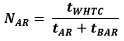
Where:
NAR = number of active regeneration sequences over the useful life of the replacement pollution control device.
tWHTC = equivalent number of hours corresponding to the vehicle category for which the replacement pollution control device is intended, obtained from Table 1.
tAR = duration, in hours, of an active regeneration.
tBAR= time, in hours, between two consecutive active regenerations.
2.4.3.10. If, as consequence of the application of the minimum number of modified thermal sequences as set out in paragraph 2.4.3.9., × NTS calculated using equation 4 exceeds the AT calculated using equation 2, the time of each mode of the thermal sequence set out in Appendix 5, and embedded in the modified thermal sequence as set out in paragraph 2.4.3.2., may be reduced in the same proportion, in order to make AE × NTS = AT.
2.4.3.11. It is allowed to increase NTS and consequently the duration of the service accumulation schedule, by lowering the temperatures at each mode of the thermal-active regeneration sequence by applying one or several of the measures set out in paragraph 2.4.2.9.
2.4.3.12. In the case referred to in paragraphs 2.4.1.5., 2.4.2.10. and 2.4.2.11. shall apply.
2.4.4. Lubricant consumption accumulation schedule
2.4.4.1. The lubricant consumption accumulation schedule shall simulate the effect of ageing due to chemical poisoning or deposit formation as a result of lubricant consumption, on the performance of a replacement pollution control device at the end of its lifetime.
2.4.4.2. The lubricant consumed, in g/h, shall be determined over a minimum of 24 thermal sequences or a corresponding number of modified thermal sequences, using any suitable method, as for example the drain and weigh procedure described in Appendix 7. Fresh lubricant shall be used.
2.4.4.3. The engine shall be equipped with a constant volume oil sump in order to avoid the need of "top-offs", since oil level influences the oil consumption rate. Any suitable method, as for example the one described in the ASTM standard D7156-09, may be used.
2.4.4.4. The theoretical time, in hours, that the thermal accumulation schedule or modified thermal accumulation schedule, as it corresponds, would have to be conducted, in order to obtain the same lubricant consumption as the one corresponding to the useful life of the replacement control device, shall be calculated by applying the following equation:
Equation 6:

Where:
tTAS = theoretical duration, in hours, of the service accumulation schedule required to obtain the same lubricant consumption as the one corresponding to the useful life of the replacement pollution control device, provided that the service accumulation schedule is only made up of a series of consecutive thermal sequences or consecutive modified thermal sequences.
LCRWHTC = lubricant consumption rate, in g/h determined as set out in paragraph 2.2.15.
tWHTC = equivalent number of hours corresponding to the vehicle category for which the replacement pollution control device is intended, obtained from Table 1.
LCRTAS = lubricant consumption rate, in g/h, determined as set out in paragraph 2.4.4.2.
2.4.4.5. The number of thermal sequences or modified thermal sequences corresponding to tTAS shall be calculated by applying the following ratio:
Equation 7:

Where:
N = number of thermal sequences or modified thermal sequences corresponding to tTAS.
tTAS = theoretical duration, in hours, of the service accumulation schedule required to obtain the same lubricant consumption as the one corresponding to the useful life of the replacement pollution control device, provided that the service accumulation schedule was only made up of a series of consecutive thermal sequences or consecutive modified thermal sequences.
tTS = duration, in hours, of a single thermal sequence or modified thermal sequence.
2.4.4.6. The value of N shall be compared to the value of NTS calculated in accordance with paragraph 2.4.2.6. or, for devices operating in the presence of active regeneration, in accordance with paragraph 2.4.3.5. If N ≤ NTS, it is not necessary to add a lubricant consumption accumulation schedule to the thermal accumulation schedule. If N > NTS, a lubricant consumption accumulation schedule shall be added to the thermal accumulation schedule.
2.4.4.7. A lubricant consumption accumulation schedule may not have to be added if, by increasing the lubricant consumption as described in paragraph 2.4.4.8.4., the needed lubricant consumption is already achieved with the conduction of the corresponding thermal accumulation schedule consisting of the performance of NTS thermal sequences or modified thermal sequences.
2.4.4.8. Development of the lubricant consumption accumulation schedule
2.4.4.8.1. The lubricant consumption accumulation schedule shall consist of a number of lubricant consumption sequences repeated several times, each lubricant consumption sequence being alternated with each thermal sequence or each modified thermal sequence.
2.4.4.8.2. Each lubricant consumption sequence shall consist of a steady mode at constant load and speed, the load and the speed being selected in such a way that the lubricant consumption is maximized and effective thermal aging is minimized. The mode shall be determined by the manufacturer in agreement with the Type Approval Authority, based on best engineering judgement.
2.4.4.8.3. The duration of each lubricant consumption sequence shall be determined as follows:
2.4.4.8.3.1. The engine shall be run for an appropriate period of time at the load and speed determined by the manufacturer in accordance with paragraph 2.4.4.8.2. and the lubricant consumed, in g/h, shall be determined using any suitable method, as for example the drain and weigh procedure described in Appendix 7. Lubricant changes are to be completed at the recommended intervals.
2.4.4.8.3.2. The duration of each lubricant consumption sequence shall be calculated by applying the following equation:
Equation 8:
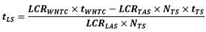
Where:
tLS = the duration, in hours, of a single lubricant consumption sequence LCRWHTC = lubricant consumption rate, in g/h determined as set out in paragraph 2.2.15.
tWHTC = equivalent number of hours corresponding to the vehicle category for which the replacement pollution control device is intended, obtained from Table 1.
LCRTAS = lubricant consumption rate, in g/h, determined as set out in paragraph 2.4.4.2.
LCRLAS = lubricant consumption rate, in g/h, determined as set out in paragraph 2.4.4.8.3.1.
tTS = duration, in hours, of a single thermal sequence, as set out in Appendix 4, or modified thermal sequence, as set out in paragraph 2.4.3.2.
NTS = total number of thermal sequences or modified thermal sequences to be carried out during the service accumulation schedule.
2.4.4.8.4. The lubricant consumption rate shall always remain below 0.5 per cent of the engine fuel consumption rate in order to avoid excessive ash accumulation on the front face of the replacement pollution control device.
2.4.4.8.5. It is allowed to add the thermal ageing due to the conduction of the lubricant consumption sequence to the AE calculated in equation 4.
2.4.5. Development of the complete service accumulation schedule
2.4.5.1. The service accumulation schedule shall be built up alternating a thermal or a modified thermal sequence, as appropriate, with a lubricant consumption sequence. The aforementioned pattern shall be repeated NTS times, being the NTS value the one calculated either in accordance with section 2.4.2. or with section 2.4.3., as appropriate. An example of a complete service accumulation schedule is given in Appendix 8. A flowchart describing the development of a complete service accumulation schedule is given in Appendix 9.
2.4.6. Operation of the service accumulation schedule
2.4.6.1. The engine, fitted with the exhaust after-treatment system incorporating the replacement pollution control device, shall run the service accumulation schedule set out in paragraph 2.4.5.1.
2.4.6.2. The engine used for the performance of the service accumulation schedule may be different to the engine used in the data collection phase, being the latter always the one for which the replacement pollution control device to be type approved has been designed, and the one to be tested for emissions under paragraph 2.4.3.2.
2.4.6.3. If the engine used for the performance of the service accumulation schedule features a larger displacement by 20 per cent or more than the engine used in the data collection phase, the exhaust system of the former should be equipped with a by-pass in order to replicate as closely as possible the exhaust flow rate of the latter at the ageing conditions selected.
2.4.6.4. In the case referred to in paragraph 2.4.6.2., the engine used for the performance of the service accumulation schedule shall be type approved under this Regulation. In addition, if the device or devices under test are intended for being fitted in an engine system with Exhaust Gas Recirculation (EGR), the engine system used for the service accumulation schedule shall also be fitted with an EGR. If the device or devices under test are intended for not being fitted in an engine system with EGR, the engine system used for the service accumulation schedule shall also not be fitted with an EGR.
2.4.6.5. The lubricant and the fuel used in the service accumulation schedule shall be as similar as possible to those used during the data collection phase set out in paragraph 2.2. The lubricant must be in line with the recommendation of the engine manufacturer for which the pollution control device is designed. The fuels used should be market fuels fulfilling the corresponding requirements of the European Directive 98/70/EC. On the request of the manufacturer also reference fuels in accordance with this Regulation can be used.
2.4.6.6. The lubricant shall be changed for maintenance, at the intervals scheduled by the manufacturer of the engine used in the data collection phase.
2.4.6.7. In the case of an SCR, the urea injection shall be performed in accordance with the strategy defined by the manufacturer of the replacement pollution control device.
Annex 13 ‑ Appendix 5 Sequence for thermal ageing
Mode | Speed (% of high idle) | Load (% for a given speed) | Time (s) |
1 | 2.92 | 0.58 | 626 |
2 | 45.72 | 1.58 | 418 |
3 | 38.87 | 3.37 | 300 |
4 | 20.23 | 11.36 | 102 |
5 | 11.37 | 14.90 | 62 |
6 | 32.78 | 18.52 | 370 |
7 | 53.12 | 20.19 | 410 |
8 | 59.53 | 34.73 | 780 |
9 | 78.24 | 54.38 | 132 |
10 | 39.07 | 62.85 | 212 |
11 | 47.82 | 62.94 | 188 |
Regeneration mode (if applicable) | To be defined (see paragraph 2.4.3.4.) | To be defined (see paragraph 2.4.3.4.) | To be defined (see paragraph 2.4.3.4.) |
Lubricant consumption mode (if applicable) | To be defined according to paragraph 2.4.4.8.2. | To be defined according to paragraph 2.4.4.8.2. | To be defined according to paragraph 2.4.4.8.3. |
Note: The sequence of the modes 1 to 11 has been arranged by ascending load in order to maximize the temperature of the exhaust gas in the high load modes. With the agreement of the Type Approval Authority, this order can be modified in order to optimize the temperature of the exhaust gas if this can help in reducing the actual aging time.
Annex 13 ‑ Appendix 6 Test-cycle for chassis dynamometer or on-road data gathering
Time | Speed | Time | Speed | Time | Speed | Time | Speed | Time | Speed | Time | Speed | Time | Speed |
s | km/h | s | km/h | s | km/h | s | km/h | s | km/h | s | km/h | s | km/h |
1 | 0 | 261 | 22.38 | 521 | 35.46 | 781 | 18.33 | 1 041 | 39.88 | 1 301 | 66.39 | 1 561 | 86.88 |
2 | 0 | 262 | 24.75 | 522 | 36.81 | 782 | 18.31 | 1 042 | 41.25 | 1 302 | 66.74 | 1 562 | 86.7 |
3 | 0 | 263 | 25.55 | 523 | 37.98 | 783 | 18.05 | 1 043 | 42.07 | 1 303 | 67.43 | 1 563 | 86.81 |
4 | 0 | 264 | 25.18 | 524 | 38.84 | 784 | 17.39 | 1 044 | 43.03 | 1 304 | 68.44 | 1 564 | 86.81 |
5 | 0 | 265 | 23.94 | 525 | 39.43 | 785 | 16.35 | 1 045 | 44.4 | 1 305 | 69.52 | 1 565 | 86.81 |
6 | 0 | 266 | 22.35 | 526 | 39.73 | 786 | 14.71 | 1 046 | 45.14 | 1 306 | 70.53 | 1 566 | 86.81 |
7 | 2.35 | 267 | 21.28 | 527 | 39.8 | 787 | 11.71 | 1 047 | 45.44 | 1 307 | 71.47 | 1 567 | 86.99 |
8 | 5.57 | 268 | 20.86 | 528 | 39.69 | 788 | 7.81 | 1 048 | 46.13 | 1 308 | 72.32 | 1 568 | 87.03 |
9 | 8.18 | 269 | 20.65 | 529 | 39.29 | 789 | 5.25 | 1 049 | 46.79 | 1 309 | 72.89 | 1 569 | 86.92 |
10 | 9.37 | 270 | 20.18 | 530 | 38.59 | 790 | 4.62 | 1 050 | 47.45 | 1 310 | 73.07 | 1 570 | 87.1 |
11 | 9.86 | 271 | 19.33 | 531 | 37.63 | 791 | 5.62 | 1 051 | 48.68 | 1 311 | 73.03 | 1 571 | 86.85 |
12 | 10.18 | 272 | 18.23 | 532 | 36.22 | 792 | 8.24 | 1 052 | 50.13 | 1 312 | 72.94 | 1 572 | 87.14 |
13 | 10.38 | 273 | 16.99 | 533 | 34.11 | 793 | 10.98 | 1 053 | 51.16 | 1 313 | 73.01 | 1 573 | 86.96 |
14 | 10.57 | 274 | 15.56 | 534 | 31.16 | 794 | 13.15 | 1 054 | 51.37 | 1 314 | 73.44 | 1 574 | 86.85 |
15 | 10.95 | 275 | 13.76 | 535 | 27.49 | 795 | 15.47 | 1 055 | 51.3 | 1 315 | 74.19 | 1 575 | 86.77 |
16 | 11.56 | 276 | 11.5 | 536 | 23.63 | 796 | 18.19 | 1 056 | 51.15 | 1 316 | 74.81 | 1 576 | 86.81 |
17 | 12.22 | 277 | 8.68 | 537 | 20.16 | 797 | 20.79 | 1 057 | 50.88 | 1 317 | 75.01 | 1 577 | 86.85 |
18 | 12.97 | 278 | 5.2 | 538 | 17.27 | 798 | 22.5 | 1 058 | 50.63 | 1 318 | 74.99 | 1 578 | 86.74 |
19 | 14.33 | 279 | 1.99 | 539 | 14.81 | 799 | 23.19 | 1 059 | 50.2 | 1 319 | 74.79 | 1 579 | 86.81 |
20 | 16.38 | 280 | 0 | 540 | 12.59 | 800 | 23.54 | 1 060 | 49.12 | 1 320 | 74.41 | 1 580 | 86.7 |
21 | 18.4 | 281 | 0 | 541 | 10.47 | 801 | 24.2 | 1 061 | 48.02 | 1 321 | 74.07 | 1 581 | 86.52 |
22 | 19.86 | 282 | 0 | 542 | 8.85 | 802 | 25.17 | 1 062 | 47.7 | 1 322 | 73.77 | 1 582 | 86.7 |
23 | 20.85 | 283 | 0.5 | 543 | 8.16 | 803 | 26.28 | 1 063 | 47.93 | 1 323 | 73.38 | 1 583 | 86.74 |
24 | 21.52 | 284 | 0.57 | 544 | 8.95 | 804 | 27.69 | 1 064 | 48.57 | 1 324 | 72.79 | 1 584 | 86.81 |
25 | 21.89 | 285 | 0.6 | 545 | 11.3 | 805 | 29.72 | 1 065 | 48.88 | 1 325 | 71.95 | 1 585 | 86.85 |
26 | 21.98 | 286 | 0.58 | 546 | 14.11 | 806 | 32.17 | 1 066 | 49.03 | 1 326 | 71.06 | 1 586 | 86.92 |
27 | 21.91 | 287 | 0 | 547 | 15.91 | 807 | 34.22 | 1 067 | 48.94 | 1 327 | 70.45 | 1 587 | 86.88 |
28 | 21.68 | 288 | 0 | 548 | 16.57 | 808 | 35.31 | 1 068 | 48.32 | 1 328 | 70.23 | 1 588 | 86.85 |
29 | 21.21 | 289 | 0 | 549 | 16.73 | 809 | 35.74 | 1 069 | 47.97 | 1 329 | 70.24 | 1 589 | 87.1 |
30 | 20.44 | 290 | 0 | 550 | 17.24 | 810 | 36.23 | 1 070 | 47.92 | 1 330 | 70.32 | 1 590 | 86.81 |
31 | 19.24 | 291 | 0 | 551 | 18.45 | 811 | 37.34 | 1 071 | 47.54 | 1 331 | 70.3 | 1 591 | 86.99 |
32 | 17.57 | 292 | 0 | 552 | 20.09 | 812 | 39.05 | 1 072 | 46.79 | 1 332 | 70.05 | 1 592 | 86.81 |
33 | 15.53 | 293 | 0 | 553 | 21.63 | 813 | 40.76 | 1 073 | 46.13 | 1 333 | 69.66 | 1 593 | 87.14 |
34 | 13.77 | 294 | 0 | 554 | 22.78 | 814 | 41.82 | 1 074 | 45.73 | 1 334 | 69.26 | 1 594 | 86.81 |
35 | 12.95 | 295 | 0 | 555 | 23.59 | 815 | 42.12 | 1 075 | 45.17 | 1 335 | 68.73 | 1 595 | 86.85 |
36 | 12.95 | 296 | 0 | 556 | 24.23 | 816 | 42.08 | 1 076 | 44.43 | 1 336 | 67.88 | 1 596 | 87.03 |
37 | 13.35 | 297 | 0 | 557 | 24.9 | 817 | 42.27 | 1 077 | 43.59 | 1 337 | 66.68 | 1 597 | 86.92 |
38 | 13.75 | 298 | 0 | 558 | 25.72 | 818 | 43.03 | 1 078 | 42.68 | 1 338 | 65.29 | 1 598 | 87.14 |
39 | 13.82 | 299 | 0 | 559 | 26.77 | 819 | 44.14 | 1 079 | 41.89 | 1 339 | 63.95 | 1 599 | 86.92 |
40 | 13.41 | 300 | 0 | 560 | 28.01 | 820 | 45.13 | 1 080 | 41.09 | 1 340 | 62.84 | 1 600 | 87.03 |
41 | 12.26 | 301 | 0 | 561 | 29.23 | 821 | 45.84 | 1 081 | 40.38 | 1 341 | 62.21 | 1 601 | 86.99 |
42 | 9.82 | 302 | 0 | 562 | 30.06 | 822 | 46.4 | 1 082 | 39.99 | 1 342 | 62.04 | 1 602 | 86.96 |
43 | 5.96 | 303 | 0 | 563 | 30.31 | 823 | 46.89 | 1 083 | 39.84 | 1 343 | 62.26 | 1 603 | 87.03 |
44 | 2.2 | 304 | 0 | 564 | 30.29 | 824 | 47.34 | 1 084 | 39.46 | 1 344 | 62.87 | 1 604 | 86.85 |
45 | 0 | 305 | 0 | 565 | 30.05 | 825 | 47.66 | 1 085 | 39.15 | 1 345 | 63.55 | 1 605 | 87.1 |
46 | 0 | 306 | 0 | 566 | 29.44 | 826 | 47.77 | 1 086 | 38.9 | 1 346 | 64.12 | 1 606 | 86.81 |
47 | 0 | 307 | 0 | 567 | 28.6 | 827 | 47.78 | 1 087 | 38.67 | 1 347 | 64.73 | 1 607 | 87.03 |
48 | 0 | 308 | 0 | 568 | 27.63 | 828 | 47.64 | 1 088 | 39.03 | 1 348 | 65.45 | 1 608 | 86.77 |
49 | 0 | 309 | 0 | 569 | 26.66 | 829 | 47.23 | 1 089 | 40.37 | 1 349 | 66.18 | 1 609 | 86.99 |
50 | 1.87 | 310 | 0 | 570 | 26.03 | 830 | 46.66 | 1 090 | 41.03 | 1 350 | 66.97 | 1 610 | 86.96 |
51 | 4.97 | 311 | 0 | 571 | 25.85 | 831 | 46.08 | 1 091 | 40.76 | 1 351 | 67.85 | 1 611 | 86.96 |
52 | 8.4 | 312 | 0 | 572 | 26.14 | 832 | 45.45 | 1 092 | 40.02 | 1 352 | 68.74 | 1 612 | 87.07 |
53 | 9.9 | 313 | 0 | 573 | 27.08 | 833 | 44.69 | 1 093 | 39.6 | 1 353 | 69.45 | 1 613 | 86.96 |
54 | 11.42 | 314 | 0 | 574 | 28.42 | 834 | 43.73 | 1 094 | 39.37 | 1 354 | 69.92 | 1 614 | 86.92 |
55 | 15.11 | 315 | 0 | 575 | 29.61 | 835 | 42.55 | 1 095 | 38.84 | 1 355 | 70.24 | 1 615 | 87.07 |
56 | 18.46 | 316 | 0 | 576 | 30.46 | 836 | 41.14 | 1 096 | 37.93 | 1 356 | 70.49 | 1 616 | 86.92 |
57 | 20.21 | 317 | 0 | 577 | 30.99 | 837 | 39.56 | 1 097 | 37.19 | 1 357 | 70.63 | 1 617 | 87.14 |
58 | 22.13 | 318 | 0 | 578 | 31.33 | 838 | 37.93 | 1 098 | 36.21 | 1 358 | 70.68 | 1 618 | 86.96 |
59 | 24.17 | 319 | 0 | 579 | 31.65 | 839 | 36.69 | 1 099 | 35.32 | 1 359 | 70.65 | 1 619 | 87.03 |
60 | 25.56 | 320 | 0 | 580 | 32.02 | 840 | 36.27 | 1 100 | 35.56 | 1 360 | 70.49 | 1 620 | 86.85 |
61 | 26.97 | 321 | 0 | 581 | 32.39 | 841 | 36.42 | 1 101 | 36.96 | 1 361 | 70.09 | 1 621 | 86.77 |
62 | 28.83 | 322 | 0 | 582 | 32.68 | 842 | 37.14 | 1 102 | 38.12 | 1 362 | 69.35 | 1 622 | 87.1 |
63 | 31.05 | 323 | 0 | 583 | 32.84 | 843 | 38.13 | 1 103 | 38.71 | 1 363 | 68.27 | 1 623 | 86.92 |
64 | 33.72 | 324 | 3.01 | 584 | 32.93 | 844 | 38.55 | 1 104 | 39.26 | 1 364 | 67.09 | 1 624 | 87.07 |
65 | 36 | 325 | 8.14 | 585 | 33.22 | 845 | 38.42 | 1 105 | 40.64 | 1 365 | 65.96 | 1 625 | 86.85 |
66 | 37.91 | 326 | 13.88 | 586 | 33.89 | 846 | 37.89 | 1 106 | 43.09 | 1 366 | 64.87 | 1 626 | 86.81 |
67 | 39.65 | 327 | 18.08 | 587 | 34.96 | 847 | 36.89 | 1 107 | 44.83 | 1 367 | 63.79 | 1 627 | 87.14 |
68 | 41.23 | 328 | 20.01 | 588 | 36.28 | 848 | 35.53 | 1 108 | 45.33 | 1 368 | 62.82 | 1 628 | 86.77 |
69 | 42.85 | 329 | 20.3 | 589 | 37.58 | 849 | 34.01 | 1 109 | 45.24 | 1 369 | 63.03 | 1 629 | 87.03 |
70 | 44.1 | 330 | 19.53 | 590 | 38.58 | 850 | 32.88 | 1 110 | 45.14 | 1 370 | 63.62 | 1 630 | 86.96 |
71 | 44.37 | 331 | 17.92 | 591 | 39.1 | 851 | 32.52 | 1 111 | 45.06 | 1 371 | 64.8 | 1 631 | 87.1 |
72 | 44.3 | 332 | 16.17 | 592 | 39.22 | 852 | 32.7 | 1 112 | 44.82 | 1 372 | 65.5 | 1 632 | 86.99 |
73 | 44.17 | 333 | 14.55 | 593 | 39.11 | 853 | 33.48 | 1 113 | 44.53 | 1 373 | 65.33 | 1 633 | 86.92 |
74 | 44.13 | 334 | 12.92 | 594 | 38.8 | 854 | 34.97 | 1 114 | 44.77 | 1 374 | 63.83 | 1 634 | 87.1 |
75 | 44.17 | 335 | 11.07 | 595 | 38.31 | 855 | 36.78 | 1 115 | 45.6 | 1 375 | 62.44 | 1 635 | 86.85 |
76 | 44.51 | 336 | 8.54 | 596 | 37.73 | 856 | 38.64 | 1 116 | 46.28 | 1 376 | 61.2 | 1 636 | 86.92 |
77 | 45.16 | 337 | 5.15 | 597 | 37.24 | 857 | 40.48 | 1 117 | 47.18 | 1 377 | 59.58 | 1 637 | 86.77 |
78 | 45.64 | 338 | 1.96 | 598 | 37.06 | 858 | 42.34 | 1 118 | 48.49 | 1 378 | 57.68 | 1 638 | 86.88 |
79 | 46.16 | 339 | 0 | 599 | 37.1 | 859 | 44.16 | 1 119 | 49.42 | 1 379 | 56.4 | 1 639 | 86.63 |
80 | 46.99 | 340 | 0 | 600 | 37.42 | 860 | 45.9 | 1 120 | 49.56 | 1 380 | 54.82 | 1 640 | 86.85 |
81 | 48.19 | 341 | 0 | 601 | 38.17 | 861 | 47.55 | 1 121 | 49.47 | 1 381 | 52.77 | 1 641 | 86.63 |
82 | 49.32 | 342 | 0 | 602 | 39.19 | 862 | 49.09 | 1 122 | 49.28 | 1 382 | 52.22 | 1 642 | 86.77 |
83 | 49.7 | 343 | 0 | 603 | 40.31 | 863 | 50.42 | 1 123 | 48.58 | 1 383 | 52.48 | 1 643 | 86.77 |
84 | 49.5 | 344 | 0 | 604 | 41.46 | 864 | 51.49 | 1 124 | 48.03 | 1 384 | 52.74 | 1 644 | 86.55 |
85 | 48.98 | 345 | 0 | 605 | 42.44 | 865 | 52.23 | 1 125 | 48.2 | 1 385 | 53.14 | 1 645 | 86.59 |
86 | 48.65 | 346 | 0 | 606 | 42.95 | 866 | 52.58 | 1 126 | 48.72 | 1 386 | 53.03 | 1 646 | 86.55 |
87 | 48.65 | 347 | 0 | 607 | 42.9 | 867 | 52.63 | 1 127 | 48.91 | 1 387 | 52.55 | 1 647 | 86.7 |
88 | 48.87 | 348 | 0 | 608 | 42.43 | 868 | 52.49 | 1 128 | 48.93 | 1 388 | 52.19 | 1 648 | 86.44 |
89 | 48.97 | 349 | 0 | 609 | 41.74 | 869 | 52.19 | 1 129 | 49.05 | 1 389 | 51.09 | 1 649 | 86.7 |
90 | 48.96 | 350 | 0 | 610 | 41.04 | 870 | 51.82 | 1 130 | 49.23 | 1 390 | 49.88 | 1 650 | 86.55 |
91 | 49.15 | 351 | 0 | 611 | 40.49 | 871 | 51.43 | 1 131 | 49.28 | 1 391 | 49.37 | 1 651 | 86.33 |
92 | 49.51 | 352 | 0 | 612 | 40.8 | 872 | 51.02 | 1 132 | 48.84 | 1 392 | 49.26 | 1 652 | 86.48 |
93 | 49.74 | 353 | 0 | 613 | 41.66 | 873 | 50.61 | 1 133 | 48.12 | 1 393 | 49.37 | 1 653 | 86.19 |
94 | 50.31 | 354 | 0.9 | 614 | 42.48 | 874 | 50.26 | 1 134 | 47.8 | 1 394 | 49.88 | 1 654 | 86.37 |
95 | 50.78 | 355 | 2 | 615 | 42.78 | 875 | 50.06 | 1 135 | 47.42 | 1 395 | 50.25 | 1 655 | 86.59 |
96 | 50.75 | 356 | 4.08 | 616 | 42.39 | 876 | 49.97 | 1 136 | 45.98 | 1 396 | 50.17 | 1 656 | 86.55 |
97 | 50.78 | 357 | 7.07 | 617 | 40.78 | 877 | 49.67 | 1 137 | 42.96 | 1 397 | 50.5 | 1 657 | 86.7 |
98 | 51.21 | 358 | 10.25 | 618 | 37.72 | 878 | 48.86 | 1 138 | 39.38 | 1 398 | 50.83 | 1 658 | 86.63 |
99 | 51.6 | 359 | 12.77 | 619 | 33.29 | 879 | 47.53 | 1 139 | 35.82 | 1 399 | 51.23 | 1 659 | 86.55 |
100 | 51.89 | 360 | 14.44 | 620 | 27.66 | 880 | 45.82 | 1 140 | 31.85 | 1 400 | 51.67 | 1 660 | 86.59 |
101 | 52.04 | 361 | 15.73 | 621 | 21.43 | 881 | 43.66 | 1 141 | 26.87 | 1 401 | 51.53 | 1 661 | 86.55 |
102 | 51.99 | 362 | 17.23 | 622 | 15.62 | 882 | 40.91 | 1 142 | 21.41 | 1 402 | 50.17 | 1 662 | 86.7 |
103 | 51.99 | 363 | 19.04 | 623 | 11.51 | 883 | 37.78 | 1 143 | 16.41 | 1 403 | 49.99 | 1 663 | 86.55 |
104 | 52.36 | 364 | 20.96 | 624 | 9.69 | 884 | 34.89 | 1 144 | 12.56 | 1 404 | 50.32 | 1 664 | 86.7 |
105 | 52.58 | 365 | 22.94 | 625 | 9.46 | 885 | 32.69 | 1 145 | 10.41 | 1 405 | 51.05 | 1 665 | 86.52 |
106 | 52.47 | 366 | 25.05 | 626 | 10.21 | 886 | 30.99 | 1 146 | 9.07 | 1 406 | 51.45 | 1 666 | 86.85 |
107 | 52.03 | 367 | 27.31 | 627 | 11.78 | 887 | 29.31 | 1 147 | 7.69 | 1 407 | 52 | 1 667 | 86.55 |
108 | 51.46 | 368 | 29.54 | 628 | 13.6 | 888 | 27.29 | 1 148 | 6.28 | 1 408 | 52.3 | 1 668 | 86.81 |
109 | 51.31 | 369 | 31.52 | 629 | 15.33 | 889 | 24.79 | 1 149 | 5.08 | 1 409 | 52.22 | 1 669 | 86.74 |
110 | 51.45 | 370 | 33.19 | 630 | 17.12 | 890 | 21.78 | 1 150 | 4.32 | 1 410 | 52.66 | 1 670 | 86.63 |
111 | 51.48 | 371 | 34.67 | 631 | 18.98 | 891 | 18.51 | 1 151 | 3.32 | 1 411 | 53.18 | 1 671 | 86.77 |
112 | 51.29 | 372 | 36.13 | 632 | 20.73 | 892 | 15.1 | 1 152 | 1.92 | 1 412 | 53.8 | 1 672 | 87.03 |
113 | 51.12 | 373 | 37.63 | 633 | 22.17 | 893 | 11.06 | 1 153 | 1.07 | 1 413 | 54.53 | 1 673 | 87.07 |
114 | 50.96 | 374 | 39.07 | 634 | 23.29 | 894 | 6.28 | 1 154 | 0.66 | 1 414 | 55.37 | 1 674 | 86.92 |
115 | 50.81 | 375 | 40.08 | 635 | 24.19 | 895 | 2.24 | 1 155 | 0 | 1 415 | 56.29 | 1 675 | 87.07 |
116 | 50.86 | 376 | 40.44 | 636 | 24.97 | 896 | 0 | 1 156 | 0 | 1 416 | 57.31 | 1 676 | 87.18 |
117 | 51.34 | 377 | 40.26 | 637 | 25.6 | 897 | 0 | 1 157 | 0 | 1 417 | 57.94 | 1 677 | 87.32 |
118 | 51.68 | 378 | 39.29 | 638 | 25.96 | 898 | 0 | 1 158 | 0 | 1 418 | 57.86 | 1 678 | 87.36 |
119 | 51.58 | 379 | 37.23 | 639 | 25.86 | 899 | 0 | 1 159 | 0 | 1 419 | 57.75 | 1 679 | 87.29 |
120 | 51.36 | 380 | 34.14 | 640 | 24.69 | 900 | 0 | 1 160 | 0 | 1 420 | 58.67 | 1 680 | 87.58 |
121 | 51.39 | 381 | 30.18 | 641 | 21.85 | 901 | 0 | 1 161 | 0 | 1 421 | 59.4 | 1 681 | 87.61 |
122 | 50.98 | 382 | 25.71 | 642 | 17.45 | 902 | 2.56 | 1 162 | 0 | 1 422 | 59.69 | 1 682 | 87.76 |
123 | 48.63 | 383 | 21.58 | 643 | 12.34 | 903 | 4.81 | 1 163 | 0 | 1 423 | 60.02 | 1 683 | 87.65 |
124 | 44.83 | 384 | 18.5 | 644 | 7.59 | 904 | 6.38 | 1 164 | 0 | 1 424 | 60.21 | 1 684 | 87.61 |
125 | 40.3 | 385 | 16.56 | 645 | 4 | 905 | 8.62 | 1 165 | 0 | 1 425 | 60.83 | 1 685 | 87.65 |
126 | 35.65 | 386 | 15.39 | 646 | 1.76 | 906 | 10.37 | 1 166 | 0 | 1 426 | 61.16 | 1 686 | 87.65 |
127 | 30.23 | 387 | 14.77 | 647 | 0 | 907 | 11.17 | 1 167 | 0 | 1 427 | 61.6 | 1 687 | 87.76 |
128 | 24.08 | 388 | 14.58 | 648 | 0 | 908 | 13.32 | 1 168 | 0 | 1 428 | 62.15 | 1 688 | 87.76 |
129 | 18.96 | 389 | 14.72 | 649 | 0 | 909 | 15.94 | 1 169 | 0 | 1 429 | 62.7 | 1 689 | 87.8 |
130 | 14.19 | 390 | 15.44 | 650 | 0 | 910 | 16.89 | 1 170 | 0 | 1 430 | 63.65 | 1 690 | 87.72 |
131 | 8.72 | 391 | 16.92 | 651 | 0 | 911 | 17.13 | 1 171 | 0 | 1 431 | 64.27 | 1 691 | 87.69 |
132 | 3.41 | 392 | 18.69 | 652 | 0 | 912 | 18.04 | 1 172 | 0 | 1 432 | 64.31 | 1 692 | 87.54 |
133 | 0.64 | 393 | 20.26 | 653 | 0 | 913 | 19.96 | 1 173 | 0 | 1 433 | 64.13 | 1 693 | 87.76 |
134 | 0 | 394 | 21.63 | 654 | 0 | 914 | 22.05 | 1 174 | 0 | 1 434 | 64.27 | 1 694 | 87.5 |
135 | 0 | 395 | 22.91 | 655 | 0 | 915 | 23.65 | 1 175 | 0 | 1 435 | 65.22 | 1 695 | 87.43 |
136 | 0 | 396 | 24.13 | 656 | 0 | 916 | 25.72 | 1 176 | 0 | 1 436 | 66.25 | 1 696 | 87.47 |
137 | 0 | 397 | 25.18 | 657 | 0 | 917 | 28.62 | 1 177 | 0 | 1 437 | 67.09 | 1 697 | 87.5 |
138 | 0 | 398 | 26.16 | 658 | 2.96 | 918 | 31.99 | 1 178 | 0 | 1 438 | 68.37 | 1 698 | 87.5 |
139 | 0 | 399 | 27.41 | 659 | 7.9 | 919 | 35.07 | 1 179 | 0 | 1 439 | 69.36 | 1 699 | 87.18 |
140 | 0 | 400 | 29.18 | 660 | 13.49 | 920 | 37.42 | 1 180 | 0 | 1 440 | 70.57 | 1 700 | 87.36 |
141 | 0 | 401 | 31.36 | 661 | 18.36 | 921 | 39.65 | 1 181 | 0 | 1 441 | 71.89 | 1 701 | 87.29 |
142 | 0.63 | 402 | 33.51 | 662 | 22.59 | 922 | 41.78 | 1 182 | 0 | 1 442 | 73.35 | 1 702 | 87.18 |
143 | 1.56 | 403 | 35.33 | 663 | 26.26 | 923 | 43.04 | 1 183 | 0 | 1 443 | 74.64 | 1 703 | 86.92 |
144 | 2.99 | 404 | 36.94 | 664 | 29.4 | 924 | 43.55 | 1 184 | 0 | 1 444 | 75.81 | 1 704 | 87.36 |
145 | 4.5 | 405 | 38.6 | 665 | 32.23 | 925 | 42.97 | 1 185 | 0 | 1 445 | 77.24 | 1 705 | 87.03 |
146 | 5.39 | 406 | 40.44 | 666 | 34.91 | 926 | 41.08 | 1 186 | 0 | 1 446 | 78.63 | 1 706 | 87.07 |
147 | 5.59 | 407 | 42.29 | 667 | 37.39 | 927 | 40.38 | 1 187 | 0 | 1 447 | 79.32 | 1 707 | 87.29 |
148 | 5.45 | 408 | 43.73 | 668 | 39.61 | 928 | 40.43 | 1 188 | 0 | 1 448 | 80.2 | 1 708 | 86.99 |
149 | 5.2 | 409 | 44.47 | 669 | 41.61 | 929 | 40.4 | 1 189 | 0 | 1 449 | 81.67 | 1 709 | 87.25 |
150 | 4.98 | 410 | 44.62 | 670 | 43.51 | 930 | 40.25 | 1 190 | 0 | 1 450 | 82.11 | 1 710 | 87.14 |
151 | 4.61 | 411 | 44.41 | 671 | 45.36 | 931 | 40.32 | 1 191 | 0 | 1 451 | 82.91 | 1 711 | 86.96 |
152 | 3.89 | 412 | 43.96 | 672 | 47.17 | 932 | 40.8 | 1 192 | 0 | 1 452 | 83.43 | 1 712 | 87.14 |
153 | 3.21 | 413 | 43.41 | 673 | 48.95 | 933 | 41.71 | 1 193 | 0 | 1 453 | 83.79 | 1 713 | 87.07 |
154 | 2.98 | 414 | 42.83 | 674 | 50.73 | 934 | 43.16 | 1 194 | 0 | 1 454 | 83.5 | 1 714 | 86.92 |
155 | 3.31 | 415 | 42.15 | 675 | 52.36 | 935 | 44.84 | 1 195 | 0 | 1 455 | 84.01 | 1 715 | 86.88 |
156 | 4.18 | 416 | 41.28 | 676 | 53.74 | 936 | 46.42 | 1 196 | 1.54 | 1 456 | 83.43 | 1 716 | 86.85 |
157 | 5.07 | 417 | 40.17 | 677 | 55.02 | 937 | 47.91 | 1 197 | 4.85 | 1 457 | 82.99 | 1 717 | 86.92 |
158 | 5.52 | 418 | 38.9 | 678 | 56.24 | 938 | 49.08 | 1 198 | 9.06 | 1 458 | 82.77 | 1 718 | 86.81 |
159 | 5.73 | 419 | 37.59 | 679 | 57.29 | 939 | 49.66 | 1 199 | 11.8 | 1 459 | 82.33 | 1 719 | 86.88 |
160 | 6.06 | 420 | 36.39 | 680 | 58.18 | 940 | 50.15 | 1 200 | 12.42 | 1 460 | 81.78 | 1 720 | 86.66 |
161 | 6.76 | 421 | 35.33 | 681 | 58.95 | 941 | 50.94 | 1 201 | 12.07 | 1 461 | 81.81 | 1 721 | 86.92 |
162 | 7.7 | 422 | 34.3 | 682 | 59.49 | 942 | 51.69 | 1 202 | 11.64 | 1 462 | 81.05 | 1 722 | 86.48 |
163 | 8.34 | 423 | 33.07 | 683 | 59.86 | 943 | 53.5 | 1 203 | 11.69 | 1 463 | 80.72 | 1 723 | 86.66 |
164 | 8.51 | 424 | 31.41 | 684 | 60.3 | 944 | 55.9 | 1 204 | 12.91 | 1 464 | 80.61 | 1 724 | 86.74 |
165 | 8.22 | 425 | 29.18 | 685 | 61.01 | 945 | 57.11 | 1 205 | 15.58 | 1 465 | 80.46 | 1 725 | 86.37 |
166 | 7.22 | 426 | 26.41 | 686 | 61.96 | 946 | 57.88 | 1 206 | 18.69 | 1 466 | 80.42 | 1 726 | 86.48 |
167 | 5.82 | 427 | 23.4 | 687 | 63.05 | 947 | 58.63 | 1 207 | 21.04 | 1 467 | 80.42 | 1 727 | 86.33 |
168 | 4.75 | 428 | 20.9 | 688 | 64.16 | 948 | 58.75 | 1 208 | 22.62 | 1 468 | 80.24 | 1 728 | 86.3 |
169 | 4.24 | 429 | 19.59 | 689 | 65.14 | 949 | 58.26 | 1 209 | 24.34 | 1 469 | 80.13 | 1 729 | 86.44 |
170 | 4.05 | 430 | 19.36 | 690 | 65.85 | 950 | 58.03 | 1 210 | 26.74 | 1 470 | 80.39 | 1 730 | 86.33 |
171 | 3.98 | 431 | 19.79 | 691 | 66.22 | 951 | 58.28 | 1 211 | 29.62 | 1 471 | 80.72 | 1 731 | 86 |
172 | 3.91 | 432 | 20.43 | 692 | 66.12 | 952 | 58.67 | 1 212 | 32.65 | 1 472 | 81.01 | 1 732 | 86.33 |
173 | 3.86 | 433 | 20.71 | 693 | 65.01 | 953 | 58.76 | 1 213 | 35.57 | 1 473 | 81.52 | 1 733 | 86.22 |
174 | 4.17 | 434 | 20.56 | 694 | 62.22 | 954 | 58.82 | 1 214 | 38.07 | 1 474 | 82.4 | 1 734 | 86.08 |
175 | 5.32 | 435 | 19.96 | 695 | 57.44 | 955 | 59.09 | 1 215 | 39.71 | 1 475 | 83.21 | 1 735 | 86.22 |
176 | 7.53 | 436 | 20.22 | 696 | 51.47 | 956 | 59.38 | 1 216 | 40.36 | 1 476 | 84.05 | 1 736 | 86.33 |
177 | 10.89 | 437 | 21.48 | 697 | 45.98 | 957 | 59.72 | 1 217 | 40.6 | 1 477 | 84.85 | 1 737 | 86.33 |
178 | 14.81 | 438 | 23.67 | 698 | 41.72 | 958 | 60.04 | 1 218 | 41.15 | 1 478 | 85.42 | 1 738 | 86.26 |
179 | 17.56 | 439 | 26.09 | 699 | 38.22 | 959 | 60.13 | 1 219 | 42.23 | 1 479 | 86.18 | 1 739 | 86.48 |
180 | 18.38 | 440 | 28.16 | 700 | 34.65 | 960 | 59.33 | 1 220 | 43.61 | 1 480 | 86.45 | 1 740 | 86.48 |
181 | 17.49 | 441 | 29.75 | 701 | 30.65 | 961 | 58.52 | 1 221 | 45.08 | 1 481 | 86.64 | 1 741 | 86.55 |
182 | 15.18 | 442 | 30.97 | 702 | 26.46 | 962 | 57.82 | 1 222 | 46.58 | 1 482 | 86.57 | 1 742 | 86.66 |
183 | 13.08 | 443 | 31.99 | 703 | 22.32 | 963 | 56.68 | 1 223 | 48.13 | 1 483 | 86.43 | 1 743 | 86.66 |
184 | 12.23 | 444 | 32.84 | 704 | 18.15 | 964 | 55.36 | 1 224 | 49.7 | 1 484 | 86.58 | 1 744 | 86.59 |
185 | 12.03 | 445 | 33.33 | 705 | 13.79 | 965 | 54.63 | 1 225 | 51.27 | 1 485 | 86.8 | 1 745 | 86.55 |
186 | 11.72 | 446 | 33.45 | 706 | 9.29 | 966 | 54.04 | 1 226 | 52.8 | 1 486 | 86.65 | 1 746 | 86.74 |
187 | 10.69 | 447 | 33.27 | 707 | 4.98 | 967 | 53.15 | 1 227 | 54.3 | 1 487 | 86.14 | 1 747 | 86.21 |
188 | 8.68 | 448 | 32.66 | 708 | 1.71 | 968 | 52.02 | 1 228 | 55.8 | 1 488 | 86.36 | 1 748 | 85.96 |
189 | 6.2 | 449 | 31.73 | 709 | 0 | 969 | 51.37 | 1 229 | 57.29 | 1 489 | 86.32 | 1 749 | 85.5 |
190 | 4.07 | 450 | 30.58 | 710 | 0 | 970 | 51.41 | 1 230 | 58.73 | 1 490 | 86.25 | 1 750 | 84.77 |
191 | 2.65 | 451 | 29.2 | 711 | 0 | 971 | 52.2 | 1 231 | 60.12 | 1 491 | 85.92 | 1 751 | 84.65 |
192 | 1.92 | 452 | 27.56 | 712 | 0 | 972 | 53.52 | 1 232 | 61.5 | 1 492 | 86.14 | 1 752 | 84.1 |
193 | 1.69 | 453 | 25.71 | 713 | 0 | 973 | 54.34 | 1 233 | 62.94 | 1 493 | 86.36 | 1 753 | 83.46 |
194 | 1.68 | 454 | 23.76 | 714 | 0 | 974 | 54.59 | 1 234 | 64.39 | 1 494 | 86.25 | 1 754 | 82.77 |
195 | 1.66 | 455 | 21.87 | 715 | 0 | 975 | 54.92 | 1 235 | 65.52 | 1 495 | 86.5 | 1 755 | 81.78 |
196 | 1.53 | 456 | 20.15 | 716 | 0 | 976 | 55.69 | 1 236 | 66.07 | 1 496 | 86.14 | 1 756 | 81.16 |
197 | 1.3 | 457 | 18.38 | 717 | 0 | 977 | 56.51 | 1 237 | 66.19 | 1 497 | 86.29 | 1 757 | 80.42 |
198 | 1 | 458 | 15.93 | 718 | 0 | 978 | 56.73 | 1 238 | 66.19 | 1 498 | 86.4 | 1 758 | 79.21 |
199 | 0.77 | 459 | 12.33 | 719 | 0 | 979 | 56.33 | 1 239 | 66.43 | 1 499 | 86.36 | 1 759 | 78.48 |
200 | 0.63 | 460 | 7.99 | 720 | 0 | 980 | 55.38 | 1 240 | 67.07 | 1 500 | 85.63 | 1 760 | 77.49 |
201 | 0.59 | 461 | 4.19 | 721 | 0 | 981 | 54.99 | 1 241 | 68.04 | 1 501 | 86.03 | 1 761 | 76.69 |
202 | 0.59 | 462 | 1.77 | 722 | 0 | 982 | 54.75 | 1 242 | 69.12 | 1 502 | 85.92 | 1 762 | 75.92 |
203 | 0.57 | 463 | 0.69 | 723 | 0 | 983 | 54.11 | 1 243 | 70.08 | 1 503 | 86.14 | 1 763 | 75.08 |
204 | 0.53 | 464 | 1.13 | 724 | 0 | 984 | 53.32 | 1 244 | 70.91 | 1 504 | 86.32 | 1 764 | 73.87 |
205 | 0.5 | 465 | 2.2 | 725 | 0 | 985 | 52.41 | 1 245 | 71.73 | 1 505 | 85.92 | 1 765 | 72.15 |
206 | 0 | 466 | 3.59 | 726 | 0 | 986 | 51.45 | 1 246 | 72.66 | 1 506 | 86.11 | 1 766 | 69.69 |
207 | 0 | 467 | 4.88 | 727 | 0 | 987 | 50.86 | 1 247 | 73.67 | 1 507 | 85.91 | 1 767 | 67.17 |
208 | 0 | 468 | 5.85 | 728 | 0 | 988 | 50.48 | 1 248 | 74.55 | 1 508 | 85.83 | 1 768 | 64.75 |
209 | 0 | 469 | 6.72 | 729 | 0 | 989 | 49.6 | 1 249 | 75.18 | 1 509 | 85.86 | 1 769 | 62.55 |
210 | 0 | 470 | 8.02 | 730 | 0 | 990 | 48.55 | 1 250 | 75.59 | 1 510 | 85.5 | 1 770 | 60.32 |
211 | 0 | 471 | 10.02 | 731 | 0 | 991 | 47.87 | 1 251 | 75.82 | 1 511 | 84.97 | 1 771 | 58.45 |
212 | 0 | 472 | 12.59 | 732 | 0 | 992 | 47.42 | 1 252 | 75.9 | 1 512 | 84.8 | 1 772 | 56.43 |
213 | 0 | 473 | 15.43 | 733 | 0 | 993 | 46.86 | 1 253 | 75.92 | 1 513 | 84.2 | 1 773 | 54.35 |
214 | 0 | 474 | 18.32 | 734 | 0 | 994 | 46.08 | 1 254 | 75.87 | 1 514 | 83.26 | 1 774 | 52.22 |
215 | 0 | 475 | 21.19 | 735 | 0 | 995 | 45.07 | 1 255 | 75.68 | 1 515 | 82.77 | 1 775 | 50.25 |
216 | 0 | 476 | 24 | 736 | 0 | 996 | 43.58 | 1 256 | 75.37 | 1 516 | 81.78 | 1 776 | 48.23 |
217 | 0 | 477 | 26.75 | 737 | 0 | 997 | 41.04 | 1 257 | 75.01 | 1 517 | 81.16 | 1 777 | 46.51 |
218 | 0 | 478 | 29.53 | 738 | 0 | 998 | 38.39 | 1 258 | 74.55 | 1 518 | 80.42 | 1 778 | 44.35 |
219 | 0 | 479 | 32.31 | 739 | 0 | 999 | 35.69 | 1 259 | 73.8 | 1 519 | 79.21 | 1 779 | 41.97 |
220 | 0 | 480 | 34.8 | 740 | 0 | 1 000 | 32.68 | 1 260 | 72.71 | 1 520 | 78.83 | 1 780 | 39.33 |
221 | 0 | 481 | 36.73 | 741 | 0 | 1 001 | 29.82 | 1 261 | 71.39 | 1 521 | 78.52 | 1 781 | 36.48 |
222 | 0 | 482 | 38.08 | 742 | 0 | 1 002 | 26.97 | 1 262 | 70.02 | 1 522 | 78.52 | 1 782 | 33.8 |
223 | 0 | 483 | 39.11 | 743 | 0 | 1 003 | 24.03 | 1 263 | 68.71 | 1 523 | 78.81 | 1 783 | 31.09 |
224 | 0 | 484 | 40.16 | 744 | 0 | 1 004 | 21.67 | 1 264 | 67.52 | 1 524 | 79.26 | 1 784 | 28.24 |
225 | 0 | 485 | 41.18 | 745 | 0 | 1 005 | 20.34 | 1 265 | 66.44 | 1 525 | 79.61 | 1 785 | 26.81 |
226 | 0.73 | 486 | 41.75 | 746 | 0 | 1 006 | 18.9 | 1 266 | 65.45 | 1 526 | 80.15 | 1 786 | 23.33 |
227 | 0.73 | 487 | 41.87 | 747 | 0 | 1 007 | 16.21 | 1 267 | 64.49 | 1 527 | 80.39 | 1 787 | 19.01 |
228 | 0 | 488 | 41.43 | 748 | 0 | 1 008 | 13.84 | 1 268 | 63.54 | 1 528 | 80.72 | 1 788 | 15.05 |
229 | 0 | 489 | 39.99 | 749 | 0 | 1 009 | 12.25 | 1 269 | 62.6 | 1 529 | 81.01 | 1 789 | 12.09 |
230 | 0 | 490 | 37.71 | 750 | 0 | 1 010 | 10.4 | 1 270 | 61.67 | 1 530 | 81.52 | 1 790 | 9.49 |
231 | 0 | 491 | 34.93 | 751 | 0 | 1 011 | 7.94 | 1 271 | 60.69 | 1 531 | 82.4 | 1 791 | 6.81 |
232 | 0 | 492 | 31.79 | 752 | 0 | 1 012 | 6.05 | 1 272 | 59.64 | 1 532 | 83.21 | 1 792 | 4.28 |
233 | 0 | 493 | 28.65 | 753 | 0 | 1 013 | 5.67 | 1 273 | 58.6 | 1 533 | 84.05 | 1 793 | 2.09 |
234 | 0 | 494 | 25.92 | 754 | 0 | 1 014 | 6.03 | 1 274 | 57.64 | 1 534 | 85.15 | 1 794 | 0.88 |
235 | 0 | 495 | 23.91 | 755 | 0 | 1 015 | 7.68 | 1 275 | 56.79 | 1 535 | 85.92 | 1 795 | 0.88 |
236 | 0 | 496 | 22.81 | 756 | 0 | 1 016 | 10.97 | 1 276 | 55.95 | 1 536 | 86.98 | 1 796 | 0 |
237 | 0 | 497 | 22.53 | 757 | 0 | 1 017 | 14.72 | 1 277 | 55.09 | 1 537 | 87.45 | 1 797 | 0 |
238 | 0 | 498 | 22.62 | 758 | 0 | 1 018 | 17.32 | 1 278 | 54.2 | 1 538 | 87.54 | 1 798 | 0 |
239 | 0 | 499 | 22.95 | 759 | 0 | 1 019 | 18.59 | 1 279 | 53.33 | 1 539 | 87.25 | 1 799 | 0 |
240 | 0 | 500 | 23.51 | 760 | 0 | 1 020 | 19.35 | 1 280 | 52.52 | 1 540 | 87.04 | 1 800 | 0 |
241 | 0 | 501 | 24.04 | 761 | 0 | 1 021 | 20.54 | 1 281 | 51.75 | 1 541 | 86.98 | | |
242 | 0 | 502 | 24.45 | 762 | 0 | 1 022 | 21.33 | 1 282 | 50.92 | 1 542 | 87.05 | | |
243 | 0 | 503 | 24.81 | 763 | 0 | 1 023 | 22.06 | 1 283 | 49.9 | 1 543 | 87.1 | | |
244 | 0 | 504 | 25.29 | 764 | 0 | 1 024 | 23.39 | 1 284 | 48.68 | 1 544 | 87.25 | | |
245 | 0 | 505 | 25.99 | 765 | 0 | 1 025 | 25.52 | 1 285 | 47.41 | 1 545 | 87.25 | | |
246 | 0 | 506 | 26.83 | 766 | 0 | 1 026 | 28.28 | 1 286 | 46.5 | 1 546 | 87.07 | | |
247 | 0 | 507 | 27.6 | 767 | 0 | 1 027 | 30.38 | 1 287 | 46.22 | 1 547 | 87.29 | | |
248 | 0 | 508 | 28.17 | 768 | 0 | 1 028 | 31.22 | 1 288 | 46.44 | 1 548 | 87.14 | | |
249 | 0 | 509 | 28.63 | 769 | 0 | 1 029 | 32.22 | 1 289 | 47.35 | 1 549 | 87.03 | | |
250 | 0 | 510 | 29.04 | 770 | 0 | 1 030 | 33.78 | 1 290 | 49.01 | 1 550 | 87.25 | | |
251 | 0 | 511 | 29.43 | 771 | 0 | 1 031 | 35.08 | 1 291 | 50.93 | 1 551 | 87.03 | | |
252 | 0 | 512 | 29.78 | 772 | 1.6 | 1 032 | 35.91 | 1 292 | 52.79 | 1 552 | 87.03 | | |
253 | 1.51 | 513 | 30.13 | 773 | 5.03 | 1 033 | 36.06 | 1 293 | 54.66 | 1 553 | 87.07 | | |
254 | 4.12 | 514 | 30.57 | 774 | 9.49 | 1 034 | 35.5 | 1 294 | 56.6 | 1 554 | 86.81 | | |
255 | 7.02 | 515 | 31.1 | 775 | 13 | 1 035 | 34.76 | 1 295 | 58.55 | 1 555 | 86.92 | | |
256 | 9.45 | 516 | 31.65 | 776 | 14.65 | 1 036 | 34.7 | 1 296 | 60.47 | 1 556 | 86.66 | | |
257 | 11.86 | 517 | 32.14 | 777 | 15.15 | 1 037 | 35.41 | 1 297 | 62.28 | 1 557 | 86.92 | | |
258 | 14.52 | 518 | 32.62 | 778 | 15.67 | 1 038 | 36.65 | 1 298 | 63.9 | 1 558 | 86.59 | | |
259 | 17.01 | 519 | 33.25 | 779 | 16.76 | 1 039 | 37.57 | 1 299 | 65.2 | 1 559 | 86.92 | | |
260 | 19.48 | 520 | 34.2 | 780 | 17.88 | 1 040 | 38.51 | 1 300 | 66.02 | 1 560 | 86.59 | | |
Annex 13 ‑ Appendix 7 Drain and weigh procedure
1. The engine shall be filled with new oil. If a constant volume oil sump system (as described in ASTM standard D7156-09) is used, the oil pump shall be turned on while filling the engine. Enough oil charge shall be added to fill up both the engine and external sump.
2. The engine shall be started and operated over the desired test cycle (see paragraphs 2.2.15. and 2.4.4.8.3.1.) for a minimum of 1 hour.
3. Once the cycle is complete, oil temperature shall be allowed to stabilize at a steady state engine condition before shutting the engine down.
4. A clean, empty oil drain pan shall be weighed.
5. Any clean supplies that are to be used during the oil drain (e.g. rags) shall be weighed.
6. The oil shall be drained for 10 minutes with the external oil pump (if equipped) powered on followed by an additional ten minutes with the pump powered off. If a constant volume sump system is not used, the oil shall be drained from the engine for a total of 20 minutes.
7. The drained oil shall be weighed.
8. The weight determined in accordance with step 7 shall be subtracted from the weight determined in accordance with step 4. The difference corresponds to the total weight of the oil removed from the engine and collected in the drain pan.
9. The oil shall be carefully returned to the engine.
10. The empty drain pan shall be weighted.
11. The weight determined in accordance with step 10 shall be subtracted from the weight determined in accordance with step 4. The result corresponds to the weight of the residual oil in the drain pan that was not returned to the engine.
12. Any dirty supplies which have previously been weighed pursuant to step 5, shall be weighed.
13. The weight determined in accordance with step 12 shall be subtracted from the weight determined in accordance with step 5. The result corresponds to the weight of the residual oil which remained on the dirty supplies that was not returned to the engine.
14. The residual oil weights calculated in accordance with steps 11 and 13 shall be subtracted from the total weight of the oil removed, calculated in accordance with step 8. The difference between those weights corresponds to the total weight of the oil returned to the engine.
15. The engine shall be operated under the desired test cycle(s) (see paragraphs 2.2.15. and 2.4.4.8.3.1.)
16. Steps 3 – 8 shall be repeated.
17. The weight of the oil drained pursuant to step 16 shall be subtracted from the weight obtained in accordance with step 14. The difference between those weights corresponds to the total weight of the oil consumed.
18. The total weight of the oil consumed calculated pursuant to step 14 shall be divided by the duration, in hours, of the test cycles carried out in accordance with step 15. The result is the lubricant consumption rate.
Annex 13 ‑ Appendix 8 Example of service accumulation schedule including thermal, lubricant consumption and regeneration sequences

Annex 13 ‑ Appendix 9 Flowchart on the performance of the service accumulation schedule

Annex 14 Access to vehicle OBD information
1. Access to OBD information
1.1. Applications for type approval or amendment of a type approval shall be accompanied by the relevant information concerning the engine or vehicle OBD system. This relevant information shall enable manufacturers of replacement or retrofit components to make the parts they manufacture compatible with the vehicle OBD system with a view to fault-free operation assuring the vehicle user against malfunctions. Similarly, such relevant information shall enable the manufacturers of diagnostic tools and test equipment to make tools and equipment that provide for effective and accurate diagnosis of engine or vehicle emission control systems.
1.2. Upon request, the Type Approval Authorities shall make paragraph 2.1. of this annex containing the relevant information on the OBD system available to any interested components, diagnostic tools or test equipment manufacturer on a non-discriminatory basis.
1.3. If a Type Approval Authority receives a request from any interested components, diagnostic tools or test equipment manufacturer for information on the OBD system of an engine system or vehicle that has been type- approved to a previous version of this Regulation:
- The Type Approval Authority shall, within 30 days, request the manufacturer of the vehicle in question to make available the information required in paragraph 2.1. of this annex;
- The manufacturer shall submit this information to the Type Approval Authority within two months of the request;
- The Type Approval Authority shall transmit this information to the Type Approval Authoritiesof the Contracting Parties and the Type Approval Authority which granted the original type approval shall attach this information to Annex 1 to this Regulation and concerning the approval information of engine system or vehicle type.
1.4. This requirement shall not invalidate any approval previously granted pursuant to this Regulation nor prevent extensions to such approvals under the terms of the Regulation under which they were originally granted.
1.5. Information can only be requested for replacement or service components that are subject to UN type approval, or for components that form part of a system that is subject to UN type approval.
1.6. The request for information shall identify the exact specification of the engine system or vehicle model for which the information is required. It shall confirm that the information is required for the development of replacement or retrofit parts or components or diagnostic tools or test equipment.
2. OBD data
2.1. The following additional information shall be provided by the engine or vehicle manufacturer for the purposes of enabling the manufacture of OBD-compatible replacement or service parts and diagnostic tools and test equipment, unless such information is covered by intellectual property rights or constitutes specific know-how of the manufacturer or the OEM supplier(s).
2.1.1. A description of the type and number of the pre-conditioning cycles used for the original type approval of the engine or vehicle.
2.1.2. A description of the type of the OBD demonstration cycle used for the original type approval of the engine or vehicle for the component monitored by the OBD system.
2.1.3. A comprehensive document describing all sensed components with the strategy for fault detection and MI activation (fixed number of driving cycles or statistical method), including a list of relevant secondary sensed parameters for each component monitored by the OBD system and a list of all OBD output codes and format used (with an explanation of each code and format) associated with individual emission-related power-train components and individual non-emission related components, where monitoring of the component is used to determine MI activation. In particular, in the case of vehicle types that use a communication link in accordance with ISO 15765-4 "Road vehicles — Diagnostics on Controller Area Network (CAN) - Part 4: Requirements for emissions-related systems", a comprehensive explanation for the data given in service $ 05 Test ID $ 21 to FF and the data given in service $ 06, and a comprehensive explanation for the data given in service $06 Test ID $ 00 to FF, for each OBD monitor ID supported, shall be provided.
In case other communication protocols standards are used, equivalent comprehensive explanation shall be provided.
2.1.4. The information required by this paragraph may, for example, be defined by completing a table as follows:
Component | Fault code | Monitoring strategy | Fault detection criteria | MI activation criteria | Secondary parameters | Preconditioning | Demonstration test |
SCR catalyst | P20EE | NOx sensor 1 and 2 signals | Difference between sensor 1 and sensor 2 signals | 2nd cycle | Engine speed, engine load, catalyst temperature, reagent activity, exhaust mass flow | One OBD test cycle (WHTC, hot part) | OBD test cycle (WHTC, hot part) |
Annex 15 Additional technical requirements for diesel-gas dual-fuel engines and vehicles
1. Scope
This annex shall apply to dual-fuel engines and dual-fuel vehicles.
2. Definitions and abbreviations
2.1. "Gas Energy Ratio (GER)" means in case of a dual-fuel engine the ratio (expressed as a percentage) of the energy content of the gaseous fuel[1] over the energy content of both fuels (diesel and gaseous).
2.2. "Average gas ratio" means the average gas energy ratio calculated over a specific operating sequence.
2.3. "Heavy-Duty Dual-Fuel (HDDF) Type 1A engine" means a dual-fuel engine that operates over the hot part of the WHTC test-cycle with an average gas ratio that is not lower than 90 per cent (GERWHTC ≥ 90 %), and that does not idle using exclusively diesel fuel, and that has no diesel mode.
2.4. "Heavy-Duty Dual-Fuel (HDDF) Type 1B engine" means a Dual-Fuel engine that operates over the hot part of the WHTC test-cycle with an average gas ratio that is not lower than 90 per cent (GERWHTC ≥ 90 %), and that does not idle using exclusively diesel fuel in dual-fuel mode, and that has a diesel mode.
2.5. "Heavy-Duty Dual-Fuel (HDDF) Type 2A engine" means a Dual-Fuel engine that operates over the hot part of the WHTC test-cycle with an average gas ratio between 10 per cent and 90 per cent (10 % < GERWHTC < 90 %) and that has no diesel mode or that operates over the hot part of the WHTC test-cycle with an average gas ratio that is not lower than 90 per cent (GERWHTC ≥ 90 %), but that idles using exclusively diesel fuel, and that has no diesel mode.
2.6. "Heavy-Duty Dual-Fuel (HDDF) Type 2B engine" means a Dual-Fuel engine that operates over the hot part of the WHTC test-cycle with an average gas ratio between 10 per cent and 90 per cent (10 % < GERWHTC < 90 %) and that has a diesel mode or that operates over the hot part of the WHTC test-cycle with an average gas ratio that is not lower than 90 per cent (GERWHTC ≥ 90 %), but that can idle using exclusively diesel fuel in dual-fuel mode, and that has a diesel mode.
2.7. "Heavy-Duty Dual-Fuel (HDDF) Type 3B engine"[2] means a dual-fuel engine that operates over the hot part of the WHTC test-cycle with an average gas ratio that does not exceed 10 per cent (GERWHTC ≤ 10 %) and that has a diesel mode.
3. Dual-fuel specific additional approval requirements
3.1. Dual-fuel-engine family
3.1.1. Criteria for belonging to a dual-fuel engine family
All engines within a dual-fuel engine family shall belong to the same type of dual-fuel engines defined in section 23, and operate with the same types of fuel or when appropriate with fuels declared according to this Regulation as being of the same range(s).
All engines within a dual-fuel engine family shall meet the criteria defined by this Regulation for belonging to a compression ignition engine family.
The difference between the highest and the lowest GERWHTC ( i.e. the highest GERWHTC minus the lowest GERWHTC) within a dual-fuel engine family shall not exceed 30 per cent.
3.1.2. Selection of the parent engine
The parent engine of a dual-fuel engine family shall be selected according to the criteria defined by this Regulation for selecting the parent engine of a compression ignition engine family.
4. General requirements
4.1. Operating modes of dual-fuel engines and vehicles
4.1.1. Conditions for a dual-fuel engine to operate in diesel mode
A dual-fuel engine may only operate in diesel mode if, when operating in diesel mode, it has been certified according to all the requirements of this Regulation concerning diesel engines.
When a dual-fuel engine is developed from an already certified diesel engine, then re-certification is required in the diesel mode.
4.1.2. Conditions for a HDDF engine to idle using diesel fuel exclusively
4.1.2.1. HDDF Type 1A engines shall not idle using diesel fuel exclusively except under the conditions defined in section 4.1.3. for warm-up and start.
4.1.2.2. HDDF Type 1B engines shall not idle using diesel fuel exclusively in dual-fuel mode.
4.1.2.3. HDDF Types 2A, 2B and 3B engines may idle using diesel fuel exclusively.
4.1.3. Conditions for a HDDF engine to warm-up or start using diesel fuel solely
4.1.3.1. A Type 1B, Type 2B, or Type 3B dual-fuel engine may warm-up or start using diesel fuel solely. However, in that case, it shall operate in diesel mode.
4.1.3.2. A Type 1A or Type 2A dual-fuel engine may warm-up or start using diesel fuel solely. However, in that case, the strategy shall be declared as an AES and the following additional requirements shall be met:
4.1.3.2.1. The strategy shall cease to be active when the coolant temperature has reached a temperature of 343 K (70 °C), or within 15 minutes after it has been activated, whichever occurs first; and
4.1.3.2.2. The service mode shall be activated while the strategy is active.
4.2. Service mode
4.2.1. Conditions for dual-fuel engines and vehicles to operate in service mode
When its engine is operating in service mode, a dual-fuel vehicle is subject to an operability restriction and is temporarily exempted from complying with the requirements related to exhaust emissions, OBD and NOx control described in this Regulation.
4.2.2. The operability restriction applicable to dual-fuel vehicles when they operate in service mode is the one activated by the "severe inducement system" specified in Annex 11 or, in the special case described in paragraph 4.2.2.3., the power limitation described in that section.
4.2.2.1. Activation of the operability restriction
The operability restriction shall be automatically activated when the service mode is activated.
In the case where the service mode is activated according to paragraph 4.2.3. because of a malfunction of the gas supply system or because of an abnormality of gas consumption, the operability restriction shall become active after the next time the vehicle is stationary or within 30 minutes operating time after the service mode is activated, whichever comes first.
In the case where the service mode is activated because of an empty gas tank, the operability restriction shall become active as soon as the service mode is activated.
4.2.2.2. De-activation of the operability restriction
In case of an empty gas tank, the operability restriction in dual-fuel mode due to a lack of gaseous fuel, shall be de-activated as soon as the gas tank is refilled above the critical level.
4.2.2.3. Repair and maintenance of LNG Type A dual-fuel engines and vehicles.
In the case of LNG Type A dual-fuel engines and vehicles, the manufacturer may, instead of limiting the vehicle speed at 20 km/h, opt for limiting the power of the engine to 20 per cent of the declared maximum power in dual-fuel mode, and this at any engine speed, when the service mode is activated during a repair or maintenance operation.
4.2.2.3.1. The power limitation option may only be activated if the system concludes that the gas tank is empty not later than 5 minutes after engine cranking, the engine being at idle.
4.2.2.3.2. The power limitation option shall not be activated when the system concludes that the gas tank is empty from a previous driving cycle and the gas tank has not been refilled.
4.2.2.3.3. The manufacturer shall demonstrate at type-approval that the power limitation option can only be activated during a repair or maintenance operation.
4.2.3. Unavailability of gaseous fuel when operating in a dual-fuel mode
In order to permit the vehicle to keep moving and eventually to move out of the main-stream traffic, upon detection of an empty gaseous fuel tank, or of a malfunctioning gas supply system according to paragraph 7.2., or of an abnormality of gas consumption in dual-fuel mode according to paragraph 7.3.:
(a) Dual-fuel engines of Types 1A and 2A shall activate the service mode;
(b) Dual-fuel engines of Types 1B, 2B and 3B shall operate in diesel mode.
4.2.3.1. Unavailability of gaseous fuel – empty gaseous fuel tank
In the case of an empty gaseous fuel tank, the service mode or, as appropriate according to paragraph 4.2.3., the diesel mode shall be activated as soon as the engine system has detected that the tank is empty.
When the gas availability in the tank again reaches the level that justified the activation of the empty tank warning system specified in paragraph 4.3.2., the service mode may be deactivated, or, when appropriate, the dual-fuel mode may be reactivated.
4.2.3.2. Unavailability of gaseous fuel – malfunctioning gas supply
In the case of a malfunctioning gas supply system according to paragraph 7.2., the service mode or, as appropriate according to paragraph 4.2.3., the diesel mode shall be activated when the DTC relevant to that malfunction has the confirmed and active status.
As soon as the diagnostic system concludes that the malfunction is no longer present or when the information, including DTCs relative to the failures, justifying its activation is erased by a scan tool, the service mode may be deactivated, or, when appropriate, the dual-fuel mode may be reactivated.
4.2.3.2.1. If the counter specified in paragraph 4.4. and associated with a malfunctioning gas supply system is not at zero, and is consequently indicating that the monitor has detected a situation when the malfunction may have occurred for a second or subsequent time, the service mode or, as appropriate, the diesel mode shall be activated when the DTC has the status "potential".
4.2.3.3. Unavailability of gaseous fuel – abnormality of gas consumption
In case of an abnormality of gas consumption in dual-fuel mode according to paragraph 7.3., the service mode or, as appropriate according to paragraph 4.2.3., the diesel mode shall be activated when the DTC relevant to that malfunction has reached the potential status.
As soon as the diagnostic system concludes that the malfunction is no longer present or when the information, including DTCs relative to the failures, justifying its activation is erased by a scan tool, the service mode may be deactivated, or, when appropriate, the dual-fuel mode may be reactivated.
4.3. Dual-fuel indicators
4.3.1. Dual-fuel operating mode indicator
Dual-fuel engines and vehicles shall provide to the driver a visual indication of the mode under which the engine operates (dual-fuel mode, diesel mode, or service mode).
The characteristics and the location of this indicator are left to the decision of the manufacturer and may be part of an already existing visual indication system.
This indicator may be completed by a message display. The system used for displaying the messages referred to in this paragraph may be the same as the ones used for OBD, correct operation of NOx control measures, or other maintenance purposes.
The visual element of the dual-fuel operating mode indicator shall not be the same as the one used for the purposes of OBD (that is, the MI – malfunction indicator), for the purpose of ensuring the correct operation of NOx control measures, or for other engine maintenance purposes.
Safety alerts always have display priority over the operating mode indication.
4.3.1.1. The dual-fuel mode indicator shall be set to service mode as soon as the service mode is activated (i.e. before it becomes actually active) and the indication shall remain as long as the service mode is active.
4.3.1.2. The dual-fuel mode indicator shall be set for at least one minute on dual-fuel mode or diesel mode as soon as the engine operating mode is changed from diesel to dual-fuel mode or vice-versa. This indication is also required for at least one minute at key-on, or at the request of the manufacturer at engine cranking. The indication shall also be given upon the driver’s request
4.3.2. Empty gaseous fuel tank warning system (dual-fuel warning system)
A dual-fuel vehicle shall be equipped with a dual-fuel warning system that alerts the driver that the gaseous fuel tank will soon become empty.
The dual-fuel warning system shall remain active until the tank is refuelled to a level above which the warning system is activated.
The dual-fuel warning system may be temporarily interrupted by other warning signals providing important safety-related messages.
It shall not be possible to turn off the dual-fuel warning system by means of a scan-tool as long as the cause of the warning activation has not been rectified.
4.3.2.1. Characteristics of the dual-fuel warning system
The dual-fuel warning system shall consist of a visual alert system (icon, pictogram, etc.) left to the choice of the manufacturer.
It may include, at the choice of the manufacturer, an audible component. In that case, the cancelling of that component by the driver is permitted.
The visual element of the dual-fuel warning system shall not be the same as the one used for the OBD system (that is, the MI – malfunction indicator), for the purpose of ensuring the correct operation of NOx control measures, or for other engine maintenance purposes.
In addition the dual-fuel warning system may display short messages, including messages indicating clearly the remaining distance or time before the activation of the operability restriction.
The system used for displaying the messages referred to in this paragraph may be the same as the one used for displaying additional OBD messages, messages related to correct operation of NOx control measures, or messages for other maintenance purposes.
A facility to permit the driver to dim the visual alarms provided by the warning system may be provided on vehicles for use by the rescue services or on vehicles designed and constructed for use by the armed services, civil defense, fire services and forces responsible for maintaining public order.
4.4. Malfunctioning gas supply counter
The system shall contain a counting system to record the number of hours during which the engine has been operated while the system has detected a malfunctioning gas supply system according to paragraph 7.2.
4.4.1. The activation and deactivation criteria and mechanisms of the counter shall comply with the specifications of Appendix 2.
4.4.2. It is not required to have a counter as specified in paragraph 4.4., when the manufacturer can demonstrate to the Type Approval Authority (e.g. by means of a strategy description, experimental elements, etc…) that the dual-fuel engine automatically switches to diesel mode in case malfunction is detected.
4.5. Demonstration of the dual-fuel indicators and operability restriction
As part of the application for type-approval under this Regulation, the manufacturer shall demonstrate the operation of dual-fuel indicators and of the operability restriction in accordance with the provisions of Appendix 3.
4.6. Communicated torque
4.6.1. Communicated torque when a dual-fuel engine operates in dual-fuel mode
When a dual-fuel engine operates in dual-fuel mode:
(a) The reference torque curve retrievable according to the requirements related to data stream information specified in Annex 9B and referred to by Annex 8 shall be the one obtained according to Annex 4 when that engine is tested on an engine test bench in the dual-fuel mode;
(b) The recorded actual torques (indicated torque and friction torque) shall be the result of the dual-fuel combustion and not the one obtained when operating with diesel fuel exclusively.
4.6.2. Communicated torque when a dual-fuel engine operates in diesel mode
When a dual-fuel engine operates in diesel mode, the reference torque curve retrievable according to the requirements related to data stream information specified in Annex 9B and referred to by Annex 8 shall be the one obtained according to Annex 4 when the engine is tested on an engine test bench in diesel mode.
4.7. Requirements to limit Off-Cycle Emissions (OCE) and in-use emissions
Dual-fuel engines shall be subject to the requirements of Annex 10, whether operating in dual-fuel mode or in the case of Type 1B, Type 2B, and Type 3B in diesel mode.
4.7.1. PEMS tests at certification
The PEMS demonstration test at type-approval required in Annex 10 shall be performed by testing the parent engine of a dual-fuel engine family when operating in dual-fuel mode.
4.7.1.1. In the case of Type 1B, Type 2B and Type 3B dual-fuel engines, an additional PEMS test shall be performed in diesel mode on the same engine and vehicle immediately after or before the PEMS demonstration test performed in dual-fuel mode.
In that case, certification can only be granted if both the PEMS demonstration test in dual-fuel mode and the PEMS demonstration test in diesel mode have concluded to a pass.
4.7.2. Additional requirements
4.7.2.1. Adaptive strategies of a dual-fuel engine are allowed, provided that:
(a) The engine always remains in the HDDF type (that is Type 1A, Type 2B, etc.) that has been declared for type-approval; and
(b) In case of a Type 2 engine, the resulting difference between the highest and the lowest GERWHTC within the family shall never exceed the percentage specified in paragraph 3.1.1.; and
(c) These strategies are declared and satisfy the requirements of Annex 10.
5. Performance requirements
5.1. Emission limits applicable to HDDF Type 1A and Type 1B engines
5.1.1. The emission limits applicable to HDDF Type 1A engines and HDDF Type 1B engines operating in dual-fuel mode are those defined for PI engines in paragraph 5.3. of this Regulation.
5.1.2. The emission limits applicable to HDDF Type 1B engines operating in diesel mode are those defined for CI engines in paragraph 5.3. of this Regulation.
5.2. Emission limits applicable to HDDF Type 2A and Type 2B engines
5.2.1. Emission limits applicable over the WHSC test-cycle
5.2.1.1. For HDDF Type 2A and Type 2B engines, the exhaust emission limits (incl. the PM number limit) over the WHSC test-cycle applicable to HDDF Type 2A engines and HDDF Type 2B engines operating in dual-fuel mode are those applicable to CI engines over the WHSC test-cycle and defined in the table of paragraph 5.3. of this Regulation.
5.2.1.2. The emission limits (incl. the PM number limit) over the WHSC test-cycle applicable to HDDF Type 2B engines operating in diesel mode are those defined for CI engines in paragraph 5.3. of this Regulation.
5.2.2. Emission limits applicable over the WHTC test-cycle
5.2.2.1. Emission limits for CO, NOx, NH3 and PM mass
The CO, NOx, NH3 and PM mass emission limits over the WHTC test-cycle applicable to HDDF Type 2A engines and HDDF Type 2B engines operating in dual-fuel mode are those applicable to both CI and PI engines over the WHTC test-cycle and defined in paragraph 5.3. of this Regulation.
5.2.2.2. Emission limits for Hydrocarbons
5.2.2.2.1. NG engines
The THC, NMHC and CH4 emission limits over the WHTC test-cycle applicable to HDDF Type 2A engines and HDDF Type 2B engines operating with Natural Gas in dual-fuel mode are calculated from those applicable to CI and PI engines over the WHTC test-cycle and defined in paragraph 5.3. of this Regulation. The calculation procedure is specified in paragraph 5.3. of this annex.
5.2.2.2.2. LPG engines
The THC emission limits over the WHTC test-cycle applicable to HDDF Type 2A engines and HDDF Type 2B engines operating with LPG in dual-fuel mode are those applicable to CI engines over the WHTC test-cycle and defined in paragraph 5.3. of this Regulation.
5.2.2.3. Emission limits for PM number
5.2.2.3.1. The PM number limit over the WHTC test-cycle applicable to HDDF Type 2A engines and HDDF Type 2B engines operating in dual-fuel mode are those applicable to CI engines over the WHTC test-cycle and defined in paragraph 5.3. of this Regulation. In the case a PM number limit applicable to PI engines over the WHTC test-cycle would be defined in paragraph 5.3. of this Regulation, then the requirements of paragraph 5.2.4. shall apply for calculating the limit applicable to HDDF Type 2A engines and HDDF Type 2B engines over that cycle.
5.2.2.3.2. The emission limits (incl. the PM number limit) over the WHTC test-cycle applicable to HDDF Type 2B engines operating in diesel mode are those defined for CI engines in paragraph 5.3. of this Regulation.
5.2.3. Hydrocarbon limits (in mg/kWh) applicable to HDDF Type 2A engines and to HDDF Type 2B engines operating in dual-fuel mode during the WHTC test cycle.
The following calculation procedure applies for HDDF Type2A and HDDF Type 2B engines tested in the WHTC cycle while operating in dual-fuel mode:
Calculate the average gas ratio GERWHTC over the hot part of the WHTC test cycle.
Calculate a corresponding THCGER in mg/kWh using the following formula:
THCGER = NMHCPI + (CH4PI * GERWHTC)
Determine the applicable THC limit in mg/kWh using the following method:
If THCGER ≤ CH4PI, then
(a) THC limit value = THCGER; and
(b) No applicable CH4 and NMHC limit value
If THCGER > CH4PI, then
(a) No applicable THC limit value; and
(b) Both the NMHCPI and CH4PI limit values are applicable.
In this procedure:
NMHCPI is the NMHC emission limit over the WHTC test-cycle and made applicable to PI engine by paragraph 5.3. of this Regulation;
CH4PI is the CH4 emission limit over the WHTC test-cycle and applicable to PI engine by paragraph 5.3. of this Regulation.
Figure 1
Illustration of the HC limits in the case of a HDDF Type2 engine operating in dual-fuel mode during the WHTC cycle (natural gas dual-fuel engines)

5.2.4. PM number limit (in #/kWh) applicable to HDDF Type 2A engines and to HDDF Type 2B engines operating in dual-fuel mode during the WHTC test cycle.
In the case a PM number limit applicable to PI engines over the WHTC test-cycle would be defined in paragraph 5.3. of this Regulation, the following calculation procedure shall apply to HDDF Type 1A engines, to HDDF Type 1B engines, to HDDF Type 2A engines, to HDDF Type 2A and to HDDF Type 2B engines tested in the WHTC cycle while operating in dual-fuel mode:
Calculate the average gas ratio GERWHTC over the hot part of the WHTC test cycle, then
Calculate the PM number limit values PN limitWHTC in #/kWh applicable over the WHTC test-cycle using the following formula (linear interpolation between the CI and PI PM number limit values):
PN limitWHTC = PN limitCI/WHTC + (PN limitPI/WHTC – PN limitCI/WHTC)* * GERWHTC
where:
PN limitPI/WHTC is the PM number limit applicable to PI engines over the WHTC test cycle;
PN limitCI/WHTC is the PM number limit applicable to CI engines over the WHTC test cycle.
Figure 2
Illustration of the PN limits in the case of a HDDF Type 2 engine operating in dual-fuel mode during the WHTC cycle

5.3. Emission limits applicable to HDDF Type 3B engines operating in dual-fuel mode
The emissions limits applicable to HDDF Type 3B engines whether operating in dual-fuel mode or in diesel mode are the exhaust emission limits applicable to CI engines.
5.4. Conformity factors
In principle, the emission limit applicable for applying the conformity factor used when performing a PEMS test, whether a PEMS test at certification or a PEMS test when checking and demonstrating the conformity of in-service engines and vehicles, should be determined on the basis of the actual GER calculated from the fuel consumption measured over the on-road test.
However, in absence of a robust way to measure the gas or the diesel fuel consumption, the manufacturer is allowed to use the GERWHTC determined on the hot part of the WHTC and calculated according to this annex.
6. Demonstration requirements
6.1. Dual-fuel engines shall be subject to the laboratory tests specified in Table 1.
Table 1
Laboratory tests to be performed by a dual-fuel engine
| Type 1A | Type 1B | Type 2A | Type 2B | Type 3B |
WHTC | NMHC; CH4; CO; NOx; PM; PN; NH3 | Dual-fuel mode: NMHC; CH4; CO; NOx; PM; PN; NH3 | THC; NMHC; CH4; CO; NOx; PM; PN; NH3 | Dual-fuel mode: THC; NMHC; CH4; CO; NOx; PM; PN; NH3 | THC; CO; NOx; PM; PN; NH3 |
Diesel mode: THC; CO; NOx; PM; PN; NH3 | Diesel mode: THC; CO; NOx; PM; PN; NH3 |
WHSC | no test | Dual-fuel mode: no test | NMHC; CO; NOx; PM; PN; NH3 | Dual-fuel mode: NMHC; CO; NOx; PM; PN; NH3 | THC; CO; NOx; PM; PN; NH3 |
Diesel mode: THC; CO; NOx; PM; PN; NH3 | Diesel mode: THC; CO; NOx; PM; PN; NH3 |
WNTE laboratory test | no test | Dual-fuel mode: no test | [HC]; CO; NOx; PM | Dual-fuel mode: [HC]; CO; NOx; PM | THC; CO; NOx; PM |
Diesel mode: THC; CO; NOx; PM | Diesel mode: THC; CO; NOx; PM |
6.2. Demonstrations in case of installation of type-approved HDDF engines
In addition to the requirements of this Regulation related to the installation of an engine that is type-approved as separate technical unit, a demonstration of the correct installation on a vehicle of a dual-fuel engine shall be done on the basis of appropriate elements of design, results of verification tests, etc. It shall address the conformity of the following elements to the requirements of this annex:
(a) The dual-fuel indicators and warnings as specified in this annex (pictogram, activation schemes, etc.);
(b) The fuel storage system;
(c) The performance of the vehicle in service mode.
Correct indicator illumination and warning system activation will be checked. But any check shall not force dismounting the engine system (e.g. an electric disconnection may be selected).
6.3. Demonstration requirements in case of a Type 2 engine
The manufacturer shall present the Type Approval Authority with evidence showing that the GERWHTC span of all members of the dual-fuel engine family remains within the percentage specified in paragraph 3.1.1. (for example, through algorithms, functional analyses, calculations, simulations, results of previous tests, etc.).
6.4. Additional demonstration requirements in case of a universal fuel range type-approval
On request of the manufacturer and with approval of the Type Approval Authority, a maximum of two times the last 10 minutes of the WHTC may be added to the adaptation run between the demonstration tests.
6.5. Requirements for demonstrating the durability of a dual-fuel engine
Provisions of Annex 7 shall apply.
7. OBD requirements
7.1. General OBD requirements
All dual-fuel engines and vehicles shall comply with the requirements specified in Annex 9A and applicable to diesel engines, independent whether operating in dual-fuel or diesel mode.
In case a dual-fuel engine system is equipped with oxygen sensor(s), the requirements applicable to gas engines in item 13. in Appendix 3 of Annex 9B shall apply.
In case a dual-fuel engine system is equipped with a 3-way catalyst, the requirements applicable to gas engines in items 7., 10., and 15. in Appendix 3 of Annex 9B shall apply.
7.1.1. Additional general OBD requirements in case of Type 1B, Type 2B and Type 3B dual-fuel engines and vehicles.
7.1.1.1. In the case of malfunctions the detection of which does not depend on the operation mode of the engine, the mechanisms specified in Annex 9B that are associated with the DTC status shall not depend on the operation mode of the engine (for example, if a DTC reached the potential status in dual-fuel mode, it will get the confirmed and active status the next time the failure is detected, even in diesel mode).
7.1.1.2. In the case of malfunctions where the detection depends on the operation mode of the engine, DTCs shall not get a previously active status in a different mode than the mode in which they reached the confirmed and active status.
7.1.1.3. A change of the mode of operation (dual-fuel to diesel or vice-versa) shall not stop nor reset the OBD mechanisms (counters, etc.). However, in the case of failures the detection of which depends on the actual operation mode, the counters associated with these malfunctions may, at the request of the manufacturer and upon approval of the Type Approval Authority:
(a) Halt and, when applicable, hold their present value when the operation mode changes;
(b) Restart and, when applicable, continue counting from the point at which they have been held when the operation mode changes back to the other operation mode.
7.1.1.4. A possible influence of the mode of operation on the malfunction detection shall not be used to extend the time until an operability restriction becomes active.
7.1.1.5. In case of a Type 1B, Type 2B, or Type 3B dual-fuel engine, the manufacturer shall specify which malfunctions are operation mode dependent. This information shall be included in the information package required in paragraph 8.1. (a) of Annex 9B. The justification for operation mode dependency shall be included in the information package required in paragraph 8.1. (b) of Annex 9B.
7.1.1.5. The following piece of information shall be added to table 1 in Appendix 5 of Annex 9B.
| Freeze frame | Data stream |
In case of Type 1B, Type 2B and Type 3B dual-fuel engines, operation mode of the Dual-fuel Engine (dual-fuel or diesel) | x | x |
7.2. Monitoring of the gas supply system
HDDF engines and vehicles shall monitor the gas supply system within the engine system (incl. the signals coming from outside of the engine system) according to the specifications of item 1. in Appendix 3 to Annex 9B – component monitoring.
7.3. Monitoring of the gaseous fuel consumption
Dual-fuel vehicles shall include a means of determining gas fuel consumption and providing off-board access to consumption information. Abnormality of the gaseous fuel consumption (e.g. a deviation of 50 per cent of the normal gaseous fuel consumption) shall be monitored – performance monitoring.
The monitor for insufficient gaseous fuel consumption shall run continuously whenever in dual-fuel mode, however the maximum detection period is 48 hours of operation in dual-fuel mode.
The monitor shall not be subject to the "IUPR" requirements.
7.4. OBD deficiencies
The deficiency rules specified in Annex 9B and applicable to diesel engines shall apply to dual-fuel engines.
A deficiency that is present both in diesel mode and in dual-fuel mode shall not be counted for each mode separately.
7.5. Erasing of failure information by means of a scan-tool
7.5.1. Erasing of information by means of a scan tool, including DTCs relative to the malfunctions considered in this annex shall be performed in accordance with Annex 9B.
7.5.2. The erasing of failure information shall only be possible under "engine-off" conditions.
7.5.3. When failure information related to the gas supply system as specified in paragraph 7.2., including the DTC, is erased, the counter associated with this failure shall not be erased.
8. Requirements to ensure the correct operation of NOx control measures
8.1. Annex 11 (on correct operation of NOx control measures) shall apply to HDDF engines and vehicles, whether operating in dual-fuel or diesel mode.
8.2. Additional general OBD requirements in case of Type 1B, Type 2B and Type 3B dual-fuel engines and vehicles
8.2.1. In case of HDDF Type 1B, Type 2B and Type 3B, the torque considered to apply low level inducement defined in Annex 11 shall be the lowest of the torques obtained in diesel mode and in dual-fuel mode.
8.2.2. The requirements of section 7.1.1. concerning additional general OBD requirements in case of Type 1B, Type 2B and Type 3B dual-fuel engines and vehicles shall also apply to the diagnostic system related to the correct operation of NOx control systems.
In particular:
8.2.2.1. A possible influence of the mode of operation on the malfunction detection shall not be used to extend the time until an operability restriction becomes active.
8.2.2.2. A change of the mode of operation (dual-fuel to diesel or vice-versa) shall not stop nor reset the mechanisms implemented to comply with the specification of Annex 11 (counters, etc.). However, in the case where one of these mechanisms (for example a diagnostic system) depends on the actual operation mode the counter associated with that mechanism may, at the request of the manufacturer and upon approval of the Type Approval Authority:
(a) Halt and, when applicable, hold their present value when the operation mode changes;
(b) Restart and, when applicable, continue counting from the point at which they have been held when the operation mode changes backs to the other operation mode.
9. Conformity of in-service engines or vehicles/engines
The conformity of in-service dual-fuel engines and vehicles shall be performed according to the requirements specified in Annex 8.
The PEMS tests shall be performed in dual-fuel mode.
9.1. In the case of Type 1B, Type 2B and Type 3B dual-fuel engines, an additional PEMS test shall be performed in Diesel mode on the same engine and vehicle immediately after, or before, a PEMS test is performed in dual-fuel mode.
In that case the pass or fail decision of the lot considered in the statistical procedure specified in Annex 8 shall be based on the following:
(a) A pass decision is reached for an individual vehicle if both the PEMS test in dual-fuel mode and the PEMS test in Diesel mode have concluded a pass;
(b) A fail decision is reached for an individual vehicle if either the PEMS test in dual-fuel mode or the PEMS test in Diesel mode has concluded a fail.
10. Additional test procedures
10.1. Additional emission test procedure requirements for dual-fuel engines
10.1.1. Dual-fuel engines shall comply with the requirements of Appendix 4 in addition to the requirements of this Regulation (incl. Annex 4) when performing an emission test.
10.2. Additional PEMS emission test procedure requirements for dual-fuel engines
10.2.1. When subject to a PEMS test, dual-fuel engines shall comply with the requirements of Appendix 5 in addition to the other PEMS requirements of this Regulation.
10.2.2. Torque correction
When necessary, for instance because of variation of the gas fuel composition, the manufacturer may decide to correct the ECU torque signal. In that case the following requirements shall apply.
10.2.2.1. Correction of the PEMS torque signal
The manufacturer shall submit to the Type Approval Authority a description of the relationship permitting to extrapolate the real torque from the torques obtained during emission testing with the 2 appropriate reference fuels and from the actually retrievable torque in the ECU.
10.2.2.1.1. In the case when the torques obtained with the two reference fuels may be considered of the same magnitude (that is within the 7 per cent considered in paragraph 9.4.2.5. of this Regulation), the use of the corrected ECU value is not necessary,
10.2.2.2. Torque value to consider in a PEMS test
For PEMS test (work based window) the corrected torque value shall result from that interpolation
10.2.2.3. Conformity of the ECU torque-signal
The "Maximum torque" method specified in Appendix 4 to Annex 8 shall be understood as demonstrating that a point between the reference maximum torque curves obtained at a certain engine speed when testing with the 2 applicable reference fuels has been reached during vehicle testing.
The value of that point shall be estimated with the agreement of the Type Approval Authority on the basis of the actual fuel composition sampled as close as possible to the engine and the power curves obtained with each of the reference fuels during the emission certification test.
10.3. Additional dual-fuel specific CO2 determination provisions
Section 3.1. of Annex 12 regarding the determination of CO2 emissions in case of raw measurement is not applicable to dual-fuel engines. Instead the following provisions shall apply:
The measured test-averaged fuel consumption according to section 4.3. of Annex 12 shall be used as the base for calculating the test averaged CO2 emissions.
The mass of each fuel consumed shall be used to determine, according to section A.6.4. of this annex, the molar hydrogen ratio and the mass fractions of the fuel mix in the test.
The total fuel mass shall be determined according to equations 23 and 24.
 (23)
(23)
 (24)
(24)
where:
mfuel,corr is the corrected fuel mass of both fuels, g/test
mfuel total fuel mass of both fuels, g/test
mTHC mass of total hydrocarbon emissions in the exhaust gas, g/test
mCO mass of carbon monoxide emissions in the exhaust gas, g/test
mCO2,fuel CO2 mass emission coming from the fuel, g/test
wGAM sulphur content of the fuels, per cent mass
wDEL nitrogen content of the fuels, per cent mass
wEPS oxygen content of the fuels, per cent mass
α molar hydrogen ratio of the fuels (H/C)
AC is the Atomic mass of Carbon: 12,011 g/mol
AH is the Atomic mass of Hydrogen: 1,0079 g/mol
MCO is the Molecular mass of Carbon monoxide: 28,011 g/mol
MCO2 is the Molecular mass of Carbon dioxide : 44,01 g/mol
The CO2 emission resulting from urea shall be calculated with equation 25:
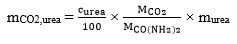 (25)
(25)
where:
mCO2,urea CO2 mass emission resulting from urea, g/test
curea urea concentration, per cent
murea total urea mass consumption, g/test
MCO(NH2)2 is the Molecular mass of urea: 60,056 g/mol
Then the total CO2 emission shall be calculated with equation 26:
 (26)
(26)
The brake specific CO2 emissions, eCO2 shall then be calculated according to section 3.3. of Annex 12.
11. Documentation requirements
11.1. Documentation for installing in a vehicle a type approved HDDF engine
The manufacturer of a dual-fuel engine type-approved as separate technical unit shall include in the installation documents of its engine system the appropriate requirements that will ensure that the vehicle, when used on the road or elsewhere as appropriate, will comply with the requirements of this annex. This documentation shall include but is not limited to:
(a) The detailed technical requirements, including the provisions ensuring the compatibility with the OBD system of the engine system;
(b) The verification procedure to be completed.
The existence and the adequacy of such installation requirements may be checked during the approval process of the engine system.
11.1.1. In the case when the vehicle manufacturer who applies for approval of the installation of the engine system on the vehicle is the same manufacturer who received the type-approval of the dual-fuel engine as a separate technical unit, the documentation specified in paragraph 11.2. is not required.
12. Appendices
Appendix 1 Types of HDDF engines and vehicles - illustration of the definitions and requirements
Appendix 2 Activation and deactivation mechanisms of the counter(s), warning system, operability restriction, service mode in case of dual fuel engines and vehicles- Description and illustrations
Appendix 3 HDDF dual-fuel indicator, warning system, operability restriction - Demonstration requirements
Appendix 4 Additional emission test procedure requirements for dual-fuel engines
Appendix 5 Additional PEMS emission test procedure requirements for dual-fuel engines
Appendix 6 Determination of molar component ratios and ugas values for dual-fuel engines
Annex 15 - Appendix 1 Types of HDDF engines and vehicles - illustration of the definitions and main requirements
| GERWHTC1 | Idle on diesel | Warm-up on diesel | Operation on diesel solely | Operation in absence of gas | Comments |
Type 1A | GERWHTC ≥ 90 % | NOT Allowed | Allowed only on service mode | Allowed only on service mode | Service mode | |
Type 1B | GERWHTC ≥ 90 % | Allowed only on Diesel mode | Allowed only on diesel mode | Allowed only on diesel & service modes | Diesel mode | |
Type 2A | 10 % < GERWHTC < 90 % | Allowed | Allowed only on service mode | Allowed only on service mode | Service mode | GERWHTC ≥ 90 % allowed |
Type 2B | 10 % < GERWHTC < 90 % | Allowed | Allowed only on diesel mode | Allowed only on diesel & service modes | Diesel mode | GERWHTC ≥ 90 % allowed |
Type 3A | NEITHER DEFINED NOR ALLOWED |
Type 3B | GERWHTC ≤ 10 % | Allowed | Allowed only on diesel mode | Allowed only on diesel & service modes | Diesel mode | |
1 This average Gas Energy Ratio GERWHTC is calculated over the hot part of the WHTC test-cycle |
| | | | | | | |
Annex 15 - Appendix 2 Activation and deactivation mechanisms of the counter(s), warning system, operability restriction, service mode in case of dual-fuel engines and vehicles - Description and illustrations
A.2.1. Description of the counter mechanism
A.2.1.1. General
A.2.1.1.1. To comply with the requirements of this annex, the system shall contain a counter to record the number of hours during which the engine has been operated while the system has detected a malfunctioning gas supply.
A.2.1.1.2. This counter shall be capable of counting up to 30 minutes operating time. The counter intervals shall be no longer than 3 minutes. When reaching its maximum value permitted by the system, it shall hold that value unless the conditions allowing the counter to be reset to zero are met.
A.2.1.2. Principle of the counter mechanism
A.2.1.2.1. The counters shall operate as follows:
A.2.1.2.1.1. If starting from zero, the counter shall begin counting as soon as a malfunctioning gas supply is detected according to paragraph 7.2 of this annex and the corresponding diagnostic trouble code (DTC) has the status confirmed and active.
A.2.1.2.1.2. The counter shall halt and hold its current value if a single monitoring event occurs and the malfunction that originally activated the counter is no longer detected or if the failure has been erased by a scan tool or a maintenance tool.
A.2.1.2.1.2.1. The counter shall also halt and hold its current value when the service mode becomes active.
A.2.1.2.1.3. Once frozen, the counter shall be reset to zero and restart counting if a malfunction relevant to that counter is detected and the service mode activated.
A.2.1.2.1.3.1. Once frozen, the counter shall also be reset to zero when the monitors relevant to that counter have run at least once to completion of their monitoring cycle without having detected a malfunction and no malfunction relevant to that counter has been detected during 36 engine operating hours since the counter was last held.
A.2.1.3. Illustration of the counter mechanism
Figures A2.1.1 to A2.1.3 give via three use-cases an illustration of the counter mechanism
Figure A2.1.1
Illustration of the gas supply counter mechanism (Type A HDDF) - use-case 1
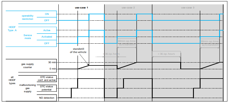
A malfunction of the gas supply is detected for the very first time.
The service mode is activated and the counter starts counting once the DTC gets the "confirmed and active" status (2nd detection).
The vehicle encounters a stand-still situation before reaching 30 minutes operating time after the service mode is activated.
The service mode becomes active and the vehicle speed is limited to 20 km/h (see paragraph 4.2.2.1. of this annex).
The counter freezes at its present value.
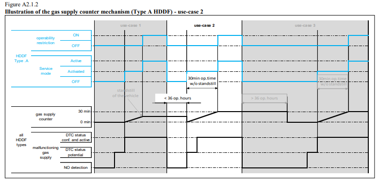
A malfunction of the gas supply is detected while the gas supply malfunction counter is not at zero (in this use-case it indicates the value it reached in use-case 1 when the vehicle became standstill).
The service mode is activated and the counter restarts counting from zero as soon as the DTC gets the "potential" status (1st detection: see paragraph 4.2.3.2.1. of this annex).
After 30 minutes of operation without a standstill situation, the service mode becomes active and the vehicle speed is limited to 20 km/h (see paragraph 4.2.2.1 of this annex).
The counter freezes at a value of 30 minutes operating time.

After 36 operating hours without detection of a malfunction of the gas supply, the counter is reset to zero (see paragraph A.2.1.2.3.2.1).
A malfunction of the gas supply is again detected while the gas supply malfunction counter is at zero (1st detection).
The service mode is activated and the counter starts counting once the DTC gets the "confirmed and active" status (2nd detection).
After 30 minutes of operation without a standstill situation, the service mode becomes active and the vehicle speed is limited to 20 km/h (see paragraph 4.2.2.1 of this annex).
The counter freezes at a value of 30 minutes operating time.
A.2.2. Illustration of the other activation and deactivation mechanisms
A.2.2.1. Empty gas tank
Figure A2.2 gives an illustration of the events occurring in the case of a HDDF vehicle when a gas tank becomes empty through one typical use-case.
Figure A2.2
Illustration of the events occurring in case of an empty gas tank (Types A and B HDDF)

In that use case:
(a) The warning system specified in paragraph 4.3.2. of becomes active when the level of gas reaches the critical level defined by the manufacturer;
(b) The service mode is activated (in the case of a Type A HDDF) or the engine switches to Diesel mode (in the case of a Type B HDDF).
In the case of a Type A HDDF, the service mode becomes active and the vehicle speed is limited to 20 km/h after the next time the vehicle is stationary or after 30 minutes operating time without standstill (see paragraph 4.2.2.1. of this annex).
The gas tank is refilled.
The vehicle operates again in dual-fuel mode as soon as the tank is refilled above the critical level.
A.2.2.2. Malfunctioning gas supply
Figure A2.3 gives via one typical use-case an illustration of the events occurring in the case of a malfunction of the gas supply system. This illustration should be understood as complementary to that given in section A.2.1 and dealing with the counter mechanism.
Figure A2.3
Illustration of the events occurring in case of a malfunctioning gas supply system (Types A and B HDDF)

In that use case:
(a) The failure of the gas supply system occurs for the very first time. The DTC gets the potential status (1st detection);
(b) The service mode is activated (in the case of a Type A HDDF) or the engine switches to Diesel mode (in the case of a Type B HDDF) as soon as the DTC gets the “confirmed and active” status (2nd detection).
In the case of a Type A HDDF, the service mode becomes active and the vehicle speed is limited to 20 km/h after the next time the vehicle is stationary or after 30 minutes operating time without standstill (see paragraph 4.2.2.1 of this annex).
The vehicle operates again in dual-fuel mode as soon as the failure is repaired.
A.2.2.3. Abnormality of the gas consumption
Figure A2.4 gives via one typical use-case an illustration of the events occurring in the case of an abnormality of the gas consumption.
Figure A2.4
Illustration of the events occurring in case of abnormality of gas consumption (Types A and B HDDF)

In that use case the service mode is activated (in the case of a Type A HDDF) or the engine switches to Diesel mode (in the case of a Type B HDDF) as soon as the DTC gets the "potential" status (1st detection).
In the case of a Type A HDDF, the service mode becomes active and the vehicle speed is limited to 20 km/h after the next time the vehicle is stationary or after 30 minutes operating time without standstill (see paragraph 4.2.2.1. of this annex).
The vehicle operates again in dual-fuel mode as soon as the abnormality is rectified.
Annex 15 - Appendix 3 HDDF dual-fuel indicator, warning system, operability restriction - Demonstration requirements
A.3.1. Dual-fuel indicators
A.3.1.1. Dual-fuel mode indicator
In the case where a dual-fuel engine is type approved as a separate technical unit, the ability of the engine system to command the activation of the dual-fuel mode indicator when operating in dual-fuel mode shall be demonstrated at type-approval.
In the case where a dual-fuel vehicle is type approved as regards to its emissions, the activation of the dual-fuel mode indicator when operating in dual-fuel mode shall be demonstrated at type-approval.
Note: Installation requirements related to the dual-fuel mode indicator of an approved dual-fuel engine are specified in paragraph 6.2. of this annex.
A.3.1.2. Diesel mode indicator
In the case where a dual-fuel engine of Type 1B, Type 2B, or Type 3B is type approved as a separate technical unit, the ability of the engine system to command the activation of the diesel mode indicator when operating in diesel mode shall be demonstrated at type-approval.
In the case where a dual-fuel vehicle of Type 1B, Type 2B, or Type 3B is type approved as regards to its emissions, the activation of the diesel mode indicator when operating in diesel mode shall be demonstrated at type-approval.
Note: Installation requirements related to the diesel mode indicator of an approved Type 1B, Type 2B, or Type 3B dual-fuel engine are specified in paragraph 6.2. of this annex.
A.3.1.3. Service mode indicator
In the case where a dual-fuel engine is type approved as a separate technical unit, the ability of the engine system to command the activation of the service mode indicator when operating in service mode shall be demonstrated at type-approval.
In the case where a dual-fuel vehicle is type approved with regard to its emissions, the activation of the service mode indicator when operating in service mode shall be demonstrated at type-approval.
Note: Installation requirements related to the service mode indicator of an approved dual-fuel engine are specified in paragraph 6.2. of this annex.
A.3.1.3.1. When so-equipped it is sufficient to perform the demonstration related to the service mode indicator by activating a service mode activation switch and to present the Type Approval Authority with evidence showing that the activation occurs when the service mode is commanded by the engine system itself (for example, through algorithms, simulations, result of in-house tests, etc. …).
A.3.2. Warning system
In the case where a dual-fuel engine is type approved as a separate technical unit, the ability of the engine system to command the activation of the warning system in the case that the amount of gas in the tank is below the warning level, shall be demonstrated at type-approval.
In the case where a dual-fuel vehicle is type-approved as regards to its emissions the activation of the warning system in the case that the amount of gas in the tank is below the warning level, shall be demonstrated at type-approval. For that purpose, at the request of the manufacturer and with the approval of the Type Approval Authority, the actual amount of gas may be simulated.
Note: Installation requirements related to the warning system of an approved dual-fuel engine are specified in paragraph 6.2. of this annex.
A.3.3. Operability restriction
In the case where a Type 1A or Type 2A dual-fuel engine is type approved as a separate technical unit, the ability of the engine system to command the activation of the operability restriction upon detection of an empty gaseous fuel tank, of a malfunctioning gas supply system, and of an abnormality of gas consumption in dual-fuel mode shall be demonstrated at type-approval.
In the case where a Type 1A or Type 2A dual-fuel vehicle is type approved as regards to its emissions, the activation of the operability restriction upon detection of an empty gaseous fuel tank, of a malfunctioning gas supply system, and of an abnormality of gas consumption in dual-fuel mode shall be demonstrated at type-approval.
Note: Installation requirements related to the operability restriction of an approved dual-fuel engine are specified in paragraph 6.2. of this annex.
A.3.3.1. The malfunctioning of the gas supply and the abnormality of gas consumption may be simulated at the request of the manufacturer and with the approval of the Type Approval Authority.
In the case where a Type 1A or Type 2A dual-fuel engine is type approved as a separate technical unit, the ability of the engine system to command the activation of the operability restriction upon detection of an empty gaseous fuel tank, of a malfunctioning gas supply system, and of an abnormality of gas consumption in dual-fuel shall be demonstrated at type-approval.
In the case where a Type 1A or Type 2A dual-fuel vehicle is type approved as regards to its emissions, the activation of the operability restriction upon detection of an empty gaseous fuel tank, of a malfunctioning gas supply system, and of an abnormality of gas consumption in dual-fuel mode shall be demonstrated at type-approval.
Note: Installation requirements related to the operability restriction of an approved dual-fuel engine are specified in paragraph 6.2. of this annex.
A.3.3.1. The malfunctioning of the gas supply and the abnormality of gas consumption may be simulated at the request of the manufacturer and with the approval of the Type Approval Authority.
A.3.3.2. It is sufficient to perform the demonstration in a typical use-case selected with the agreement of the Type Approval Authority and to present that authority with evidence showing that the operability restriction occurs in the other possible use-cases (for example, through algorithms, simulations, result of in-house tests, etc.
Annex 15 - Appendix 4 Additional emission test procedure requirements for dual-fuel engines
A.4.1. General
This appendix defines the additional requirements and exceptions to Annex 4 of this regulation to enable emission testing of dual-fuel engines independent whether these emissions are solely exhaust emissions or also crankcase emissions added to the exhaust emissions according to paragraph 6.10. of Annex 4.
Emission testing of a dual-fuel engine is complicated by the fact that the fuel used by the engine can vary between pure diesel fuel and a combination of mainly gaseous fuel with only a small amount of diesel fuel as an ignition source. The ratio between the fuels used by a dual-fuel engine can also change dynamically depending of the operating condition of the engine. As a result special precautions and restrictions are necessary to enable emission testing of these engines.
A.4.2. Test conditions (Annex 4, section 6.)
A.4.2.1. Laboratory test conditions (Annex 4, paragraph 6.1.)
The parameter fa for dual-fuel engines shall be determined with formula (a)(2) in paragraph 6.1. of Annex 4 to this Regulation.
A.4.3. Test procedures (Annex 4, section 7.)
A.4.3.1. Measurement procedures (Annex 4, paragraph 7.1.3.)
The recommended measurement procedure for dual-fuel engines is procedure (b) listed in paragraph 7.1.3. of Annex 4 (CVS system).
This measurement procedure ensures that the variation of the fuel composition during the test will only influence the hydrocarbon measurement results. This shall be compensated via one of the methods described in section 4.4.
Other measurement methods such as method (a) listed in paragraph 7.1.3. of Annex 4 (raw gaseous/partial flow measurement) can be used with some precautions regarding exhaust mass flow determination and calculation methods. Fixed values for fuel parameters and ugas-values shall be applied as described in Appendix 6.
A.4.4. Emission calculation (Annex 4, section 8.)
The emissions calculation on a molar basis, in accordance with Annex 7 of gtr No. 11 concerning the exhaust emission test protocol for Non-Road Mobile Machinery (NRMM), is not permitted.
A.4.4.1. Dry/wet correction (Annex 4, section 8.1.)
A.4.4.1.1. Raw exhaust gas (Annex 4, paragraph 8.1.1.)
Equations 15 and 17 in Annex 4, paragraph 8.1.1. shall be used to calculate the dry/wet correction.
The fuel specific parameters shall be determined according to sections A.6.2. and A.6.3. of Appendix 6.
A.4.4.1.2. Diluted exhaust gas (Annex 4, paragraph 8.1.2.)
Equations 19 and 20 in Annex 4 paragraph 8.1.2. shall be used to calculate the wet/dry correction.
The molar hydrogen ratio α of the combination of the two fuels shall be used for the dry/wet correction. This molar hydrogen ratio shall be calculated from the fuel consumption measurement values of both fuels according to section A.6.4. of Appendix 6.
A.4.4.2. NOx correction for humidity (Annex 4, section 8.2.)
The NOx humidity correction for compression ignition engines as specified in paragraph 8.2.1. of Annex 4 shall be used to determine the NOx humidity correction for dual-fuel engines.
 (A4.1)
where:
Ha is the intake air humidity, g water per kg dry air
A.4.4.3. Partial flow dilution (PFS) and raw gaseous measurement (Annex 4, section 8.4.)
A.4.4.3.1. Determination of exhaust gas mass flow (Annex 4, paragraph 8.4.1.)
The exhaust mass flow shall be determined according to the direct measurement method as described in section 8.4.1.3.
Alternatively the airflow and air to fuel ratio measurement method according to paragraph 8.4.1.6. (equations 30, 31 and 32) may be used only if α, γ, δ and ε values are determined according to sections A.6.2. and A.6.3. of Appendix 6. The use of a zirconia-type sensor to determine the air fuel ratio is not allowed.
A.4.4.3.2. Determination of the gaseous components (Annex 4, section 8.4.2.)
The calculations shall be performed according to Annex 4, section 8. but the ugas-values and molar ratios as described in section A.6.2. and A.6.3. of Appendix 6 shall be used.
A.4.4.3.3. Particulate determination (Annex 4, section 8.4.3.)
For the determination of particulate emissions with the partial dilution measurement method the calculation shall be performed according to Annex 4, paragraph 8.4.3.2.
For controlling the dilution ratio one of the following two methods may be used:
- The direct mass flow measurement as described in paragraph 8.4.1.3.
- The airflow and air to fuel ratio measurement method according to paragraph 8.4.1.6. (equations 30, 31 and 32) may only be used when this is combined with the look ahead method described in paragraph 8.4.1.2. and if α, γ, δ and ε values are determined according to sections A.6.2. and A.6.3. of Appendix 6.
The quality check according to paragraph 9.4.6.1. shall be performed for each measurement.
A.4.4.3.4. Additional requirements regarding the exhaust gas mass flow meter
The flow meter referred to in sections A.4.4.3.1. and A.4.4.3.3. shall not be sensitive to the changes in exhaust gas composition and density. The small errors of e.g. pitot tube or orifice-type of measurement (equivalent with the square root of the exhaust density) may be neglected.
A.4.4.4. Full flow dilution measurement (CVS) (Annex 4, section 8.5.)
The possible variation of the fuel composition will only influence the hydrocarbons measurement results calculation. For all other components the appropriate equations from section 8.5.2. of Annex 4 shall be used.
The exact equations shall be applied for the calculation of the hydrocarbon emissions using the molar component ratios determined from the fuel consumption measurements of both fuels according to section A.6.4. of Appendix 6.
A.4.4.4.1. Determination of the background corrected concentrations (Annex 4, paragraph 8.5.2.3.2.)
To determine the stoïchiometric factor, the molar hydrogen ratio α of the fuel shall be calculated as the average molar hydrogen ratio of the fuel mix during the test according to section A.6.4. of Appendix 6.
Alternatively the Fs value of the gaseous fuel may be used in equation 59 or 60 of Annex 4.
A.4.5. Equipment specification and verification (Annex 4, section 9.)
A.4.5.1. Oxygen interference check gases (Annex 4, paragraph 9.3.3.4.)
The oxygen concentrations required for dual-fuel engines are equal to those required for compression ignition engines listed in table 8 in paragraph 9.3.3.4. of Annex 4.
A.4.5.2. Oxygen interference check (Annex 4, paragraph 9.3.7.3.)
Instruments used to measure dual-fuel engines shall be checked using the same procedures as those used to measure compression ignition engines. The 21 per cent oxygen blend shall be used under item (b) in paragraph 9.3.7.3. of Annex 4.
A.4.5.3. Water quench check (Annex 4, paragraph 9.3.9.2.2.)
The water quench check in paragraph 9.3.9.2.2. of Annex 4 to this regulation applies to wet NOx concentration measurements only. For dual-fuel engines fuelled with natural gas this check should be performed with an assumed H/C ratio of 4 (Methane). In that case Hm = 2 x A. For dual-fuel engines fuelled with LPG this check should be performed with an assumed H/C ratio of 2.525. In that case Hm = 1.25 x A.
Annex 15 - Appendix 5 Additional PEMS emission test procedure requirements for dual-fuel engines
A.5.1. General
This appendix defines the additional requirements and exceptions to Annex 8 of this regulation to enable PEMS emission testing of dual-fuel engines.
Emission testing of a dual-fuel engine is complicated by the fact that the fuel used by the engine can vary between pure diesel fuel and a combination of mainly gaseous fuel with only a small amount of diesel fuel as an ignition source. The ratio between the fuels used by a dual-fuel engine can also change dynamically depending of the operating condition of the engine. As a result special precautions and restrictions are necessary to enable emission testing of these engines.
A.5.2. The following amendments to Appendix 1 of Annex 8 shall apply:
A.5.2.1. Note (2) of Table 1 in paragraph A.1.2.2. shall read:
(2) Only for engines fuelled with natural gas
A.5.2.2. Paragraph A.1.3.3. "Dry-Wet correction" shall read:
If the concentration is measured on a dry basis, it shall be converted to a wet basis according to paragraph 8.1. of Annex 4 and paragraph 4.1.1. of Appendix 4 to this annex.
A.5.2.3. Paragraph A.1.3.5. "Calculation of the instantaneous gaseous emissions" shall read:
The mass emissions shall be determined as described in paragraph 8.4.2.3. of Annex 4. The ugas values shall be determined according to sections A.6.2. and A.6.3. of appendix 6 of Annex 15.
Annex 15 - Appendix 6 Determination of molar component ratios and ugas values for dual-fuel engines
A.6.1. General
This appendix defines the determination of molar component ratios and ugas values for the dry-wet factor and emissions calculations for emission testing of dual-fuel engines.
A.6.2. Operation in dual-fuel mode
A.6.2.1. For Type 1A or 1B dual-fuel engines operating in dual-fuel mode the molar component ratios and the ugas values of the gaseous fuel shall be used.
A.6.2.2. For Type 2A or 2B dual-fuel engines operating in dual-fuel mode the molar component ratios and the ugas values from tables A6.1 and A6.2 shall be used.
Table A6.1
Molar component ratios for a mixture of 50% gaseous fuel and 50% diesel fuel (mass %)
Gaseous Fuel | α | γ | δ | ε |
CH4 | 2.8681 | 0 | 0 | 0.0040 |
GR | 2.7676 | 0 | 0 | 0.0040 |
G23 | 2.7986 | 0 | 0.0703 | 0.0043 |
G25 | 2.7377 | 0 | 0.1319 | 0.0045 |
Propane | 2.2633 | 0 | 0 | 0.0039 |
Butane | 2.1837 | 0 | 0 | 0.0038 |
LPG | 2.1957 | 0 | 0 | 0.0038 |
LPG Fuel A | 2.1740 | 0 | 0 | 0.0038 |
LPG Fuel B | 2.2402 | 0 | 0 | 0.0039 |
Table A6.2
Raw exhaust gas ugas values and component densities for a mixture of 50% gaseous fuel and 50% diesel fuel (mass %)
Gaseous Fuel
| e | | | Gas | | | |
NOx | CO | HC | CO2 | O2 | CH4 |
| | gas [kg/m3] | | | |
2.053 | 1.250 | a) | 1.9636 | 1.4277 | 0.716 |
| | ugasb) | | | |
CNG/LNGc) | 1.2786 | 0.001606 | 0.000978 | 0.000528d) | 0.001536 | 0.001117 | 0.000560 |
Propane | 1.2869 | 0.001596 | 0.000972 | 0.000510 | 0.001527 | 0.001110 | 0.000556 |
Butane | 1.2883 | 0.001594 | 0.000971 | 0.000503 | 0.001525 | 0.001109 | 0.000556 |
LPGe) | 1.2881 | 0.001594 | 0.000971 | 0.000506 | 0.001525 | 0.001109 | 0.000556 |
a) depending on fuel b) at = 2, dry air, 273 K, 101.3 kPa c) u accurate within 0.2 % for mass composition of: C = 58 - 76 %; H = 19 - 25 %; N = 0 - 14 % (CH4, G20, GR, G23 and G25) d) NMHC on the basis of CH2.93 (for total HC the ugas coefficient of CH4 shall be used) e) u accurate within 0.2 % for mass composition of: C3 = 27 - 90 %; C4 = 10 - 73 % (LPG Fuels A and B) |
A.6.2.3. For Type 3B dual-fuel engines operating in dual-fuel mode the molar component ratios and the ugas values of diesel fuel shall be used.
A.6.2.4. For the calculation of the hydrocarbon emissions of all types of dual-fuel engines operating in dual-fuel mode, the following shall apply:
- For the calculation of the THC emissions, the ugas value of the gaseous fuel shall be used.
- For the calculation of the NMHC emissions, the ugas value on the basis of CH2.93 shall be used.
- For the calculation of the CH4 emissions, the ugas value of CH4 shall be used.
A.6.3. Operation in diesel mode
For Type 1B, 2B or 3B dual-fuel engines operating in diesel mode, the molar component ratios and the ugas values of diesel fuel shall be used.
A.6.4. Determination of the molar component ratios when the fuel mix is known
A.6.4.1. Calculation of the fuel mixture components
 (A6.1)
 (A6.2)
 (A6.3)
 (A6.4)
 (A6.5)
where:
qmf1 fuel mass flow rate of fuel1, kg/s
qmf2 fuel mass flow rate of fuel2, kg/s
wALF hydrogen content of fuel, per cent mass
wBET carbon content of fuel, per cent mass
wGAM sulphur content of fuel, per cent mass
wDEL nitrogen content of fuel, per cent mass
wEPS oxygen content of fuel, per cent mass
A.6.4.2. Calculation of the molar ratios of H, C, S, N and O related to C for the fuel mixture (according to ISO8178-1, Annex A-A.2.2.2).
 (A6.6)
 (A6.7)
 (A6.8)
 (A6.9)
where:
wALF hydrogen content of fuel, per cent mass
wBET carbon content of fuel, per cent mass
wGAM sulphur content of fuel, per cent mass
wDEL nitrogen content of fuel, per cent mass
wEPS oxygen content of fuel, per cent mass
α molar hydrogen ratio (H/C)
γ molar sulphur ratio (S/C)
δ molar nitrogen ratio (N/C)
ε molar oxygen ratio (O/C)
referring to a fuel CHαONS
A.6.4.3. Calculation of the ugas values for a fuel mixture
The raw exhaust gas ugas values for a fuel mixture can be calculated with the exact equations in paragraph 8.4.2.4. of Annex 4 and the molar ratios calculated according to paragraph A.6.4.2.
For systems with constant mass flow, equation 57 in paragraph 8.5.2.3.1. of Annex 4 is needed to calculate the diluted exhaust gas ugas values.