Title: Australian Coat of Arms - Description: Australian Coat of Arms


Vehicle Standard (Australian Design Rule 99/00 – Lane Departure Warning Systems) 2023

I, CATHERINE KING, Minister for Infrastructure, Transport, Regional Development and Local Government, determine this national road vehicle standard under section 12 of the Road Vehicle Standards Act 2018.


Dated 14 September 2023


[SIGNED]

Catherine King

Minister for Infrastructure, Transport, Regional Development and Local Government


CONTENTS


1. LEGISLATIVE PROVISIONS....................................3

2. FUNCTION...................................................3

3. APPLICABILITY..............................................3

4. DEFINITIONS.................................................5

5. REQUIREMENTS..............................................5

6. EXEMPTIONS AND ALTERNATIVE PROCEDURES................5

7. ALTERNATIVE STANDARDS...................................6

APPENDIX A........................................................7

APPENDIX B.......................................................33

APPENDIX C.......................................................35


  1. LEGISLATIVE PROVISIONS
    1.                                     Name of Standard
      1.                               This standard is the Vehicle Standard (Australian Design Rule 99/00 – Lane Departure Warning Systems) 2023.
      2.                               This standard may also be cited as the Australian Design Rule 99/00 – Lane Departure Warning Systems, the Australian Design Rule 99/00, or ADR 99/00.
    2.                                     Commencement
      1.                               This standard commences on the day after it is registered.
  2. FUNCTION
    1.                                     The function of this vehicle standard is to specify requirements for Lane Departure Warning Systems fitted to medium and heavy goods vehicles, to warn a distracted or drowsy driver if the vehicle is unintentionally drifting out of its travel lane.
  3. APPLICABILITY
    1.                                     This vehicle standard applies from 1 October 2023 to sub-category NB2 and category NC vehicles, with an ‘Overall Width’ exceeding 2,500 mm.
    2.                                     Notwithstanding clause 3.1 above, a goods vehicle over 4.5 tonnes ‘Gross Vehicle Mass’ with an ‘Overall Width’ exceeding 2,500 mm is not required to comply with this vehicle standard if it:

(a)      has four or more ‘Axles’; or

(b)      is ‘designed for off-road use’, according to the applicable definition in Appendix B of this standard.

3.3.                                    This vehicle standard is optional for sub-category NB2 and category NC vehicles, with an ‘Overall Width’ not exceeding 2,500 mm.


3.4.                                    Applicability Table

Vehicle Category

ADR Category Code

UN Category Code*

Manufactured on or After

Acceptable Prior Rules

Moped 2 wheels

LA

L1

Not Applicable


Moped 3 wheels

LB

L2

Not Applicable


Motor cycle

LC

L3

Not Applicable


Motor cycle and sidecar

LD

L4

Not Applicable


Motor tricycle

LE

L5


   LEM


Not Applicable


   LEP


Not Applicable


   LEG


Not Applicable


Passenger car

MA

M1

Not Applicable


Forward-control passenger vehicle

MB

M1

Not Applicable


Off-road passenger vehicle

MC

M1

Not Applicable


Light omnibus

MD

M2


up to 3.5 tonnes ‘GVM’ and up to 12 seats

   MD1


Not Applicable


up to 3.5 tonnes ‘GVM’ and more than 12 seats

   MD2


Not Applicable


over 3.5 tonnes and up to 4.5 tonnes ‘GVM’

   MD3


Not Applicable


over 4.5 tonnes and up to 5 tonnes ‘GVM’

   MD4


Not Applicable


Heavy omnibus

ME

M3

Not Applicable


Light goods vehicle

NA

N1

Not Applicable


Medium goods vehicle

NB

N2


over 3.5 tonnes up to 4.5 tonnes ‘GVM’

   NB1


Not Applicable


over 4.5 tonnes up to 12 tonnes ‘GVM’

   NB2


See clauses
3.1 to 3.3

Nil

Heavy goods vehicle

NC

N3

See clauses
3.1 to 3.3

Nil

Very light trailer

TA

O1

Not Applicable


Light trailer

TB

O2

Not Applicable


Medium trailer

TC

O3

Not Applicable


Heavy trailer

TD

O4

Not Applicable


* The category code may also be in the format L1, L2, L3 etc.


4.                                          DEFINITIONS

4.1.                                    For vehicle categories, definitions and meanings used in this standard, refer to:

4.1.1.                              Vehicle Standard (Australian Design Rule – Definitions and Vehicle Categories) 2005;

4.1.2.                              Definitions in Appendix A of this standard; and

4.1.3.                              Definitions in Appendix B of this standard.

5.                                          REQUIREMENTS

5.1.                                    Vehicles must be equipped with a Lane Departure Warning System and meet the requirements of:

(a)      Appendix A, as varied by clause 6 (Exemptions and Alternative Procedures); or

(b)      the alternative standard under clause 7.1.

6.                                          EXEMPTIONS AND ALTERNATIVE PROCEDURES

6.1.                                    Compliance with the following parts, paragraphs and annexes of Appendix A is not required for the purposes of this standard:

Paragraph 3 Application for approval

Paragraph 4 Approval

Paragraph 7 Modification of vehicle type and extension of approval

Paragraph 8 Conformity of production

Paragraph 9 Penalties for non-conformity of production

Paragraph 10 Production definitively discontinued

Paragraph 11 Names and addresses of the Technical Services responsible for conducting approval tests and of Type Approval Authorities

Annexes

Annex 1  Communication

Annex 2  Arrangements of approval marks

6.2.                                    "Lane" shall mean one of the longitudinal strips into which a roadway is divided, as shown in Annex 3 of Appendix A, or as shown in Appendix C.

6.3.                                    The visible lane markings used in the lane departure warning tests of paragraph 6.5 of Appendix A must be:

(a)      those of one of the Contracting Parties as identified in Annex 3 to Appendix A, with the markings being in good condition and of a material conforming to the standard for visible lane markings of that Contracting Party; or

(b)      one of the Australian lane markings as identified in Appendix C, with the markings being in good condition and of a material conforming to the standard for visible lane markings in Australia.

6.3.1.                              The visible lane marking layout used for the testing must be recorded.

6.4.                                    Where the vehicle type can be equipped with different variants of the LDWS with regional specific adjustments; the requirements of this Regulation must at least be fulfilled for the Australian variants.

6.5.                                    Paragraphs 6.2.3.1, 6.2.3.2 and 6.2.3.3 of Appendix A shall not apply where the visible lane markings used in the lane departure warning tests of paragraph 6.5 of Appendix A are one of those for Australia, as permitted by clause 6.3(b) above, and identified in Appendix C below.

6.5.1.                              Where one of the Australian lane markings is used for the lane departure warning tests of paragraph 6.5 of Appendix A, compliance with all the other Australian lane markings identified in Appendix C below must also be demonstrated through either actual testing, or another means which is sufficiently valid and accurate to ensure the vehicle would comply if subjected to actual physical testing.

6.6.                                    Paragraph 5.2.1.1 of Appendix A may be met using either the lane markings as specified in paragraph 6.2.3. of Appendix A, or one of the lane markings for Australia identified in Appendix C.

6.7.                                    If there is a conflict between this clause 6 above and Appendix A below, this clause 6 takes precedence.

7.                                          ALTERNATIVE STANDARDS

7.1.                                    For vehicles equipped with a Lane Departure Warning System, the technical requirements of the United Nations Regulation No. 130 – UNIFORM PROVISIONS CONCERNING THE APPROVAL OF MOTOR VEHICLES WITH REGARD TO THE LANE DEPARTURE WARNING SYSTEM (LDWS), incorporating the original version of the regulation (00 series of amendments), including at least supplement 1 to the original version of the regulation.


APPENDIX A

Agreement

  Concerning the Adoption of Harmonized Technical United Nations Regulations for Wheeled Vehicles, Equipment and Parts which can be Fitted and/or be Used on Wheeled Vehicles and the Conditions for Reciprocal Recognition of Approvals Granted on the Basis of these United Nations Regulations[*]

(Revision 3, including the amendments which entered into force on 14 September 2017)

_________

Addendum: 129 – Regulation No. 130

  Incorporating by the Department of Infrastructure, Transport, Regional Development, Communications and the Arts, all valid text up to:


The original version of the Regulation – Date of entry into force: 9 July 2013

Supplement 1 to the original version of the Regulation – Date of entry into force: 8 October 2016

  Uniform provisions concerning the approval of motor vehicles with regard to the Lane Departure Warning System (LDWS)


UN Regulation No. 130

Uniform provisions concerning the approval of motor vehicles with regard to the Lane Departure Warning System (LDWS)

Contents

 Page

 0. Introduction.................................................... 9

 1. Scope........................................................ 10

 2. Definitions.................................................... 10

 3. Application for approval........................................... 10

 4. Approval..................................................... 11

 5. Specifications.................................................. 12

 6. Test procedure.................................................. 14

 7. Modification of vehicle type and extension of approval....................... 15

 8. Conformity of production........................................... 16

 9. Penalties for non-conformity of production............................... 16

 10.Production definitively discontinued.................................... 16

 11.Names and addresses of the Technical Services responsible for
conducting approval tests, and of Type Approval Authorities................... 17

Annexes

 1 Communication................................................. 18

 2 Arrangements of approval marks...................................... 19

 3 Visible lane marking identification..................................... 20


  Introduction

 The intention of this Regulation is to establish uniform provisions for Lane Departure Warning Systems (LDWS) fitted to motor vehicles of the categories M2, M3, N2 and N3[1] primarily used under highway conditions.

 These vehicle categories will benefit from the fitment of a LDWS, especially in the field of monotonous driving situations. The benefit of such system installation is to support a distracted or drowsy driver by warning if the vehicle is unintentionally leaving the lane.

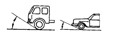
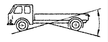
 While, in general, those vehicle categories will benefit from the fitment of a LDWS, there are subgroups where the benefit is rather uncertain because they are primarily used in other conditions than highway conditions (e.g. buses with standing passengers i.e. Classes I, II and A, off-road vehicles1, construction vehicles, special purpose vehicles, etc.). Regardless from the benefit, there are other subgroups where the installation of LDWS would be technically difficult (e.g. on vehicles equipped with split windshields, asymmetrical cabs, windshield of high thickness, front hood vehicles, vehicles with front mounted equipment, etc.).

 The system shall automatically detect unintentional drift of the vehicle out of its travel lane and warn the driver.

 The system shall provide a warning, so that an inattentive driver is made aware of a critical situation.

 The Regulation cannot include all the traffic conditions and infrastructure features in the type-approval process. Actual conditions and features in the real world should not result in false warnings to the extent that they encourage the driver to switch the system off.

1.  Scope

 This Regulation applies to the lane departure warning system of vehicles of categories M2, N2, M3 and N3.[2]

2.  Definitions

For the purposes of this Regulation:

2.1. "Approval of a vehicle type" means the full procedure whereby a Contracting Party to the Agreement certifies that a vehicle type meets the technical requirements of this Regulation;

2.2. "Vehicle type with regard to its Lane Departure Warning System" means a category of vehicles which do not differ in such essential respects as:

 (a) The manufacturer's trade name or mark;

 (b) Vehicle features which significantly influence the performances of the   Lane Departure Warning System;

 (c) The type and design of the Lane Departure Warning System;

2.3. "Lane Departure Warning System (LDWS)" means a system to warn the driver of an unintentional drift of the vehicle out of its travel lane;

2.4. "Lane" means one of the longitudinal strips into which a roadway is divided (as shown in Annex 3);

2.5. "Visible lane marking" means delineators intentionally placed on the borderline of the lane that are directly visible by the driver while driving (e.g. not covered by snow, etc.);

2.6. "Rate of departure" means the subject vehicle’s approach velocity at a right angle to the visible lane marking at the warning issue point;

2.7. "Common space" means an area on which two or more information functions (e.g. symbols) may be displayed, but not simultaneously.

3.  Application for approval

3.1. The application for approval of a vehicle type with regard to the LDWS shall be submitted by the vehicle manufacturer or by his authorized representative.

3.2. It shall be accompanied by the documents mentioned below in triplicate and include the following particular:

3.2.1. A description of the vehicle type with regard to the items mentioned in paragraph 5. below, together with dimensional drawings and the documentation as referred to in paragraphs 6.2.3.2. and 6.2.3.3. below. The numbers and/or symbols identifying the vehicle type shall be specified.

3.3. A vehicle representative of the vehicle type to be approved shall be submitted to the Technical Service conducting the approval tests.

4.  Approval

4.1. If the vehicle type submitted for approval pursuant to this Regulation meets the requirements of paragraph 5. below, approval of that vehicle type shall be granted.

4.2. An approval number shall be assigned to each vehicle type approved; its first two digits (00 for the Regulation in its initial form) shall indicate the series of amendments incorporating the most recent major technical amendments made to the Regulation at the time of issue of the approval. The same Contracting Party shall not assign the same number to the same vehicle type equipped with another type of Lane Departure Warning System, or to another vehicle type.

4.3. Notice of approval or of refusal or withdrawal of approval pursuant to this Regulation shall be communicated to the Parties to the Agreement applying this Regulation by means of a form conforming to the model in Annex 1 and photographs and/or plans supplied by the applicant being in a format not exceeding A4 (210 x 297 mm), or folded to that format, and on an appropriate scale.

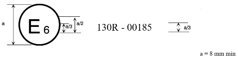
4.4. There shall be affixed, conspicuously and in a readily accessible place specified on the approval form, to every vehicle conforming to a vehicle type approved under this Regulation, an international approval mark conforming to the model described in Annex 2, consisting of:

4.4.1 A circle surrounding the letter "E" followed by the distinguishing number of the country which has granted approval;[3]

4.4.2. The number of this Regulation, followed by the letter "R", a dash and the approval number to the right of the circle prescribed in paragraph 4.4.1. above.

4.5. If the vehicle conforms to a vehicle type approved under one or more other Regulations annexed to the Agreement, in the country which has granted approval under this Regulation, the symbol prescribed in paragraph 4.4.1.  above need not be repeated; in such a case, the Regulation and approval numbers and the additional symbols shall be placed in vertical columns to the right of the symbol prescribed in paragraph 4.4.1. above.

4.6. The approval mark shall be clearly legible and be indelible.

4.7. The approval mark shall be placed close to or on the vehicle data plate.

5.  Specifications

5.1. General

5.1.1. Any vehicle fitted with a LDWS complying with the definition of paragraph 2.3. above shall meet the requirements contained in paragraphs 5.1 to 5.5. of this Regulation.

5.1.2. The effectiveness of LDWS shall not be adversely affected by magnetic or electrical fields. This shall be demonstrated by fulfilling the technical requirements and respecting the transitional provisions of Regulation No. 10 by applying:

 (a) The 03 series of amendments for vehicles without a coupling system   for charging the Rechargeable Energy Storage System (traction                             batteries);

 (b) The 04 series of amendments for vehicles with a coupling system for   charging the Rechargeable Energy Storage System (traction batteries).

5.2. Performance requirements

5.2.1. Whenever the system is active, as specified in paragraph 5.2.3. below, the LDWS shall warn the driver if the vehicle crosses over a visible lane marking for the lane in which it is running, on a road with a directional form that varies between straight and a curve having an inner lane marking with a minimum radius of 250 m, when there has been no purposeful demand to do so. Specifically:

5.2.1.1. It shall provide the driver with the warning specified in paragraph 5.4.1.  below when tested in accordance with the provisions of paragraph 6.5. below (departure warning test) and with lane markings as specified in paragraph 6.2.3. below.

5.2.1.2. The warning mentioned in paragraph 5.2.1. above may be suppressed when there is a driver action which indicates an intention to depart from the lane.

5.2.2. The system shall also provide the driver with the warning specified in paragraph 5.4.2. below when tested in accordance with the provisions of paragraph 6.6. below (failure detection test). The signal shall be constant.

5.2.3. The LDWS shall be active at least at vehicle speeds above 60 km/h, unless manually deactivated as per paragraph 5.3. below.

5.3. If a vehicle is equipped with a means to deactivate the LDWS function, the following conditions shall apply as appropriate:

5.3.1.  The LDWS function shall be automatically reinstated at the initiation of each new ignition "on" (run) cycle.

5.3.2.  A constant optical warning signal shall inform the driver that the LDWS function has been deactivated. The yellow warning signal specified in paragraph 5.4.2. below may be used for this purpose.

5.4. Warning indication

5.4.1. The lane departure warning referred to in paragraph 5.2.1. above shall be noticeable by the driver and be provided by:

 (a) At least two warning means out of optical, acoustic and haptic, or

 (b) One warning means out of haptic and acoustic, with spatial indication   about the direction of unintended drift of the vehicle.

5.4.1.1 Where an optical signal is used for the lane departure warning, it may use the failure warning signal as specified in paragraph 5.4.2. below in a flashing mode.

5.4.2. The failure warning referred to in paragraph 5.2.2. above shall be a yellow optical warning signal.

5.4.3. The LDWS optical warning signals shall be activated either when the ignition (start) switch is turned to the "on" (run) position or when the ignition (start) switch is in a position between the "on" (run) and "start" that is designated by the manufacturer as a check position (initial system (power-on)). This requirement does not apply to warning signals shown in a common space.

5.4.4. The optical warning signals shall be visible even by daylight; the satisfactory condition of the signals must be easily verifiable by the driver from the driver's seat.

5.4.5. When the driver is provided with an optical warning signal to indicate that the LDWS is temporarily not available, for example due to inclement weather conditions, the signal shall be constant. The failure warning signal specified in paragraph 5.4.2. above may be used for this purpose.

5.5. Provisions for the periodic technical inspection

5.5.1. At a periodic technical inspection it shall be possible to confirm the correct operational status of the LDWS by a visible observation of the failure warning signal status, following a "power-ON" (off–system OK, on–system fault present).

 In the case of the failure warning signal being in a common space, the common space must be observed to be functional prior to the failure warning signal status check.

5.5.2. At the time of type-approval, the means to protect against simple unauthorized modification of the operation of the failure warning signal chosen by the manufacturer shall be confidentially outlined.

 Alternatively, this protection requirement is fulfilled when a secondary means of checking the correct operational status of the LDWS is available.

6.  Test procedure

6.1.  The manufacturer shall provide a brief documentation package which gives access to the basic design of the system and, if applicable, the means by which it is linked to other vehicle systems. The function of the system shall be explained and the documentation shall describe how the operational status of the system is checked, whether there is an influence on other vehicle systems, and the method(s) used in establishing the situations which will result in a failure warning signal being displayed.

6.2. Test conditions

6.2.1. The test shall be performed on a flat, dry asphalt or concrete surface.

6.2.2. The ambient temperature shall be between 0° C and 45° C.

6.2.3. Visible lane markings

6.2.3.1. The visible lane markings used in the lane departure warning tests of paragraph 6.5. below shall be those of one of the Contracting Parties as identified in Annex 3 to this Regulation, with the markings being in good
condition and of a material conforming to the standard for visible lane markings of that Contracting Party. The visible lane marking layout used for the testing shall be recorded.

6.2.3.2. The vehicle manufacturer shall demonstrate, through the use of documentation, compliance with all the other lane markings identified in Annex 3 to this Regulation. Any such documentation shall be appended to the test report.

6.2.3.3. In the case the vehicle type may be equipped with different variants of the LDWS with regional specific adjustments; the manufacturer shall demonstrate through documentation that the requirements of this Regulation are fulfilled in all variants.

6.2.4. The test shall be performed under visibility conditions that allow safe driving at the required test speed.

6.3. Vehicle conditions

6.3.1. Test weight

 The vehicle may be tested at any condition of load, the distribution of the mass among the axles being that stated by the vehicle manufacturer without exceeding any of the maximum permissible mass for each axle. No alteration shall be made once the test procedure has begun. The vehicle manufacturer shall demonstrate through the use of documentation that the system works at all conditions of load.

6.3.2. The vehicle shall be tested at the tyre pressures recommended by the vehicle manufacturer.

6.3.3. In the case where the LDWS is equipped with a user-adjustable warning threshold, the test as specified in paragraph 6.5. below shall be performed with the warning threshold set at its maximum lane departure setting. No alteration shall be made once the test procedure has begun.

6.4.  Optical warning signal verification test

  With the vehicle stationary check that the optical warning signal(s) comply with the requirements of paragraph 5.4.3. above.

6.5. Lane departure warning test

6.5.1 Drive the vehicle at a speed of 65 km/h +/- 3 km/h into the centre of the test lane in a smooth manner so that the attitude of the vehicle is stable.

 Maintaining the prescribed speed, gently drift the vehicle, either to the left or the right, at a rate of departure of between 0.1 and 0.8 m/s so that the vehicle crosses the lane marking. Repeat the test at a different rate of departure within the range 0.1 and 0.8 m/s.

 Repeat the above tests drifting in the opposite direction.

6.5.2. The LDWS shall provide the lane departure warning indication mentioned in paragraph 5.4.1. above at the latest when the outside of the tyre of the vehicle’s front wheel closest to the lane markings crosses a line 0.3 m beyond the outside edge of the visible lane marking to which the vehicle is being drifted.

6.6. Failure detection test

6.6.1.  Simulate a LDWS failure, for example by disconnecting the power source to any LDWS component or disconnecting any electrical connection between LDWS components. The electrical connections for the failure warning signal of paragraph 5.4.2. above and the LDWS disable control of paragraph 5.3. above shall not be disconnected when simulating a LDWS failure.

6.6.2. The failure warning signal mentioned in paragraph 5.4.2.above  shall be activated and remain activated while the vehicle is being driven and be reactivated after a subsequent ignition "off" ignition "on" cycle as long as the simulated failure exists.

6.7. Deactivation Test

6.7.1  If the vehicle is equipped with means to deactivate the LDWS, turn the ignition (start) switch to the "on" (run) position and deactivate the LDWS. The warning signal mentioned in paragraph 5.3.2. above shall be activated. Turn the ignition (start) switch to the "off" position. Again, turn the ignition (start) switch to the "on" (run) position and verify that the previously activated warning signal is not reactivated, thereby indicating that the LDWS has been reinstated as specified in paragraph 5.3.1. above. If the ignition system is activated by means of a "key", the above requirement shall be fulfilled without removing the key.

7.  Modification of vehicle type and extension of approval

7.1. Every modification of the vehicle type as defined in paragraph 2.2. of this Regulation shall be notified to the Type Approval Authority which approved the vehicle type. The Type Approval Authority may then either:

7.1.1. Consider that the modifications made do not have an adverse effect on the conditions of the granting of the approval and grant an extension of approval;

7.1.2. Consider that the modifications made affect the conditions of the granting of the approval and require further tests or additional checks before granting an extension of approval.

7.2. Confirmation or refusal of approval, specifying the alterations, shall be communicated by the procedure specified in paragraph 4.3. above to the Contracting Parties to the Agreement applying this Regulation.

7.3. The Type Approval Authority shall inform the other Contracting Parties of the extension by means of the communication form which appears in Annex 1 to this Regulation. It shall assign a serial number to each extension, to be known as the extension number.

8.  Conformity of production

8.1. Procedures concerning conformity of production shall conform to the general provisions defined in Article 2 and Schedule 1 to the Agreement (E/ECE/TRANS/505/Rev.3) and meet the following requirements:

8.2. A vehicle approved pursuant to this Regulation shall be so manufactured as to conform to the type approved by meeting the requirements of paragraph 5. above;

8.3. The Type Approval Authority which has granted the approval may at any time verify the conformity of control methods applicable to each production unit. The normal frequency of such inspections shall be once every two years.

9.  Penalties for nonconformity of production

9.1. The approval granted in respect of a vehicle type pursuant to this Regulation may be withdrawn if the requirements laid down in paragraph 8. above are not complied with.

9.2. If a Contracting Party withdraws an approval it had previously granted, it shall forthwith so notify the other Contracting Parties applying this Regulation by sending them a communication form conforming to the model in Annex 1 to this Regulation.

10.  Production definitively discontinued

If the holder of the approval completely ceases to manufacture a type of vehicle approved in accordance with this Regulation, he shall so inform the Type Approval Authority which granted the approval, which in turn shall forthwith inform the other Contracting Parties to the Agreement applying this Regulation by means of a communication form conforming to the model in Annex 1 to this Regulation.

11.  Names and addresses of the Technical Services  responsible for conducting approval tests and of Type Approval Authorities

 The Contracting Parties to the Agreement applying this Regulation shall communicate to the United Nations Secretariat the names and addresses of the Technical Services responsible for conducting approval tests and of the Type Approval Authorities which grant approval and to which forms certifying approval or extension or refusal or withdrawal of approval are to be sent.


Annex 1

Communication

(Maximum format: A4 (210 x 297 mm))

Communication marking consisting of a circle with a capital E and the distinguishing number of the country which has granted, extended, refused or withdrawn an approval.

 Concerning:[4]  Approval granted

 Approval extended

 Approval refused

 Approval withdrawn

 Production definitively discontinued

of a type of vehicle with regard to the Lane Departure Warning System (LDWS) pursuant to UN Regulation No. 130

Approval No.:..................Extension No.: ......................

1. Trademark:................................................

2. Type and trade name(s):........................................

3. Name and address of manufacturer:................................

4. If applicable, name and address of manufacturer's representative: ............

5. Brief description of vehicle:.....................................

6. Date of submission of vehicle for approval: ...........................

7. Technical Service performing the approval tests: .......................

8. Date of report issued by that Service:...............................

9. Number of report issued by that Service:.............................

10. Approval with regard to the LDWS is granted/refused:2

11. Place:....................................................

12. Date:....................................................

13. Signature:.................................................

14. Annexed to this communication are the following documents, bearing the approval number indicated above:                           

15. Any remarks:...............................................

Annex 2

Arrangements of approval marks

(see paragraphs 4.4. to 4.4.2. of this Regulation)

Image showing the arrangement of an example approval mark for a vehicle type approved in Belgium with regard to a Lane Departure Warning System pursuant to the UN Regulation No. 130

The above approval mark affixed to a vehicle shows that the vehicle type concerned has been approved in Belgium (E 6) with regard to the LDWS pursuant to Regulation No. 130. The first two digits of the approval number indicate that the approval was granted in accordance with the requirements of Regulation No. 130 in its original form.


Annex 3

Visible lane marking identification

1. For the purpose of the approval test referred to in paragraphs 6.2.3. and 6.5. of this Regulation, the test lane width shall be greater than 3.5 m.

2. The visible lane markings identified in Table 1 below are assumed to be white, unless otherwise indicated in this annex.

3. Table of identified visible lane markings to be used for approval test in accordance with paragraphs 6.2.3. and 6.5. of this Regulation.

Table 1

Pattern

Country

Width

Left edge
lane marking

Centre line

Right edge
lane marking

Left edge
lane marking

Centre
line

Right edge
lane marking

Image showing how lane width is measured between the left edge, centre line and right edge lane markings for the purposes of this regulation.

Definition of lane width for the purpose of this Regulation


Image of first lane marking pattern for Canada, including a left edge lane marking and a centre line.

CANADA


Image of first lane marking pattern for Canada, including width dimensions for a left edge lane marking, a centre line, and a right edge lane marking.

Image of second lane marking pattern for Canada, including a left edge lane marking, a centre line and a right edge lane marking.

CANADA
Traffic Flowing in Opposite Direction


Image of second lane marking pattern for Canada, including width dimensions for a left edge lane marking, a centre line and a right edge lane marking.

Image of third lane marking pattern for Canada, including a left edge lane marking, a centre line and a right edge lane marking.

CANADA
Traffic flowing in same direction

Image of third lane marking pattern for Canada, including width dimensions for a left edge lane marking, a centre line and a right edge lane marking.

Image of fourth lane marking pattern for Canada, including a left edge lane marking, a centre line and a right edge lane marking.

CANADA
Traffic flowing in opposite directions with lane changing prohibited

Image of fourth lane marking pattern for Canada, including width dimensions for a left edge lane marking, a centre line and a right edge lane marking.

Image of fifth lane marking pattern for Canada, including a left edge lane marking, a centre line and a right edge lane marking.

CANADA
Traffic flowing in opposite directions with lane changing allowed only from one lane

Image of fifth lane marking pattern for Canada, including width dimensions for a left edge lane marking, a centre line and a right edge lane marking.

Image of sixth lane marking pattern for Canada, showing continuity lines in merging and diverging areas.

CANADA
Continuity lines in merging and diverging areas

Image of sixth lane marking pattern for Canada, showing width dimensions for continuity lines in merging and diverging areas.

Image of seventh lane marking pattern for Canada, showing guiding lines.

CANADA
Guiding Lines

Image of seventh lane marking pattern for Canada, showing width dimensions for guiding lines.

Image of lane marking pattern for Denmark, including a left edge lane marking, a centre line and a right edge lane marking.

DENMARK

Image of lane markings including width dimensions for Denmark, including a left edge lane marking, a centre line and a right edge lane marking.

Image of lane marking pattern for Finland, including a left edge lane marking, a centre line and a right edge lane marking.

FINLAND

Image of lane markings including width dimensions for Finland, including a left edge lane marking, a centre line and a right edge lane marking.

Image of a motorway lane marking pattern for France, including a left edge lane marking, a centre line and a right edge lane marking.

FRANCE

Motorway 1

Image of motorway lane markings including width dimensions for France, including a left edge lane marking, a centre line and a right edge lane marking.

Image of a highway lane marking pattern for France, including a left edge lane marking, a centre line and a right edge lane marking.

FRANCE

Highways (4 lanes or 2x2 lanes)

Image of highway lane markings including width dimensions for France, including a left edge lane marking, a centre line and a right edge lane marking.

Image of a lane marking pattern for other roads in France, including a left edge lane marking and a right edge lane marking.

FRANCE

(other roads)

Image of lane markings including width dimensions for other roads in France, including a left edge lane marking, a centre line and a right edge lane marking.

Image of secondary road lane markings  for Germany, including a left edge lane marking, a centre line and a right edge lane marking.

GERMANY Secondary

Image of secondary road lane markings for Germany, including width dimensions for a left edge lane marking, a centre line and a right edge lane marking.

Image of a motorway lane marking pattern for Germany, including a left edge lane marking, a centre line and a right edge lane marking.

GERMANY Motorway

Image of motorway lane markings for Germany, including width dimensions for a left edge lane marking, a centre line and a right edge lane marking.

Image of lane marking pattern for Greece, including a left edge lane marking, a centre line and a right edge lane marking.

GREECE

Image of lane markings including width dimensions for Greece, including a left edge lane marking, a centre line and a right edge lane marking.


Image of local and secondary road lane marking pattern for Italy, including a left edge lane marking, a centre line and a right edge lane marking.

ITALY

Secondary and Local

Image of secondary and local road lane markings including width dimensions for Italy, including a left edge lane marking, a centre line and a right edge lane marking.

Image of motorway lane marking pattern for Italy, including a left edge lane marking, a centre line and a right edge lane marking.

ITALY

Motorway


Image of motorway lane markings including width dimensions for Italy, including a left edge lane marking, a centre line and a right edge lane marking.

Image of main road lane marking pattern for Italy, including a left edge lane marking, a centre line and a right edge lane marking.

ITALY

Main

Image of main road lane markings including width dimensions for Italy, including a left edge lane marking, a centre line and a right edge lane marking.


Image of lane marking pattern for Ireland, including a left edge lane marking, a centre line and a right edge lane marking.

IRELAND

Image of lane markings including width dimensions for Ireland, including a left edge lane marking, a centre line and a right edge lane marking.

Image of lane marking pattern for Japan, including a left edge lane marking, a centre line and a right edge lane marking.

JAPAN

Image of lane markings including width dimensions for Japan, including a left edge lane marking, a centre line and a right edge lane marking.

Image of lane marking pattern for the Netherlands, including a left edge lane marking, a centre line and a right edge lane marking.

THE

NETHERLANDS

Image of lane markings including width dimensions for the Netherlands, including a left edge lane marking, a centre line and a right edge lane marking.

Image of lane marking pattern for Norway, including a left edge lane marking, a centre line and a right edge lane marking.

NORWAY

Image of lane markings including width dimensions for Norway, including a left edge lane marking, a centre line and a right edge lane marking.

Image of lane marking pattern for Portugal, including a left edge lane marking, a centre line and a right edge lane marking.

PORTUGAL

Image of lane markings including width dimensions for Portugal, including a left edge lane marking, a centre line and a right edge lane marking.

Image of first lane marking pattern for Russia, including a left edge lane marking, a centre line and a right edge lane marking.

RUSSIAN FEDERATION

More than one line in each direction

(Basic variant)


Image of first lane marking pattern for Russia, including width dimensions for a left edge lane marking, a centre line and a right edge lane marking.

Image of second lane marking pattern for Russia, including a left edge lane marking, a centre line and a right edge lane marking.

RUSSIAN FEDERATION

More than one line in each direction

(Variant 1 with a lane for reversing traffic)

Image of second lane marking pattern for Russia, including width dimensions for a left edge lane marking, a centre line and a right edge lane marking.

Image of third lane marking pattern for Russia, including a left edge lane marking, a centre line and a right edge lane marking.

RUSSIAN FEDERATION

More than one line in each direction

(Variant 2 with a lane for reversing traffic)

Image of third lane marking pattern for Russia, including width dimensions for a left edge lane marking, a centre line and a right edge lane marking.

Image of fourth lane marking pattern for Russia, including a left edge lane marking, and a right edge lane marking.

RUSSIAN FEDERATION

One line in each direction

(Variant 1)

Image of fourth lane marking pattern for Russia, including width dimensions for a left edge lane marking, and a right edge lane marking.

Image of fifth lane marking pattern for Russia, including a left edge lane marking, and a right edge lane marking.

RUSSIAN FEDERATION

One line in each direction

(Variant 2)

Image of fifth lane marking pattern for Russia, including width dimensions for a left edge lane marking, and a right edge lane marking.

Image of lane marking pattern for Spain, including a left edge lane marking, a centre line and a right edge lane marking.

SPAIN

Image of lane markings including width dimensions for Spain, including a left edge lane marking, a centre line and a right edge lane marking.

Image of lane marking pattern for Sweden, including a left edge lane marking, a centre line and a right edge lane marking.

SWEDEN

Image of lane markings including width dimensions for Sweden, including a left edge lane marking, a centre line and a right edge lane marking.

Image of lane marking pattern for Switzerland, including a left edge lane marking, a centre line and a right edge lane marking.

SWITZERLAND

Image of lane markings including width dimensions for Switzerland, including a left edge lane marking, a centre line and a right edge lane marking.

Image of motorway lane marking pattern for the United Kingdom, including a left edge lane marking, a centre line and a right edge lane marking.

UNITED KINGDOM

Motorway 1

Image of motorway lane markings including width dimensions for the United Kingdom, including a left edge lane marking, a centre line and a right edge lane marking.

Image of dual carriageway marking pattern for the United Kingdom, including a left edge lane marking, a centre line and a right edge lane marking.

UNITED KINGDOM

Dual Carriageway

Image of dual carriageway lane markings including width dimensions for the United Kingdom, including a left edge lane marking, a centre line and a right edge lane marking.

Image of single carriageway lane marking pattern for the United Kingdom, including a left edge lane marking, a centre line and a right edge lane marking.

UNITED KINGDOM

Single Carriageway (speed limit >40 mph)

Image of single carriageway lane markings including width dimensions for the United Kingdom, including a left edge lane marking, a centre line and a right edge lane marking.

1 Excepted certain zones (e.g.: slip road, lane for slow vehicles …)

* Note:

For the traffic speed limit up to 60 km/h:

a  = 1…3 m; b = 3…9 m; a:b = 1:3;

c  = 3…6 m; d = 1…2 m; c:d = 3:1;

e = 1 m; f = 2 m; e:f = 1:2

For the traffic speed limit above 60 km/h:

a  = 3…4 m; b = 9…12 m; a:b = 1:3;

c  = 6…9 m; d = 2…3 m; c:d = 3:1;

e = 2 m; f = 4 m; e:f = 1:2


APPENDIX B

Definitions used in this standard for medium and
heavy goods vehicles ‘designed for off-road use’

  1. Medium goods vehicles
    1.                            Category NB vehicles are considered to be ‘designed for off-road use’ if all their wheels are designed to be driven simultaneously, including vehicles where the drive to one ‘Axle’ can be disengaged, or if the following three criteria are satisfied:

(a)      At least one front ‘Axle’ and at least one rear ‘Axle’ are designed to be driven simultaneously, including vehicles where the drive to one ‘Axle’ can be disengaged; and

(b)      There is at least one differential locking mechanism or at least one mechanism having a similar effect; and

(c)      They can climb a 25 per cent gradient calculated for a solo vehicle.

2.                                 Heavy goods vehicles

2.1.                           Category NC vehicles are considered to be ‘designed for off-road use’ if all of the following criteria are satisfied:

(a)      All wheels are driven, except where applicable, when the drive to one ‘Axle’ is disengaged; and

(b)      There is at least one differential locking mechanism or at least one mechanism having a similar effect; and

(c)      They can climb a 25 per cent gradient calculated for a solo vehicle; and

(d)      At least four of the following six criteria are satisfied:

(i)        The ‘Approach Angle’ is at least 25°;

(ii)      The ‘Departure Angle’ is at least 25°;

(iii)   The ‘Breakover Angle’ is at least 25°;

(iv)    The ‘Ground Clearance’ under the front ‘Axle’ is at least 250 mm;

(v)      The ‘Ground Clearance’ between the ‘Axles’ is at least 300 mm;

(vi)    The ‘Ground Clearance’ under the rear ‘Axle’ is at least 250 mm.

3.                                 Load and checking conditions

3.1.                           The measurements referred to in clause 2.1 of this appendix are determined with the vehicle loaded to its ‘Gross Vehicle Mass’.

3.2.                           When measuring the ‘Approach Angle’ and the ‘Departure Angle’, no account is taken of underrun protective devices.

4.                                 Example Illustrations

4.1.                           Example illustrations of ‘Approach Angle’, ‘Departure Angle’ and ‘Breakover Angle’ are shown in Figures 1 to 3. In all cases, the lines shown in contact with tyres are tangent to the ‘Static Loaded Tyre Radius’ arc(s).

Figure 1, example illustrations of approach angle for a truck and a passenger car.

Figure 1 – Example illustrations of ‘Approach Angle’


Figure 2, example illustrations of departure angle for a truck and a passenger car.

Figure 2 – Example illustrations of ‘Departure Angle’


Figure 3, example illustration of breakover angle between the front and rear axles of a truck.

Figure 3 – Example illustration of ‘Breakover Angle’


APPENDIX C

Alternative lane markings

  1. Australian visible lane marking identification
    1.                            For the purpose of the test referred to in paragraphs 6.2.3 and 6.5 of Appendix A, the test lane width must be greater than 3.5 m.
      1.                     The lane width shall be measured as per the definition of lane width in Annex 3 to Appendix A of this rule above.
    2.                            The visible lane markings identified in Table 2 below are all white.

Table 2: Alternative table of Australian visible lane markings to be used for the tests in accordance with paragraphs 6.2.3. and 6.5. of Appendix A.

AUSTRALIA: Two-lane, two-way road, with one lane each way

Pattern

Width

Left edge
lane marking

Centre line

Right edge
lane marking

Left edge
lane marking

Centre line

Right edge
lane marking

Pattern image of left edge, centreline and right edge lane markings for two-lane, two-way road, with one lane each way.

Image with dimensions, of left edge, centreline and right edge lane markings for two-lane, two-way road, with one lane each way.

AUSTRALIA: Multi-lane road, with more than one lane each way, and a central dividing line

Pattern

Width

Left edge
lane marking

Centre line

Right edge
lane marking

Left edge
lane marking

Centre line

Right edge
lane marking

Pattern image of left edge, centreline and right edge lane markings for multi-lane road, with more than one lane each way, and a central dividing line.

Image with dimensions, of left edge, centreline and right edge lane markings for multi-lane road, with more than one lane each way, and a central dividing line.

AUSTRALIA: Two-lane, two-way road with lane changing allowed from one direction only

Pattern

Width

Left edge
lane marking

Centre line

Right edge
lane marking

Left edge
lane marking

Centre line

Right edge
lane marking

Pattern image of left edge, centreline and right edge lane markings for two-lane, two-way road, with lane changing allowed from one direction only.

Image with dimensions, of left edge, centreline and right edge lane markings for two-lane, two-way road, with lane changing allowed from one direction only.


AUSTRALIA: Two-lane, two-way road with lane changing not allowed

Pattern

Width

Left edge
lane marking

Centre line

Right edge
lane marking

Left edge
lane marking

Centre line

Right edge
lane marking

Pattern image of left edge, centreline and right edge lane markings for two-lane, two-way road, with lane changing not allowed.

Image with dimensions, of left edge, centreline and right edge lane markings for two-lane, two-way road, with lane changing not allowed.

AUSTRALIA: Two-lane, two-way road, with one lane each way and a single barrier line

Pattern

Width

Left edge
lane marking

Centre line

Right edge
lane marking

Left edge
lane marking

Centre line

Right edge
lane marking

Pattern image of left edge, centreline and right edge lane markings for two-lane, two-way road, with one lane each way and a single barrier line.

Image with dimensions, of left edge, centreline and right edge lane markings for two-lane, two-way road, with one lane each way and a single barrier line.


[*] Former titles of the Agreement:

 Agreement concerning the Adoption of Uniform Conditions of Approval and Reciprocal Recognition of Approval for Motor Vehicle Equipment and Parts, done at Geneva on 20 March 1958 (original version);

 Agreement concerning the Adoption of Uniform Technical Prescriptions for Wheeled Vehicles, Equipment and Parts which can be Fitted and/or be Used on Wheeled Vehicles and the Conditions for Reciprocal Recognition of Approvals Granted on the Basis of these Prescriptions, done at Geneva on 5 October 1995 (Revision 2).

 [1] As defined in the Consolidated Resolution on the Construction of Vehicles (R.E.3.), document ECE/TRANS/WP.29/78/Rev.6 - www.unece.org/trans/main/wp29/wp29wgs/wp29gen/wp29resolutions.html

 [2] As defined in section 2 of the Consolidated Resolution on the Construction of Vehicles (R.E.3) (document TRANS/WP.29/78/Rev.6) - www.unece.org/trans/main/wp29/wp29wgs/wp29gen/wp29resolutions.html


 [3] The distinguishing numbers of the Contracting Parties to the 1958 Agreement are reproduced in Annex 3 to the Consolidated Resolution on the Construction of Vehicles (R.E.3), document ECE/TRANS/WP.29/78/Rev.6 - www.unece.org/trans/main/wp29/wp29wgs/wp29gen/wp29resolutions.html


 [4]  Strike out what does not apply.